PW2UTX2KULTRA2 kW UHF Analog TV Transmitter
Pineapple Technology, Inc.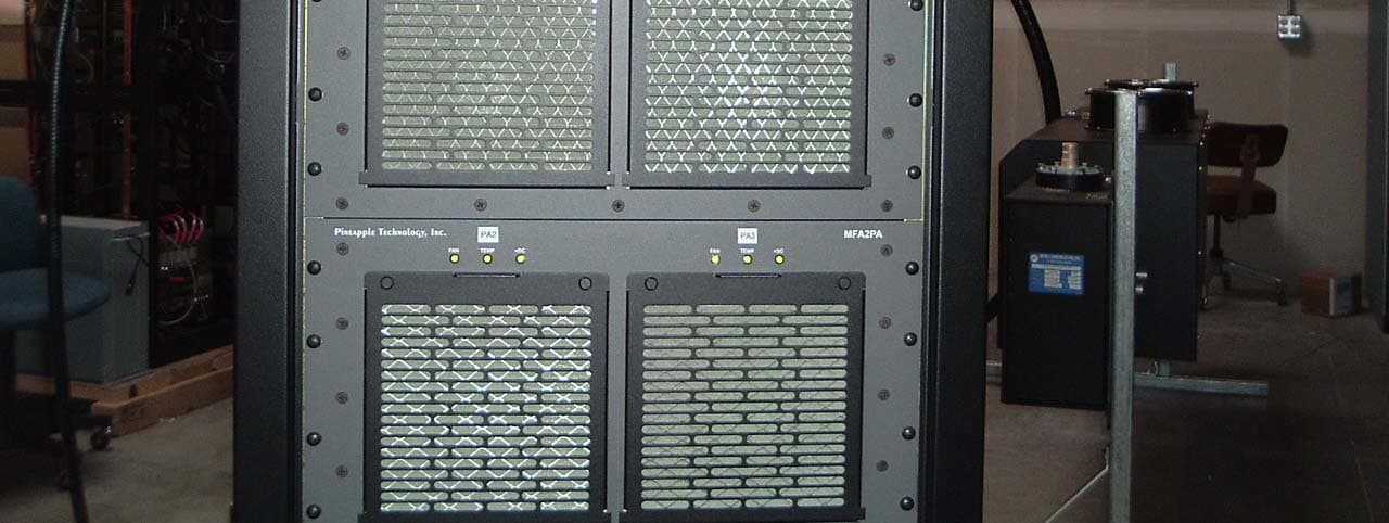
Click to zoom
Application Details
- Equipment Class
- TBC - Licensed Broadcast Station Transmitter
- Date of Grant
- May 18, 2006
- Application Purpose
- Original Equipment
- Date of Application
- Apr 17, 2006
- Equipment Note
- 2 kW UHF Analog TV Transmitter
- Frequency Range
- 470.00000000 - 806.00000000
- Company
- Pineapple Technology, Inc.
- Country
- United States
Documents & Files

Document Text
Text extracted from the exhibit documents filed with the FCC. Open a document above to read the original.
Attestation Statements
PINEAPPLE TECHNOLOGY INC. Quality Television Broadcast Equipment & Accessories 4231 Pacific Street Suite 27 Rocklin, CA 95677 916-652-1116 916-652-1161 FAX ROBERT R. ARTIGO President April 18, 2006 FCC Office of Equipment Authorization To Whom It May Concern: ATTESTATION STATEMENT I hereby certify the measurements and test results were made and recorded in accordance with accepted engineering practices and do constitute an accurate representation of the product performance of the documented UTX2KW ULTRA TV transmitter. Signed, President
Cover Letter(s)
1 April 19, 2006 FEDERAL COMMUNICATIONS COMMISSION OET Branch 445 12 ST. SW WASHINGTON, DC 20554 PINEAPPLE TECHNOLOGY INCORPORATED APPLICATION FOR UTX2KW ULTRA TV TRANSMITTER TYPE CERTIFICATION Pineapple Technology Inc. (PTI) has designed, built, tested and intends to market a Television transmitter with model UTX2KW ULTRA. Type certification is sought over the range of 2.0 kW to 500 W visual output power. This transmitter is a common amplification system with 5% aural power. The submission of the following exhibits is expected to demonstrate compliance with applicable Part 2, Part 73, and Part 74 rules and regulations. Sincerely, Greg Best Greg Best Consulting, Inc. 9223 N. Manning Ave. Kansas City, MO 64157 816-792-2913
Cover Letter(s)
May 1, 2006 Linda Elliott--FCC OET Equipment Authorization Branch Federal Communications Commission 445 12th Street, SW Washington, DC 20554 Dear Linda, This letter is to inform the OET Equipment Authorization Branch of the FCC of the desired transmitter model number for a TV transmitter model made by Pineapple Technologies Inc. (PTI). The correct model is the UTX2KULTRA and the corresponding FCCID is PW2UTX2KULTRA. The EA number for this application is EA823121. PTI appreciates your assistance in correcting this oversight made during the submission. If you have any questions you may feel free to contact me. Sincerely, Greg Best President Greg Best Consulting, Inc. 9223 N. Manning Ave. Kansas City, MO 64157 816-792-2913
Cover Letter(s)
May 1, 2006 Linda Elliott--FCC OET Equipment Authorization Branch Federal Communications Commission 445 12th Street, SW Washington, DC 20554 Dear Linda, This letter is to inform the OET Equipment Authorization Branch of the FCC of the desired transmitter model number for a TV transmitter model made by Pineapple Technologies Inc. (PTI). The correct model is the UTX2KULTRA and the corresponding FCCID is PW2UTX2KULTRA. The EA number for this application is EA823121. PTI appreciates your assistance in correcting this oversight made during the submission. If you have any questions you may feel free to contact me. Sincerely, Greg Best President Greg Best Consulting, Inc. 9223 N. Manning Ave. Kansas City, MO 64157 816-792-2913
External Photos
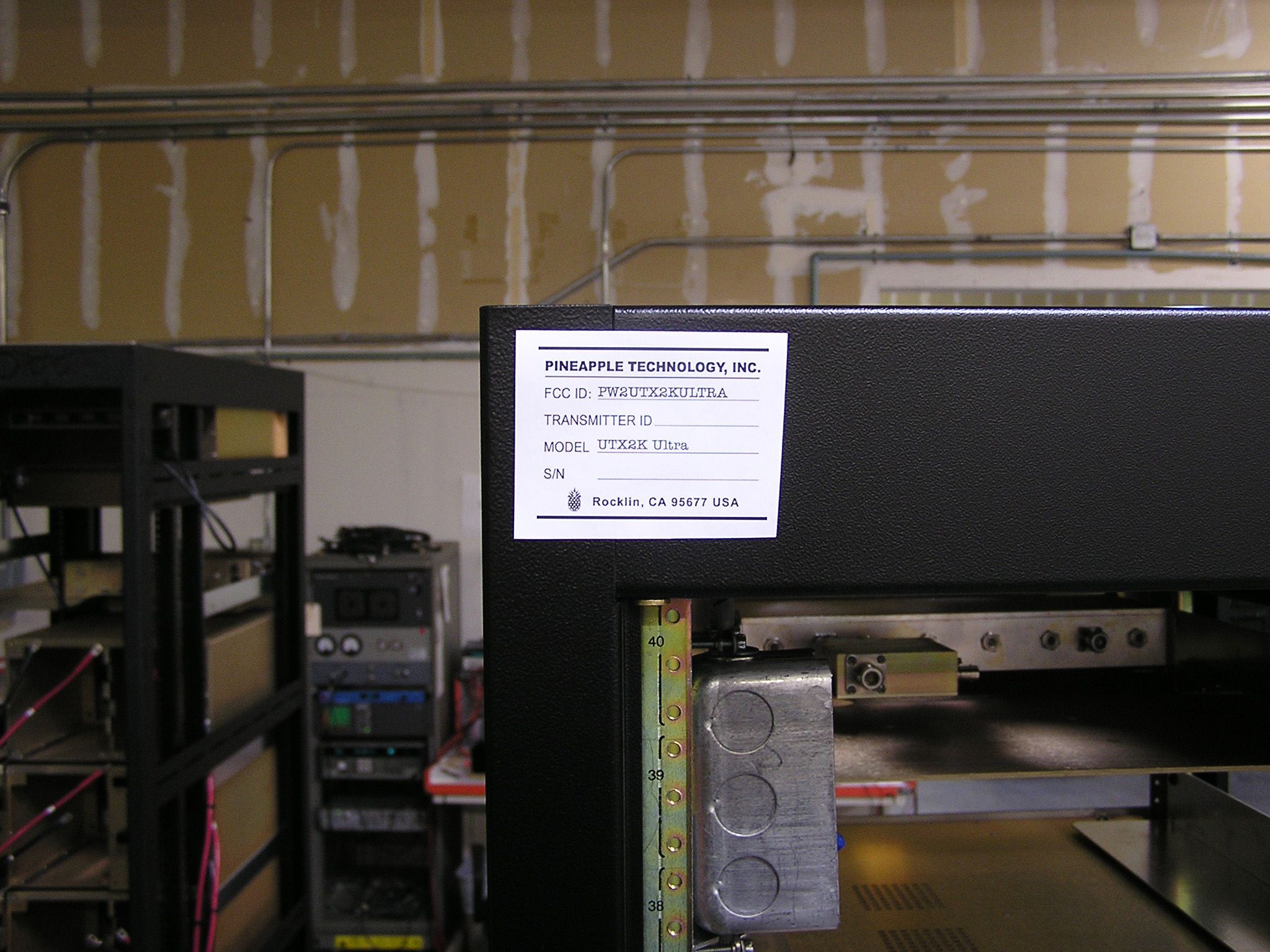
UTX2KW ULTRA EXTERNAL CONSTRUCTION PHOTOGRAPHS UTX2KW ULTRA FRONT UTX2KW ULTRA REAR UTX2KW ULTRA TOP FRONT UTX2KW ULTRA MIDDLE FRONT UTX2KW ULTRA BOTTOM FRONT UTX2KW ULTRA TOP REAR UTX2KW ULTRA MIDDLE REAR UTX2KW ULTRA BOTTOM REAR
Internal Photos
UTX2KW ULTRA INTERNAL CONSTRUCTION PHOTOGRAPHS REAR VIEW WITH DOOR OPEN UTX2KW ULTRA TOP REAR UTX2KW ULTRA MIDDLE REAR UTX2KW ULTRA BOTTOM REAR
Operational Description
THESE SPECIFICATIONS ARE SUBJECT TO CHANGE WITHOUT NOTICE. PINEAPPLE TECHNOLOGY, INC. UTX2K ULTRA Operating and Service Manual II – TRANSMITTER SPECIFICATIONS AUDIO PERFORMANCE Audio Response............................. Meets FCC Pre-emphasis curve Distortion...........................................< 1% THD FM Noise............................................. < 50 db or better AM Noise..........................................< 40 db or better AM Synchronous Noise......................... < 40 db typical GENERAL Operating Temperature.......................... -10 to +35 Degrees Celsius Ambient +14 to +95 Degrees Fahrenheit Ambient Altitude............................................ 5,000 ft without additional cooling Cooling Requirement............................ Unobstructed air flow to internal cooling system should be 2,000 CFM minimum RF Output Connectors...........................1 5/8” EIA Flange Weight.............................................450 lbs Dimensions Overall..............................23” x 77” x 32” (W x H x D) Page 4 Section III Transmitter Installation PINEAPPLE TECHNOLOGY, INC. UTX2K ULTRA Operating and Service Manual lll -- TRANSMITTER INSTALLATION lll -- TRANSMITTER INSTALLATION To ensure long and reliable trouble-free service from the UTX2K ULTRA transmitter the following steps for installation are recommended: 1. MECHANICAL INSTALLATION:The UTX2K ULTRA was designed to be installed in a building protected from the weather. The building should have a hard-surface floor such as concrete with a moisture barrier. This barrier could be pressure-treated wood sub flooring which could be anchored to the concrete and to the transmitter to make the installation earthquake resistant. Allow a minimum of three feet around the transmitter cabinet for service access. The top of the transmitter should be clear for three feet above to allow the air to exhaust from the transmitter. Air flow thru the transmitter is approximately 2,000 CFM. Provisions for air inlet and exhaust from the room must allow air flow with minimal obstruction. In the event that the room temperature exceeds 35º Celsius (95º F), cooling air must be provided so that the room temperature will no t exceed 35 degrees Celsius under worse case conditions. Notice: This equipment is HEAV Yand must be handled by professional movers with proper equipment. Any damage caused by the installers is not covered under warranty. Check to ensure that installing crews have proper insurance coverage. 2. GROUNDING: Transmitter grounding is VERY IMPORTANTand must be done correctly for safety and operational reasons. A typical installation may be done as follows: Use a heavy gauge wire such as #2 AWG stranded copper or solid copper buss one (1) inch wide by 1/8 inch thick for connections. The bonding between the transmitter and the ground rods mus t be good quality and protected from corrosion. The ground wires should run over the floor and be connected to the ground rods located outside the building. The wire should not go thru the concrete floor but over and around it. 3. AC WIRING: Wiring to the house electrical sub-panel will be routed to the AC terminal block mounted in the back of the rack. Connections to the AC Main should be made as follows: --- RED and BLACK are connected to the 220 VAC. --- WHITE WIRE is connected to NEUTRAL. ---GREEN WIRE is connected to SAFETY GROUND. NOTICE: All wiring of this type must be done by a QUALIFIED ELECTRICIAN and mus t conform to LOCAL and NATIONAL wiring CODES. Consult with your electrician to ensure that the proper breaker size is selected for the main circuit. 4. ANTENNA CONNECTION: The transmitter is equipped with 1 5/8" EIA flange connectors located at the top of the rack. Conditions vary from site to site so some engineering may be required to ensure that the antenna is receiving the correct amount of power to comply with FCC licenses and to ensure safety from lightning, etc. Page 5 Section IV Transmitter Turn-On PINEAPPLE TECHNOLOGY, INC. UTX2K ULTRA Operating and Service Manual lV -- TRANSMITTER TURN-ON PROCEDURE lV --- TRANSMITTER TURN-ON PROCEDURE Before applying AC Power to the transmitter for initial turn-on and check out, the installation should be approved by a qualified broadcast engineer. The turn-on procedure that follows is recommended by Pineapple Technology, Inc. engineering staff: 1.Check transmitter load or antenna for proper installation and connection to the transmitter. 2.Open the transmitter and inspect all cables and wires for loose connections or broken wires in the rack assembly. 3.Check for damage to the equipment mounted in the rack. 4.Check all AC breakers and on/off switched to ensure that they are all in the OFF position. 5.Turn-on Main AC breaker located in the house service sub-panel. 6. Turn-on the Main AC breaker located on the two (2) ACDIS2Power Distribution panel located on the front of Transmitter. A green light should come on indicating power is on. 7. Turn-on the AC Switch located on the front of the ADP500. The indicating lights should be on and ready for operation. 8. Turn-on the AUX Breaker located on the ACDIS2front panel. The PA fans and rack exhaust fans should come on. 9. Turn-on the AC Power breakers located on the front panel of the ACDIS2. Check the AC2009 power modules, three (3) each, to see if the green lights are lighted indicating normal operation. 10. Using the ADP500 and PAS3, check the idling currents on each PA to ensure that the currents are in the correct range. Typical range is 0.5 to 2.5 amps. See ADP500 Operating Section for details. NOTICE: The Modulator has been set at the factory so that the output power indication on the ADP500 will show 100% or 2 KW p-sync power level. It is important to read the instruction manual supplied with the modulator to locate key adjustment devices on the front panel. The output level adjustment will be necessary for the next step in the turn-on procedure. 11.Locate the output level…
Text truncated - open the document above for the full version.
Parts List/Tune Up Info
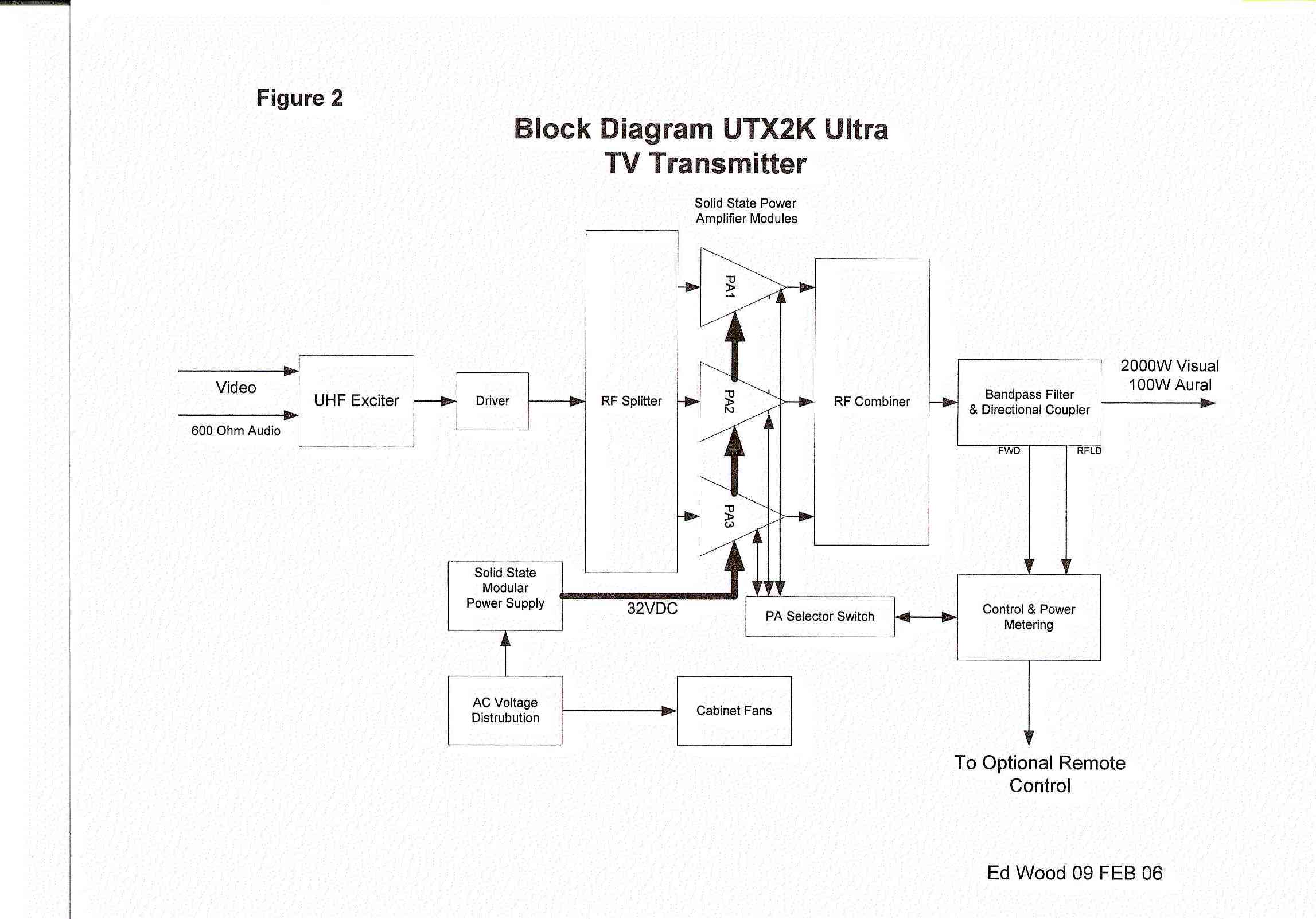
Section V Theory of Operation PINEAPPLE TECHNOLOGY, INC. UTX2K ULTRA Operating and Service Manual V -- THEORY OF OPERATION V --- THEORY OF OPERATION (Page 1 of 5) A. INTRODUCTION The UTX2K ULTRA transmitter was designed to meet or exceed all FCC applicable specifications for TV broadcast equipment. Special attention was given to the selection of sub-assemblies and components to achieve maximum reliability and minimum down time. The construction of the UTX2KW ULTRA is BASIC and MODULAR with most components field replaceable. Special emphasis was placed on "KEEPING IT SIMPLE" and returning to more traditional transmitter layouts and instrumentation. This transmitter was designed for Analog (NTSC) transmission with provisions and options available to convert to Digital Service at a later date if necessary. Refer to the UTX2K ULTRA block diagram in for an overview of the transmitter architecture. This will give the technician basic information needed to understand the operation of the transmitter and the function of each subassembly. SEE SECTION Vl.A FOR PARTS LIST AND BLOCK DIAGRAM. B. ACDIS2 AC & DC DISTRIBUTION The ACDIS2 is the primary AC power inlet module. The UTX2K ULTRA transmitter was designed to accept 208 to 240 VAC Single Phase using a four (4) wire connection. The four wires are: --- 2 wires for 208 -230 VAC Single Phase --- 1 wire for neutral connection --- 1 wire for safety ground connection CAUTION: Connection to the AC Primary source must be made using all four wires listed above. Follow the wiring instruction given in TRANSMITTER INSTALLATION Section lll.3. If not followed, severe damage to the transmitter and, or, electrical shock could result. The ACDIS2 performs the following functions: 1. Provides a primary AC power breaker point to shutdown the transmitter 2. Provides 208 VAC power to each of the 2 KW DC power supplies with individual breaker points for added safety. 3. Provides 110 VAC circuits for Modulator, ADP500, ABS (as necessary) and AUX Power where needed. 4. Analog metering is provided to monitor the Power Supply voltage and current being applied to the RF Amplifier states. 5. Power supply current sharing test points are provided for checking current sharing between power supply modules. SEE SECTION VI.B FOR SCHEMATIC AND PARTS LIS T C. AC2008 2KW POWER SUPPLY MODULE The UTX2K ULTRA transmitter is designed with over 6 KW of DC power. To achieve this level, the power supply in each transmitter rack is made up of three (3) TWRI6004 (PTI Part # AC2008) power modules mounted into one (1) main frame assembly (PTI Part # AC2009) which are capable of managing three (3) 2 KW modules each. Page 7 PINEAPPLE TECHNOLOGY, INC. UTX2K ULTRA Operating and Service Manual V -- THEORY OF OPERATION (CONTINUED) (Page 2 of 5) The power modules are "HOT PLUGGABLE" and can be removed or installed without turning off the transmitter. Each power supply module has OVER VOLTAGE, OVER CURRENT AND OVER TEMPERATURE protection as well as a fault signal in the event of a failure. REFER TO MANUFACTURER'S MANUAL FOR MODEL # TWRI6004 PROVIDED WITH THE UTX2K ULTRA. D. ADP500 AND PAS3 PERFORMANCE MONITO R The ADP500 AND PAS3 Performance Monitor provides the following functions: 1.Monitors FORWARD AND REFLECTED POWER to the antenna and presents it as a percentage of power rating. The transmitter comes set to 100% P-Sync power based on the ratings of the transmitter. 2.Monitors Aural Power as a percentage of P-Sync rating (5% typical). 3.Provides a HIGH ANTENNA VSWR MONITOR in the event of an antenna or coax failure where the reflected power exceeds 25% the transmitter will shut down. The front panel LED will change from green to red in case of a fault. 4.Provides current monitoring of all the pallets used in the three (3) PA1K power amplifier assemblies. The current levels can be read directly from the multi-meter on the front panel. Individual pallets are selectable on the ADP500 and the PA assemblies are selected using the PAS3. In normal operation, a PA FAULT is indicated by going from green to read. RED indicates that the current level is below 500 ma and a transistor may have failed. To read the actual current, select the appropriate PA Bank using the PAS3. The ADP500 will display status of each pallet in that PA. The multi-meter will read the actual current. 5.A PA INHIBIT switch is provided for failure diagonostic purposes. When activated, this switch allows the technician to monitor the bias currents for each pallet. These readings were recorded at the factory and are found on the Transmitter Test Report, DC Test Report Section. This is the best way to troubleshoot possible transistor problems. When in the PA INHIBIT mode, the RF PWR OFF LED will change from green to red indicating that the "SHUTDOWN LINE" is at TTL 0 state and the output power has been reduced to near zero. 6. An RF MONITOR port (BNC) is available to connect a spectrum analyzer for monitoring the output signal. 7.METER SELECTION SWITCHES The PAS3 is used to select the appropriate PA module (PA1K) for performance display on the ADP500. PA designations are PA1 starting from the top row left (there is no PA located in the top row right position) with PA3 and 4 located on the bottom row left to right. The rotary switch on the ADP500 is the detail selector for the multi-meter. The various positons are defined as follows: PA1 thru PA5....................................... ...Reads PA Pallet currents as selected Typical reading in INHIBIT MODE 1.5 to 2.5 A Typical reading SMPTE BARS 5-7 A for PA1 thru PA4 with normal picture Typical reading SMPTE BARS 2-3 A for PA5 with normal picture Page 8 PINEAPPLE TECHNOLOGY, INC. UTX2K ULTRA Operating and Service Manual V -- THEORY OF OPERATION (CONTINUED) (Page 3 of 5) 7.METER SELECTION SWITCHES (Continued) PA6................................................ No Connection PS VOLTS....................................... Reads DC voltage applied to PA stages Typical reading would be +29 to 3…
Text truncated - open the document above for the full version.
Schematics
Section V Theory of Operation PINEAPPLE TECHNOLOGY, INC. UTX2K ULTRA Operating and Service Manual V -- THEORY OF OPERATION V --- THEORY OF OPERATION (Page 1 of 5) A. INTRODUCTION The UTX2K ULTRA transmitter was designed to meet or exceed all FCC applicable specifications for TV broadcast equipment. Special attention was given to the selection of sub-assemblies and components to achieve maximum reliability and minimum down time. The construction of the UTX2KW ULTRA is BASIC and MODULAR with most components field replaceable. Special emphasis was placed on "KEEPING IT SIMPLE" and returning to more traditional transmitter layouts and instrumentation. This transmitter was designed for Analog (NTSC) transmission with provisions and options available to convert to Digital Service at a later date if necessary. Refer to the UTX2K ULTRA block diagram in for an overview of the transmitter architecture. This will give the technician basic information needed to understand the operation of the transmitter and the function of each subassembly. SEE SECTION Vl.A FOR PARTS LIST AND BLOCK DIAGRAM. B. ACDIS2 AC & DC DISTRIBUTION The ACDIS2 is the primary AC power inlet module. The UTX2K ULTRA transmitter was designed to accept 208 to 240 VAC Single Phase using a four (4) wire connection. The four wires are: --- 2 wires for 208 -230 VAC Single Phase --- 1 wire for neutral connection --- 1 wire for safety ground connection CAUTION: Connection to the AC Primary source must be made using all four wires listed above. Follow the wiring instruction given in TRANSMITTER INSTALLATION Section lll.3. If not followed, severe damage to the transmitter and, or, electrical shock could result. The ACDIS2 performs the following functions: 1. Provides a primary AC power breaker point to shutdown the transmitter 2. Provides 208 VAC power to each of the 2 KW DC power supplies with individual breaker points for added safety. 3. Provides 110 VAC circuits for Modulator, ADP500, ABS (as necessary) and AUX Power where needed. 4. Analog metering is provided to monitor the Power Supply voltage and current being applied to the RF Amplifier states. 5. Power supply current sharing test points are provided for checking current sharing between power supply modules. SEE SECTION VI.B FOR SCHEMATIC AND PARTS LIS T C. AC2008 2KW POWER SUPPLY MODULE The UTX2K ULTRA transmitter is designed with over 6 KW of DC power. To achieve this level, the power supply in each transmitter rack is made up of three (3) TWRI6004 (PTI Part # AC2008) power modules mounted into one (1) main frame assembly (PTI Part # AC2009) which are capable of managing three (3) 2 KW modules each. Page 7 PINEAPPLE TECHNOLOGY, INC. UTX2K ULTRA Operating and Service Manual V -- THEORY OF OPERATION (CONTINUED) (Page 2 of 5) The power modules are "HOT PLUGGABLE" and can be removed or installed without turning off the transmitter. Each power supply module has OVER VOLTAGE, OVER CURRENT AND OVER TEMPERATURE protection as well as a fault signal in the event of a failure. REFER TO MANUFACTURER'S MANUAL FOR MODEL # TWRI6004 PROVIDED WITH THE UTX2K ULTRA. D. ADP500 AND PAS3 PERFORMANCE MONITO R The ADP500 AND PAS3 Performance Monitor provides the following functions: 1.Monitors FORWARD AND REFLECTED POWER to the antenna and presents it as a percentage of power rating. The transmitter comes set to 100% P-Sync power based on the ratings of the transmitter. 2.Monitors Aural Power as a percentage of P-Sync rating (5% typical). 3.Provides a HIGH ANTENNA VSWR MONITOR in the event of an antenna or coax failure where the reflected power exceeds 25% the transmitter will shut down. The front panel LED will change from green to red in case of a fault. 4.Provides current monitoring of all the pallets used in the three (3) PA1K power amplifier assemblies. The current levels can be read directly from the multi-meter on the front panel. Individual pallets are selectable on the ADP500 and the PA assemblies are selected using the PAS3. In normal operation, a PA FAULT is indicated by going from green to read. RED indicates that the current level is below 500 ma and a transistor may have failed. To read the actual current, select the appropriate PA Bank using the PAS3. The ADP500 will display status of each pallet in that PA. The multi-meter will read the actual current. 5.A PA INHIBIT switch is provided for failure diagonostic purposes. When activated, this switch allows the technician to monitor the bias currents for each pallet. These readings were recorded at the factory and are found on the Transmitter Test Report, DC Test Report Section. This is the best way to troubleshoot possible transistor problems. When in the PA INHIBIT mode, the RF PWR OFF LED will change from green to red indicating that the "SHUTDOWN LINE" is at TTL 0 state and the output power has been reduced to near zero. 6. An RF MONITOR port (BNC) is available to connect a spectrum analyzer for monitoring the output signal. 7.METER SELECTION SWITCHES The PAS3 is used to select the appropriate PA module (PA1K) for performance display on the ADP500. PA designations are PA1 starting from the top row left (there is no PA located in the top row right position) with PA3 and 4 located on the bottom row left to right. The rotary switch on the ADP500 is the detail selector for the multi-meter. The various positons are defined as follows: PA1 thru PA5....................................... ...Reads PA Pallet currents as selected Typical reading in INHIBIT MODE 1.5 to 2.5 A Typical reading SMPTE BARS 5-7 A for PA1 thru PA4 with normal picture Typical reading SMPTE BARS 2-3 A for PA5 with normal picture Page 8 PINEAPPLE TECHNOLOGY, INC. UTX2K ULTRA Operating and Service Manual V -- THEORY OF OPERATION (CONTINUED) (Page 3 of 5) 7.METER SELECTION SWITCHES (Continued) PA6................................................ No Connection PS VOLTS....................................... Reads DC voltage applied to PA stages Typical reading would be +29 to 3…
Text truncated - open the document above for the full version.
Test Report
TEST REPORT PINEAPPLE TECHNOLOGY INC. UTX2KW ULTRA TV TRANSMITTER TECHNICAL REPORT INTRODUCTION The following information is provided to support the technical performance of the Pineapple Technology UTX2KW ULTRA TV Transmitter. The information is supplied for broadcast TV service according to applicable portions of FCC rules contained in Part 2, Part 73, and 74. 1. Power Output Measurements as indicated by FCC Rule Part 2.1046. 2. Frequency Measurements as identified by FCC Rule Part 2.1055. 3. Visual Frequency response measurements of the transmitter to be within the window specified by FCC Rule Part 74.750. 4. Occupied BW of aural signal specified by FCC Rule Part 2.1079. 5. Aural frequency response as identified by FCC Rule Part 73.687 6. Measurement of conducted harmonics and spurs +/- 3 MHz outside of channel as specified by FCC Rule Part 74.750 and Part 2 Rule 2.1051. 7. Measurement of cabinet radiation of spurs and harmonics as specified in FCC Rule 2.1053 and 2.1057. 8. Measurements of voltage and current to final amp stage as outlined in FCC Rule 2.1033. Measurements were conducted at a transmitter visual power output level of 2000 watts peak of sync and an aural power level of 100 watts. Some measurements were also carried out at 500 watts peak of sync to indicate that the performance was consistent over that power range. Measurements were taken on a unit with visual carrier frequency of 573.25 MHz and an aural carrier frequency of 577.75 MHz. The test equipment used for the measurements in this test report is listed at the back of this exhibit. All test equipment was calibrated prior to the use of the equipment by the supplier of the test equipment. RF POWER OUTPUT The equipment was configured as below shown in Figure 1. The loss through the RF output cable, directional coupler and attenuator was calibrated at the frequency of 573 MHz. The TSG-90 video generator was configured to produce a signal with 0 IRE video and sync. The audio generator and aural carrier were not energized. The visual portion of the transmitter was energized and the power was increased to the desired output power. The power was read on the HP-435 Power Meter and a reference level was established on the HP8590B Spectrum Analyzer. The TV demodulator and VM-700 were used to verify that sync compression was not causing distortion of the measurement. The aural carrier was energized and its output level was then raised to meet the precise 13 dB Visual/aural power ratio as observed on the spectrum analyzer. Pictures were also taken of demodulated video with 2 lines of a modulated stairstep (or reference white level) , and 2 fields of video to verify no signal distortions were present. POWER OUTPUT HP 435 Power Meter reading at high power= 10.8 mwatts Average Power = Meter reading + attenuator+ directional coupler loss + cable loss Average Power = 10.8 mwatts + 50.5 dB = 1211 watts Peak of sync power = 1.68 times average power = 1.68 x 1211 = 2035 watts 8590B Spectrum Analyzer TWO HORIZONTAL LINES AND TWO FIELDS SHOWING CORRECT MODULATION DEPTH FOR REFERENCE WHITE AND SYNC LEVELS AT 2.0 KW Power Output = 2.0 kwatts Power Output = 2.0 kwatts
Test Report
FREQUENCY STABILITY MEASUREMENTS Frequency stability versus temperature and line voltage was measured in a controlled environment. For these tests the exciter RF output was fed to a frequency counter that has better than a 1ppm accuracy. The test equipment configuration is shown below. Only the exciter was placed in the temperature chamber instead of the whole transmitter because of space limitations. This has no impact on the frequency stability of the transmitter since the stability is determined solely by the exciter frequency generation scheme. Frequency Stability versus line voltage variation Frequency Stability versus temperature The Variac was adjusted for nominal voltage and the frequency was recorded. Then the variac was adjusted to 85% and 115% of the nominal voltage and the frequency was recorded at each voltage level. For this test, the -10 kHz offset was used. The results are tabulated below. LINE VOLTAGE (Volts) Visual Frequency (MHz) Aural Frequency (MHz) 100 (85%) 507.239979 511.739882 121 (nominal) 507.239979 511.739882 140 (115%) 507.239979 511.739882 For the temperature stability measurements the exciter was placed inside a Tenney temperature chamber equipped with a MicroTenn II temperature controller. The exciter frequency was measured on the frequency counter. Measurements were first recorded at room temperature. The temperature in the chamber was changed to each of the points identified in the table below. The chamber followed a prescribed rate of change to reach each temperature and was then allowed to stabilize at the desired temperature for 10-15 minutes at which time frequency measurements were made. The temperature was cycled hot to 50°C and then gradually decreased until the entire range was covered. Temperature °C Time Visual Frequency (MHz) Aural Frequency (MHz) 25 1:30 507.250,000 511.749,913 50 2:50 507.249,793 511.750,038 40 3:10 507.249,781 511.749,818 30 3:20 507.249,955 511.749,877 20 3:30 507.249,885 511.749,770 10 3:45 507.249,577 511.794,407 0 4:00 507.249,434 511.749,343 -10 4:10 507.249,523 511.749,397 -20 4:20 507.249,567 511.750,816 -30 4:30 507.249,613 511.750,255 The recorded data indicates that the frequency stability requirements of FCC Rule 2.1055 were met. Exciter Frequency Counter Variac AC Input AC OutputRF Output Exciter Frequency Counter Temperature Chamber RF Output
Test Report
VISUAL TRANSMITTER FREQUENCY RESPONSE MEASUREMENTS The test equipment configuration of Figure 1 was used with the 1410 video generator supplying the video input waveform. For this test, the aural carrier was left energized. A variable frequency sine wave of 90 IRE Peak-to-Peak amplitude from 200 kHz to 6.0 MHz with pedestal set at 52.5 IRE input video waveform was used. The modulation output was increased until the maximum excursion reached reference white and 10 IRE as shown in the photo below. The frequency of the variable sine wave was varied between 200 kHz to 6.0 MHz in 500 kHz steps. The RF sideband output level was measured for the sidebands below and above the visual carrier. The frequency response was plotted. The plot is displayed on the next page to confirm that the radiated envelope meets the requirements as outlined in Part 74 Rule 750. FREQUENCY RESPONSE INPUT WAVEFORM The sweep amplitude of 90 IRE establishes a spectrum component at -14 dB reference to peak of sync output power. The frequency response measurements are tabulated below for upper and lower sideband values at transmitter output power of 2 kW and plotted on the next page to demonstrate compliance with the frequency response Rule 74.750. Index Frequency of modulating sine wave Lower Sideband level (dBc) Upper Sideband level (dBc) 0 Visual Carrier 0dBc 0dBc 1 200kHz -13 -14 2 500kHz -13 -14 3 1.0MHz -32 -14 4 1.5MHz -39 -14 5 2.0MHZ -39 -14 6 2.5MHz -40 -14 7 3.0MHz -44 -14 8 3.5MHz -48 -14 9 4.0MHz -55 -13 10 4.2MHz -62 -13 11 4.5MHz -65 -13 12 5.0MHz -60 -14 13 5.5MHz -64 -24 14 6.0MHz -71 -62 PLOT OF SPECTRUM AT POWER OUTPUT =2.0 kwatts Sideband Response -80 -70 -60 -50 -40 -30 -20 -10 0 10 -8-6-4-202468 Frequency from Carrier (MHz) Sideband Level (dBc)
Test Report
CONDUCTED SPURS AND HARMONICS CONDUCTED SPURIOUS OUTPUT The following photograph indicates the spurious performance (>+/- 3MHz) from the designated TV channel. As can be seen from the photos taken at a power level of 2.0kW, the spurious levels are >60 dB below the peak of sync of the visual carrier. The diamond in the top center of the screen indicates the true peak of sync of the visual carrier and the waveform indicates that the –4.5 MHz intermodulation (IM) product is 61.75 dB down from peak of sync. The +9 MHz IM product visible in the photo is at –72dB below the visual carrier. This photo indicates the desired 13dB aural to visual power level. The SPAN is 20MHz and the vertical scale is 10dB/div. POWER OUTPUT 2.0kW CONDUCTED HARMONIC OUTPUTS The following data indicates the harmonic performance of the UTX2KW ULTRA. The setup of Figure 1 was used to measure the harmonics. In this case the spectrum analyzer replaced the HP435 Power meter. Only the second and third harmonics were visible above the –75 dB noise floor of the spectrum analyzer. The following table displays the actual value of the harmonic that takes into account of the high power attenuators and cable used for the measurements. The value of <-75dB in the table indicates that the harmonic level was below the noise floor of the spectrum analyzer. Photographs of the spectrum containing the second and third harmonics are shown below. The pictures indicate that the harmonic levels are below 60 dB compared to the diamond at the top of the screen. HARMONIC LEVELS VS. FREQUENCY AT 2.0KW POWER OUTPUT Frequency of Harmon…
Text truncated - open the document above for the full version.
Contact Information
Applicant
Robert Artigo(President)
Technical Specifications
| # | Rule Parts | Frequency Range | Power Output | Emission | Tolerance |
|---|---|---|---|---|---|
| 2 | 73,74 | 470 MHz - 806 MHz | 100 W | 250KF3E | 1000 Hz |
Other Applications from Pineapple Technology, Inc.

PW2DTXPRO10U
Aug 31, 201110 W DTV TRANSMITTER
Equipment Class
TBC - Licensed Broadcast Station Transmitter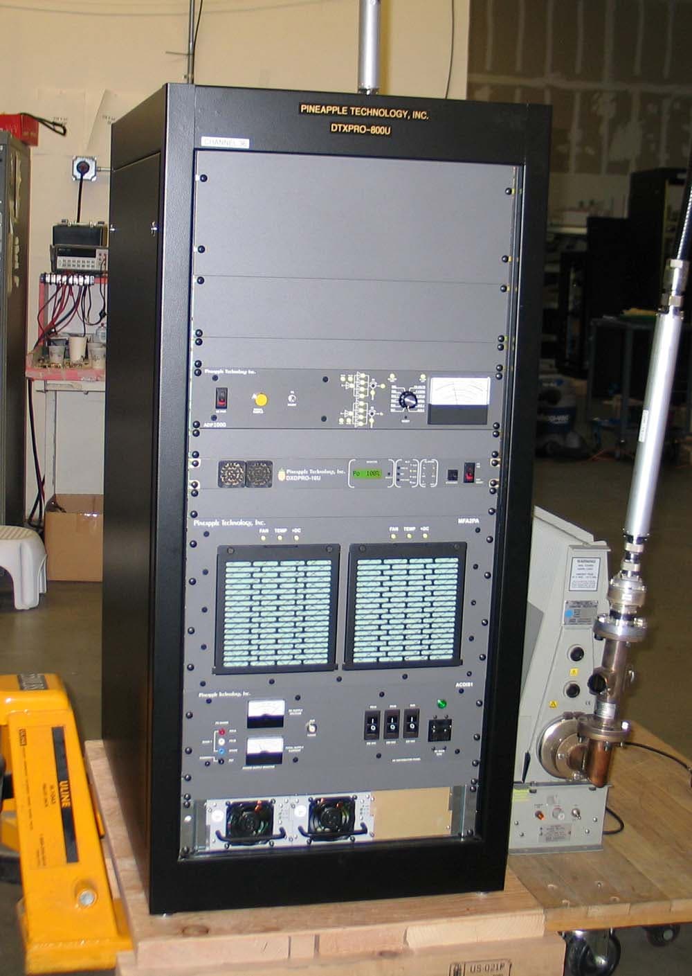
PW2DTXPRO800U
Mar 01, 2011800 W DTV TRANSMITTER
Equipment Class
TBC - Licensed Broadcast Station Transmitter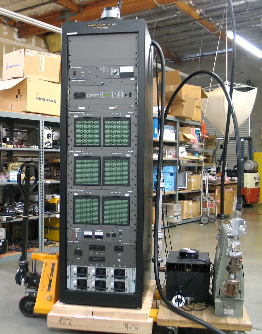
PW2DTXPRO2300U
Mar 01, 20112.3KW DTV TRANSMITTER
Equipment Class
TBC - Licensed Broadcast Station Transmitter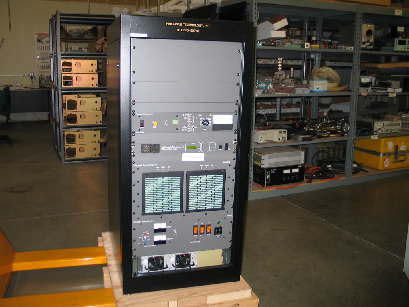
PW2DTXPRO800VH
Feb 27, 2011800 WATT DTV TRANSMITTER
Equipment Class
TBC - Licensed Broadcast Station Transmitter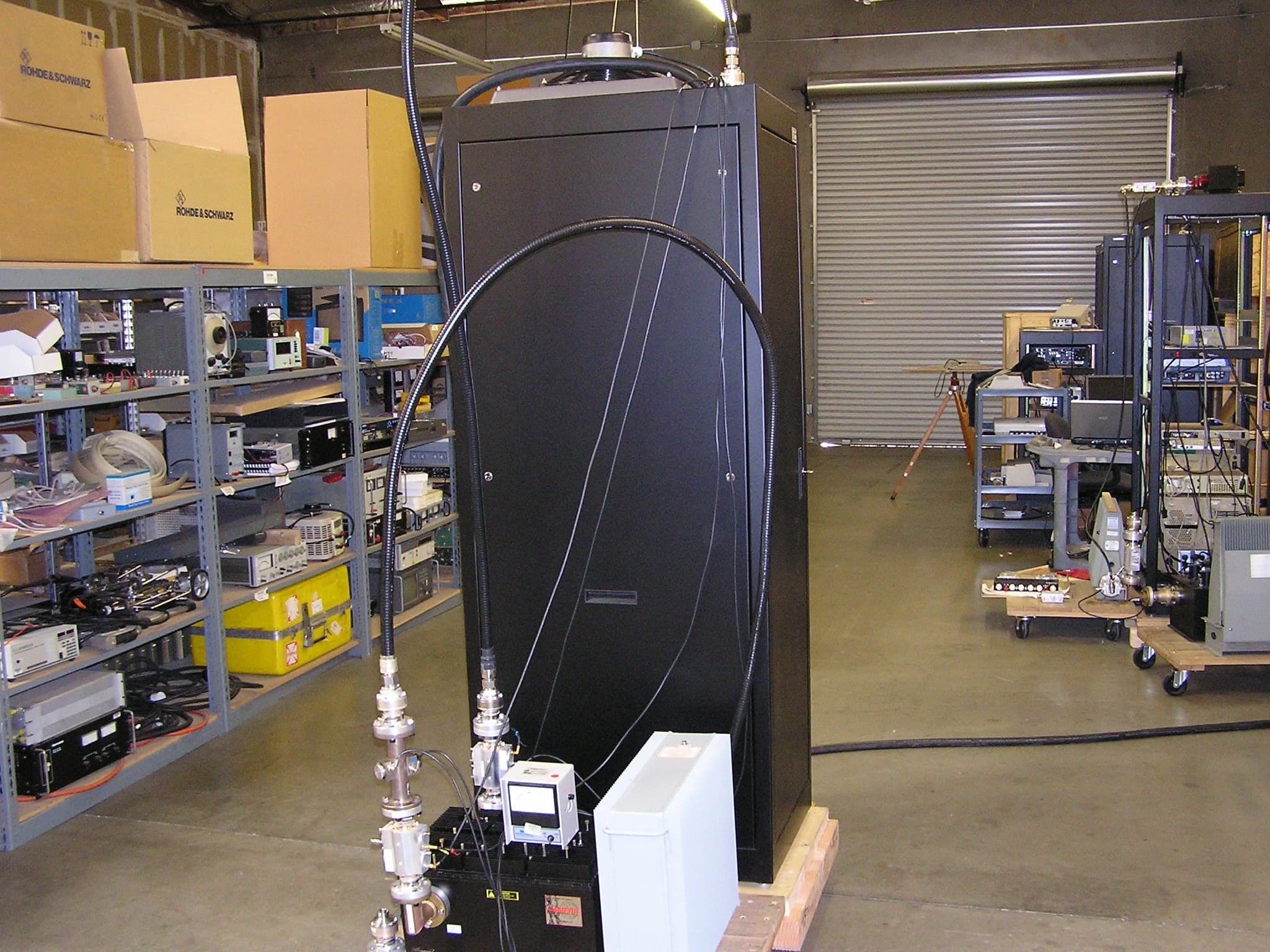
PW2DTXPRO1200U
Dec 12, 20101.2 KW DTV TRANSMITTER
Equipment Class
TBC - Licensed Broadcast Station Transmitter