PW9DTX2400LRT Transmitter module for use with Thermal Image Camera
E2V Technologies Ltd.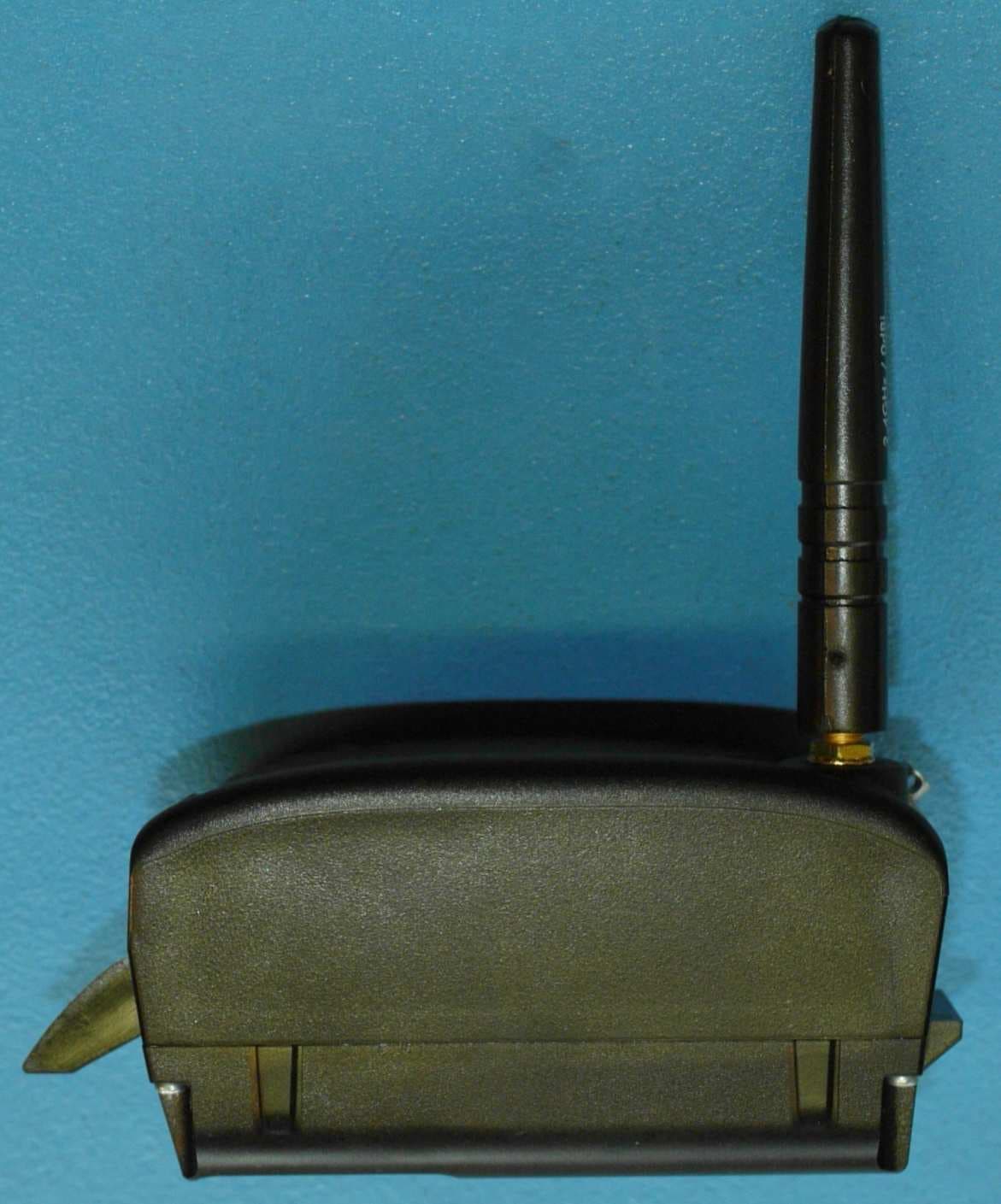
Click to zoom
Application Details
- Equipment Class
- TNB - Licensed Non-Broadcast Station Transmitter
- Date of Grant
- Aug 23, 2010
- Application Purpose
- Original Equipment
- Date of Application
- Aug 23, 2010
- Equipment Note
- LRT Transmitter module for use with Thermal Image Camera
- Frequency Range
- 2452.00000000 - 2482.00000000
- Company
- E2V Technologies Ltd.
- Country
- United Kingdom
Documents & Files
Document Text
Text extracted from the exhibit documents filed with the FCC. Open a document above to read the original.
Users Manual
USER GUIDE FOR ARGUS ® 4 VIDEO ACCESSORIES ©e2v technologies (uk) limited 2010 107553 09 Aug 2010 DAS762156AA (UK) Version 11, page 1 THERMAL IMAGING VIDEO ACCESSORIES SAFETY NOTES Before using this product, the customer shall read and understand all the instructions and warnings. e2v technologies does not accept responsibility for damage or injury resulting from failure to follow the instructions provided. WARNINGS: • The Argus ® 4 Video Accessories are despatched from e2v technologies in a safe condition. Any unauthorised modifications may compromise safety and invalidate the warranty. • The Argus ® 4 Video Accessories are not certified as intrinsically safe and therefore must not be operated in potentially flammable or explosive atmospheres. • All users must be trained in the correct operation, functionality and features of the Argus ® 4 before use. • The Argus ® 4 Video Accessories can only be serviced by authorised personnel. There are no end-user serviceable parts except those described in the maintenance section of this manual. • The Argus ® 4 LRT receiver contains a Lithium Ion battery. Do not allow the receiver to become heated above 80°C or subjected to extreme impact. • Neglecting the above may result in injury or death. LIMITATION OF USE: The Argus ® 4 Video Accessories are not certified for automotive use in immunity- related functions. It MUST NOT be used for the control of a vehicle, a vehicular safety system or in a way that may disturb the driver, data bus or statutory devices fitted to a vehicle. All matters arising, which relate to the safety of this product, should be reported immediately in writing, giving full details, to the Quality Engineering Manager at e2v technologies. ©e2v technologies (uk) limited 2010 107553 09 Aug 2010 DAS762156AA (UK) Version 11, page 2 RADIO COMPLIANCE Before using any transmitter accessory read the notes in sections 14, 15 & 16 appropriate to the product and country of use. It is the users’ responsibility to ensure that the frequency and power of operation are permitted in their locale. Failure to do so may result in illegal radio operation and prosecution. ENVIRONMENTAL e2v technologies declares that the Argus ® 4 Video Accessories comply with EC directive 2002/95/EC (the RoHS Directive) restricting the use of certain hazardous materials in electrical and electronic equipment. The Argus ® 4 Video Accessories are classified as Electronic and Electrical Equipment according to directive 2002/96/EC (the WEEE Directive) and should be segregated from domestic waste for disposal. Contact your local e2v sales office for disposal instructions. The P7030TX, P7030VC and P7030DTX contain a NiMH battery. Do not crush or dispose of in fire. The DRX and DRRS products contain a Li-Ion battery. Do not crush or dispose of in fire. China RoHS: This product does not contain toxic or hazardous substances or elements over the maximum permitted concentration values. Refer to the Argus ® 4 Thermal Image Camera customer information CD for more information. 本产品不含有毒、有害物质或其浓度在允许范围内。详细信息请查阅 随附的用户信息光盘 ©e2v technologies (uk) limited 2010 107553 09 Aug 2010 DAS762156AA (UK) Version 11, page 3 USER GUIDE FOR THE ARGUS ® 4 VIDEO ACCESSORIES This document explains to the user how to operate the Argus ® 4 External Video Accessories and applications for their use. Contents 1 General Overview 2 Transmitter and Battery Pack 3 Receiver 4 Receiver Kit 5 External Power and Video Adaptor 6 Analogue Output Battery Pack 7 Video Capture Battery Pack 8 LRT System 9 Installing the Ateme player 10 Applications and Advanced use 11 FAQ 12 Specifications 13 FCC Statement (All products applicable in USA and Canada) 14 Compliance and Legal Notices (P7030TX Transmitter) 15 Compliance and Legal Notices (DTX1400 LRT Transmitter) 16 Compliance and Legal Notices (DTX2400 LRT Transmitter) 17 Warranty ©e2v technologies (uk) limited 2010 107553 09 Aug 2010 DAS762156AA (UK) Version 11, page 4 SECTION 1 – General Overview The main applications for the Argus™4 video accessories are in remote command overview, training, evidence gathering and investigation. The user is offered a number of different solutions for viewing the camera images at a distance and for recording video from the camera. The user can choose between a fully configured system and the option to use the camera with existing equipment or to build a more complex system. The main departure from existing systems is that the camera has an output is in a computer-friendly format for the digital age allowing the use with standard networking equipment directly to a computer, providing files ready for use without the need for conversion. Additionally, analogue output is present on many camera variants allowing use with existing standard video equipment through the analogue accessories. The LRT accessories offer a very high performance video link that is also secure and can be interfaced with systems in use in command vehicles for other video cameras WiFi system P7030TX, P7030RRS and P7030RKT Sections 2,3 & 4 From page 3 Wired Systems P7030EPVA, P7030AVBP Sections 5 & 6 From page 14 Recorder P7030VC Section 7 From page 20 LRT System DTX1400 / DRX1400 / DRRS1400 DTX2400 / DRX2400 / DRRS2400 Section 8 From page 23 ©e2v technologies (uk) limited 2010 107553 09 Aug 2010 DAS762156AA (UK) Version 11, page 5 SECTION 2 - Argus ® 4 Transmitter and Battery Pack P7030TX This accessory allows an Argus ® 4 camera to transmit video over Wi-Fi to a suitable receiver and to be viewed on a computer connected to it. This is incorporated in a battery pack that provides power for both transmitter and camera. The Transmitter and battery pack consists of the following items: Transmitter and Battery Pack DAS761760AA Software CD DAS762581AA User Guide (this booklet) DAS762156AA Connection to the camera is by replacing the standard battery with the unit supplied. There are no user serviceable parts inside. INSTRUCTIONS FOR USE The transmitter battery pack contains a st…
Text truncated - open the document above for the full version.
Cover Letter(s)
BABT (TCB) Forsyth House Churchfield Road Walton-on-Thames Surrey KT12 2TD United Kingdom Dear Sirs, MODULAR APPROVAL REQUEST LETTER FCC ID: PW9DTX2400 I hereby request your authorisation for single modular transmitter approval of the above mentioned device. The device meets the requirements of CFR47 Pt15.212 as follows: Page 2 REQUIREMENTS EXPLANATION (i) The radio elements of the modular transmitter must have their own shielding. The Transmitter module has its own internal shielding in the form of a sprayed conductive coating on the inside surface of the plastic enclosure. (ii) The modular transmitter must have buffered modulation/data inputs. The input signal to the Transmitter module is analogue video which is converted via an analogue/digital converter into a digital signal. An overloaded input signal will cause image distortion but would not cause an over-modulated RF spectrum which would happen with analogue AM / FM systems (iii) The modular transmitter must have its own power supply regulation The Transmitter module uses an internal battery. The Transmitter module is intended only to be used with the Argus 4 range of camera’s which have a feature of switching off the Transmitter module when the battery volts reach approx 6.2 Volts (nominal 7.2 volts) (iv) The modular transmitter must comply with the antenna and transmission system requirements of §§15.203, 15.204(b) and 15.204(c). The Argus 4 camera and Transmitter modules are intended only to be used by professional organisations such as fire fighters or security organisations. The Transmitter module uses an SMA type antenna which is not classed as unique (v) The modular transmitter must be tested in a stand-alone configuration. The Transmitter module is stand alone by definition that it is mounted outside of the host Argus 4 camera. The Transmitter module is battery powered. The camera only provides the input signal and a simple control signal that defines operating modes namely transmit or off. The Transmitter module by design makes direct connection to the host camera without the need for addition al cabling. (vi) The modular transmitter must be equipped with either a permanently affixed label or must be capable of electronically displaying its FCC identification number. The Transmitter module will have a label fitted on the external side of the module bearing the FCC ID (vii) The modular transmitter must comply with any specific rules or operating requirements that ordinarily apply to a complete transmitter and the manufacturer must provide adequate instructions along with the module to explain any such requirements. A copy of these instructions must be included in the application for equipment authorization. This information will be in User Manual DAS762156AA (viii) The modular transmitter must comply with any applicable RF exposure requirements in its final configuration. The Transmitter module’s antenna is used at least 20 cm away from the user. An RF exposure calculation has been done by TUV (report 75907291 Report 01 Issue 1) Signed: Neil R Barker Manager Central Quality e2v technologies (uk) Ltd
Cover Letter(s)
Date (09/08/2010) BABT TCB Forsyth House, Churchfield Road, Walton-on-Thames, Surrey, KT12 2TD Confidentiality Request FCC ID: PW9DTX2400 Pursuant to Sections 0.457(d)(1)(ii) and 0.459 of the Commission’s Rules, e2v technologies (uk) Ltd) hereby requests permanent confidential treatment of information accompanying this application as outlined below: Exhibit 5 Schematics Exhibit 5 Bill of Materials/Parts List Exhibit 12 Operation Description e2v technologies (uk) Ltd) also hereby requests short-term confidential treatment of information accompanying this application as outlined below for a period of 180 days : Exhibit 9 Internal Photos Exhibit 3 External Photos Exhibit 8 User Manual The above materials contain trade secrets and proprietary information not customarily released to the public. The public disclosure of these matters might be harmful to the Applicant and provide unjustified benefits to its competitors. The Applicant understands that pursuant to Rule 0.457(d)(1)(ii), disclosure of this Application and all accompanying materials will not be made before the date of the Grant for this Application. Yours sincerely, Company Officer: Mr Neil R Barker Manager Central Quality Telephone Number: +44 1245 453616 Email: [email protected]
ID Label/Location Info
LRT Transmitter S Band Compliance Label N768069A Version 2 Page 1 of 1 Approved J. Turner © e2v technologies (uk) ltd 2010 A Limited Company Registered in England No. 432014 Registered Office: 106 Waterhouse Lane, Chelmsford CM1 2QU, UK Holding Company: e2v technologies plc This document is supplied by e2v technologies (uk) ltd on the express understanding that it is to be treated as confidential and that it may not be copied, used or disclosed to others in whole or in part for any purpose except as authorised in writing by e2v technologies (uk) ltd. This document is controlled ONLY in its SAP or Intranet electronic format. Verify any other version against these sources before use. INSCRIPTION: SIZE: See sample below Height: 24.50 Width: 49.00 2.00 corner radius COLOUR: Text & Symbols : Black Background : Silver MATERIAL: 70 Micron Polyester with Permanent Adhesive Backing Tape. NOTES: 1. Text Surface Printed with Clear Laminate Finish 2. Serial Numbers Must always be in Range 000100 to 999999 Confirm Start Number with e2v Prior to Manufacture 3. Labels to be supplied Kiss cut on backing. SAMPLE: DOCUMENT AMENDMENT RECORD Version Issue Date Change Request Reasons for Change 2 26 Jul 2010 108972 Change from COFDM to LRT 1 15 Apr 2010 106846 New
RF Exposure Info
Document 75907291 Report 01 Issue 1 September 2009 Report On RF Exposure Assessment of the e2v Technologies (UK) Ltd COMFDM Transmitter L Band and S Band TUV Product Service Ltd, Octagon House, Concorde Way, Segensworth North, Fareham, Hampshire, United Kingdom, PO15 5RL Tel: +44 (0) 1489 558100. Website: www.tuvps.co.uk Document 75907291 Report 01 Issue 1 Page 1 of 16 REPORT ON RF Exposure Assessment of the e2v Technologies (UK) Ltd COMFDM Transmitter L Band and S Band Document 75907291 Report 01 Issue 1 September 2009 PREPARED FOR e2v Technologies (UK) Ltd Waterhouse Lane Chelmsford CM1 2QU United Kingdom PREPARED BY J Plummer Project Engineer APPROVED BY M Jenkins Authorised Signatory DATED 14 September 2009 <CLASSIFICATION TYPE> Document 75907291 Report 01 Issue 1 Page 1 of 16 CONTENTS Section Page No 1 REPORT SUMMARY ................................................................................................................... 2 1.1 Introduction ................................................................................................................................... 3 1.2 Brief Summary of Results ............................................................................................................. 4 1.3 Product Information ...................................................................................................................... 5 1.4 Summary ...................................................................................................................................... 5 2 TEST DETAILS ............................................................................................................................ 6 2.1 Rationale for Assessment of the RF Exposure ............................................................................ 7 2.2 Defined Limits ............................................................................................................................... 8 2.3 Establishing Wavelength and 1/4 Wavelength ............................................................................. 8 2.4 Far Field Calculations ................................................................................................................... 9 2.5 Field Representations ................................................................................................................. 10 3 FIGURES .................................................................................................................................... 11 3.1 Field Representations – ICNIRP ................................................................................................ 12 4 DISCLAIMERS AND COPYRIGHT ........................................................................................... 15 4.1 Disclaimers and Copyright .......................................................................................................... 16 <CLASSIFICATION TYPE> Document 75907291 Report 01 Issue 1 Page 2 of 16 SECTION 1 REPORT SUMMARY RF Exposure Assessment of the e2v Technologies (UK) Ltd COMFDM Transmitter L Band and S Band <CLASSIFICATION TYPE> Document 75907291 Report 01 Issue 1 Page 3 of 16 1.1 INTRODUCTION The information contained in this report is intended to show verification of the RF Exposure Assessment of the e2v Technologies (UK) Ltd COMFDM Transmitter L Band and S Band to the requirements of of the applied test specifications. Objective To perform RF Exposure Assessment to determine the Equipment Under Test's (EUT’s) compliance of the applied rules. Applicant e2v Technologies (UK) Ltd Manufacturer e2v Technologies (UK) Ltd Manufacturing Description COMFDM Transmitter L Band and S Band Model Number(s) L Band: DTX1### S Band: DTX2### (where ### is frequency in MHz) Serial Number(s) Not Supplied Hardware Version Version 1 Software Version Not Supplied Test Specification/Issue/Date 1. EN62311:2008 – Assessment of electronic and electrical equipment related to human exposure restrictions for electromagnetic fields (0 Hz - 300 GHz). Related Document(s) 2. National Council on Radiation Protection and Measurements (NRPC) - Report No. 86(1986) "Biological Effects and Exposure Criteria for Radio frequency Electromagnetic Fields". 3. EN 50383:2002 - Basic standard for the calculation and measurement of electromagnetic field strength and SAR related to human exposure from radio base stations and fixed terminal stations for wireless telecommunication systems (110 MHz - 40 GHz). 4. IEEE Std C95.1-2005: IEEE Standard for Safety Levels with respect to Human Exposure to Radio Frequency Electromagnetic Fields, 3KHz to 300GHz. <CLASSIFICATION TYPE> Document 75907291 Report 01 Issue 1 Page 4 of 16 1.2 BRIEF SUMMARY OF RESULTS 1.2.1 General Public Exposure Levels COMFDM Transmitter L Band and S Band Antenna Gain (Numeric) Peak Output Power (mW) Field Calculated RF Exposure at 0.20 m (20.0 cm) General Public Exposure Limit 1.995 100 S 0.404 or 0.397 Wm-2 6.00 ICNIRP E 12.233 V/m 47.63 ICNIRP H 0.032 A/m 0.128 ICNIRP The calculations have shown that they meet the General Public Exposure Levels described in the ICNIRP Guidelines at 20.0 cm, the point of investigation. 1.2.2 Occupational Exposure Levels COMFDM Transmitter L Band and S Band Antenna Gain (Numeric) Peak Output Power (mW) Field Calculated RF Exposure at 0.20 m (20 cm) Occupational Exposure Limit 1.995 100 S 0.404 or 0.397 Wm-2 30.00 ICNIRP E 12.233 V/m 103.92 ICNIRP H 0.032 A/m 0.28 ICNIRP The calculations have shown that they meet the Occupational Exposure Levels described in the ICNIRP Guidelines at 20 cm, the point of investigation. <CLASSIFICATION TYPE> Document 75907291 Report 01 Issue 1 Page 5 of 16 1.3 PRODUCT INFORMATION 1.3.1 Attestation The wireless device described within this report has been shown to be capable of compliance with the basic restrictions related to human exposure to electromagnetic fields (10 MHz - 300 MHz) - General public. The calculations shown in this report were made in accordance t…
Text truncated - open the document above for the full version.
RF Exposure Info
Date (13/08/2010) BABT TCB Forsyth House, Churchfield Road, Walton-on-Thames, Surrey, KT12 2TD FCC ID: PW9 DTX2400 Dear Sirs Re: Exhibit 11 RF Exposure We consider that requirements for RF exposure measurements are not applicable to this equipment for the reasons stated below. 1. An MPE calculation report is included within this exhibit. 2. The transmitter antenna when fitted in a camera is at least 20cm away from the users face and body when in use (see exhibit 3 Antenna.jpg) Yours sincerely, Company Officer: Mr Neil R Barker Manager Central Quality Telephone Number: +44 1245 453616 Email: [email protected]
Test Report
Document 75909400 Report 01 Issue 1 July 2010 Report On FCC and Industry Canada Testing of the e2v Technologies (UK) Ltd Argus® Long Range Telemetry System FCC ID: PW9DTX2400 IC ID: 5644A-DTX2400 TUV Product Service Ltd, Octagon House, Concorde Way, Segensworth North, Fareham, Hampshire, United Kingdom, PO15 5RL Tel: +44 (0) 1489 558100. Website: www.tuvps.co.uk Document 75909400 Report 01 Issue 1 Page 1 of 70 ENGINEERING STATEMENT The measurements shown in this report were made in accordance with the procedures described on test pages. All reported testing was carried out on a sample equipment to demonstrate limited compliance with FCC CFR 47: Part 2 and 90 and Industry Canada RSS-119 and RSS-210. The sample tested was found to comply with the requirements defined in the applied rules. Test Engineer(s); S Bennett REPORT ON FCC and Industry Canada Testing of the e2v Technologies (UK) Ltd Argus® Long Range Telemetry System Document 75909400 Report 01 Issue 1 July 2010 PREPARED FOR e2v Technologies (UK) Ltd Waterhouse Lane Chelmsford CM1 2QU PREPARED BY N Bennett Senior Administrator APPROVED BY M Jenkins Authorised Signatory DATED 26 July 2010 Document 75909400 Report 01 Issue 1 Page 2 of 70 CONTENTS Section Page No 1 REPORT SUMMARY ................................................................................................................... 3 1.1 Introduction ................................................................................................................................... 4 1.2 Brief Summary of Results ............................................................................................................. 5 1.3 Declaration of Build Status ........................................................................................................... 6 1.4 Product Information ...................................................................................................................... 7 1.5 Test Conditions ............................................................................................................................. 9 1.6 Deviations from the Standard ....................................................................................................... 9 1.7 Modification Record ...................................................................................................................... 9 2 TEST DETAILS .......................................................................................................................... 10 2.1 Radiated Emissions (Enclosure Port) ......................................................................................... 11 2.2 Power and Antenna Height Limits / Transmitter Output Power .................................................. 30 2.3 Type of Emissions / Modulation .................................................................................................. 32 2.4 Bandwidth Limitations ................................................................................................................. 33 2.5 ERP Peak Power ........................................................................................................................ 35 2.6 Emission Mask ............................................................................................................................ 37 2.7 Emission Mask ............................................................................................................................ 40 2.8 Emission Mask ............................................................................................................................ 49 2.9 Transmitter Frequency Stability .................................................................................................. 56 2.10 6dB Bandwidth ............................................................................................................................ 58 2.11 Power Spectral Density .............................................................................................................. 60 3 TEST EQUIPMENT USED ......................................................................................................... 62 3.1 Test Equipment Used ................................................................................................................. 63 3.2 Measurement Uncertainty .......................................................................................................... 68 4 ACCREDITATION, DISCLAIMERS AND COPYRIGHT ........................................................... 69 4.1 Accreditation, Disclaimers and Copyright ................................................................................... 70 Document 75909400 Report 01 Issue 1 Page 3 of 70 SECTION 1 REPORT SUMMARY FCC and Industry Canada Testing of the e2v Technologies (UK) Ltd Argus® Long Range Telemetry System Document 75909400 Report 01 Issue 1 Page 4 of 70 1.1 INTRODUCTION The information contained in this report is intended to show verification of the FCC and Industry Canada Testing of the e2v Technologies (UK) Ltd Argus® Long Range Telemetry System to the requirements of FCC CFR 47 Part 2 and 90 and Industry Canada RSS-119 and RSS-210. Objective To perform Radio Approval Testing to determine the Equipment Under Test's (EUT’s) compliance with the Test Specification, for the series of tests carried out. Manufacturer e2v Technologies (UK) Ltd Model Number(s) DTX2400 Serial Number(s) 0019 Software Version N/A Hardware Version Tx Version 1 Camera fitted with Mod Kit DAS768831AA Number of Samples Tested One Test Specification/Issue/Date FCC CFR 47 Part 2: 2009 FCC CFR 47 Part 90: 2009 Industry Canada RSS-119: 2007 Industry Canada RSS-210: 2007 Incoming Release Date Declaration of Build Status 08 June 2010 Disposal Reference Number Date Held Pending Disposal Not Applicable Not Applicable Order Number Date 4500122452 30 September 2009 Start of Test 19 May 2010 Finish of Test 24 May 2010 Name of Engineer(s) S Be…
Text truncated - open the document above for the full version.
Contact Information
Applicant
Neil R Barker(Compliance Engineering Manager)
Test Firm
TUV SUD Product ServiceMark Jenkins
Technical Specifications
| # | Rule Parts | Frequency Range | Power Output | Emission | Tolerance |
|---|---|---|---|---|---|
| 4 | 9 | 2.45 GHz - 2.48 GHz | 111.20 mW | 1M25W2D | 5 ppm |
Other Applications from E2V Technologies Ltd.
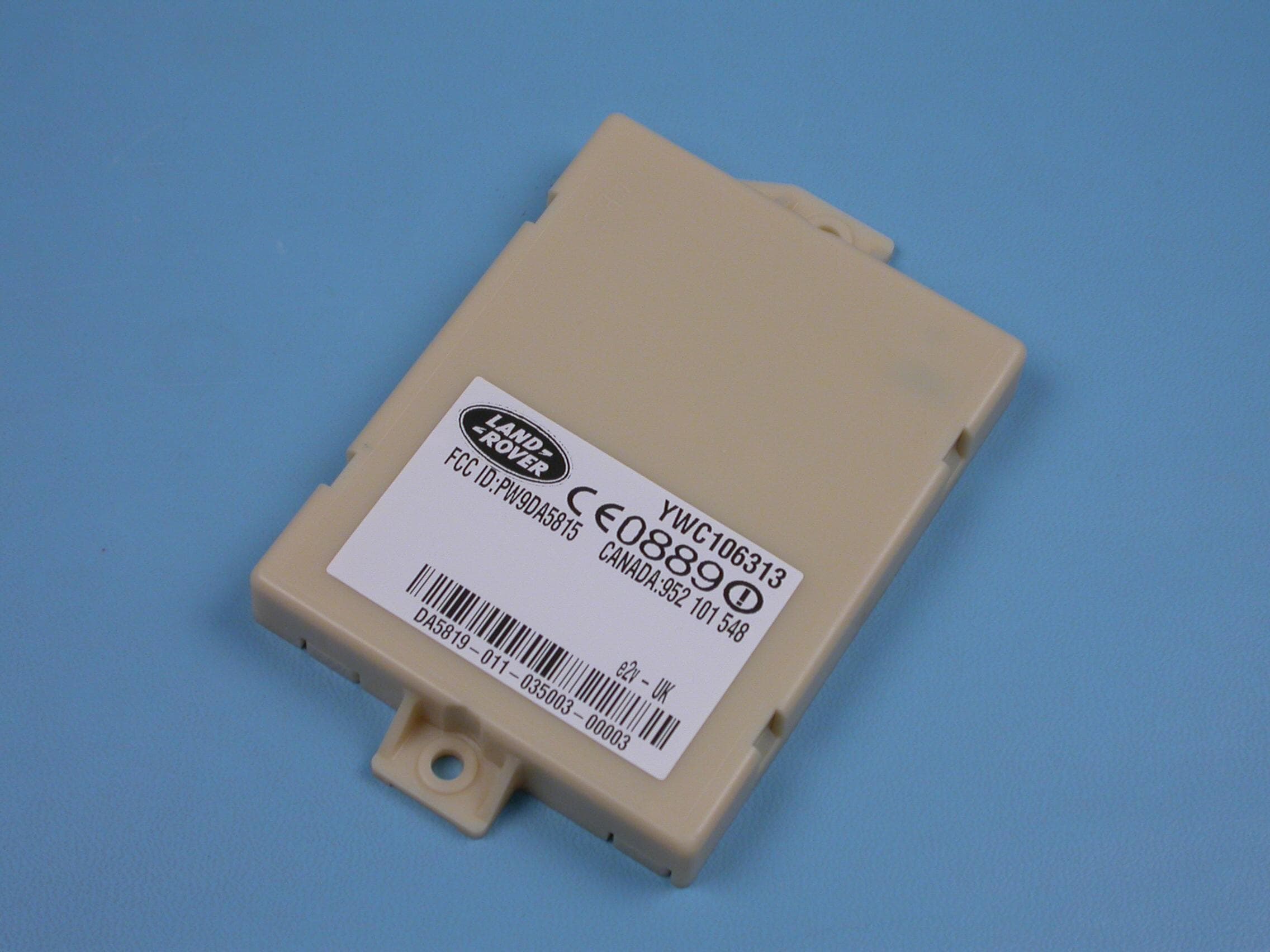
PW9DA5815
Jan 06, 2005Mass Movement Detector
Equipment Class
FDS - Part 15 Field Disturbance Sensor
PW9P4466-S-T2
Sep 03, 2003Argus� 3 P4466-S-T2 Thermal Imaging Camera
Equipment Class
TNB - Licensed Non-Broadcast Station Transmitter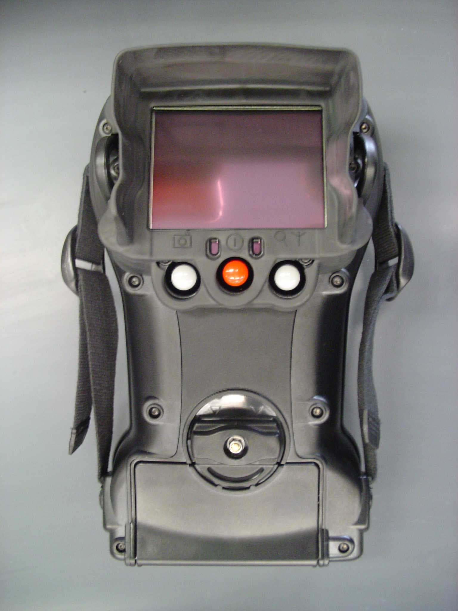
PW9P4467-T2
Sep 03, 2003Argus� 3 P4467-T2 Thermal Imaging Camera
Equipment Class
TNB - Licensed Non-Broadcast Station Transmitter
PW9P4467-S-T2
Sep 03, 2003Argus� 3 P4467-S-T2 Thermal Imaging Camera
Equipment Class
TNB - Licensed Non-Broadcast Station Transmitter
PW9P4466-T2
Sep 03, 2003Argus� 3 P4466-T2 Thermal Imaging Camera
Equipment Class
TNB - Licensed Non-Broadcast Station Transmitter