PWR1445004X-GL7XXGL700 Series Laser System
Trimble Inc.
Click to zoom
Application Details
- Equipment Class
- DSS - Part 15 Spread Spectrum Transmitter
- Date of Grant
- Feb 09, 2002
- Application Purpose
- Original Equipment
- Date of Application
- Feb 09, 2002
- Equipment Note
- GL700 Series Laser System
- Frequency Range
- 2402.00000000 - 2478.00000000
- Company
- Trimble Inc.
- Country
- United States
Documents & Files
Document Text
Text extracted from the exhibit documents filed with the FCC. Open a document above to read the original.
Users Manual
Trimble Model GL700 Series Laser Systems Operator’s Manual Single-Grade, Dual-Grade, Long-Range, and Steep-Grade Lasers Introduction Thank you for choosing one of the Spectra Precision Lasers from the Trimble family of precision grade lasers. You’ve just made a wise investment in field-proven products made by Trimble, the world’s largest manufacturer of laser-based leveling, alignment, and grade-control systems. The grade laser is an easy-to-use tool that allows you to take accurate horizontal measurements with grade up to 2500 ft (750 m) away using a receiver. The exclusive automatic alignment features allow for quick and easy setup. The exclusive temperature and grade compensation systems are designed for superior accuracy so that your grade laser can be used for ALL machine-control, general construction, and surveying applications requiring tight tolerances...under all environmental conditions. Included in this manual is information about setting up, using, maintaining, and troubleshooting the laser system. Use the manual now to learn basic skills, and use it later for reference. For the best performance of your laser system, follow the maintenance and care recommendations in this manual. Be sure to keep this manual in a convenient place for easy referencing. Your comments and suggestions are welcome; please call the Trimble Engineering and Construction Division listed below for your local, authorized Trimble office. Trimble 5475 Kellenburger Road Dayton, Ohio 45424-1099 U.S.A. Phone: (937) 233-8921 (800) 538-7800 Fax: (937) 233-9441 Internet: www.trimble.com Claim for Damage in Shipment The grade laser system generally includes a laser, remote control, receiver, general-purpose clamp, operator’s manual, laser safety kit, carrying case, rechargeable batteries, and battery recharger. The components vary depending on the system that you purchase. You should inspect your laser system as soon as you receive it. It has been packaged for safe delivery. If it is damaged in any way, immediately file a claim with the carrier or, if insured separately, with the insurance company. Owner’s Record Be sure to record the serial number of each component in the space provided below. Refer to these numbers if you need to contact your Trimble dealer regarding any of these products. Safety Information Included in this manual are CAUTIONS and Notes. Each of these words represents a level of danger or concern. A CAUTION indicates a hazard or an unsafe practice that could result in minor injury or property damage. A Note indicates important information unrelated to safety. Laser Safety The IEC and the United States Government Center of Devices for Radiology Health (CDRH) has classified this laser as a Class I laser product (standard model) and Class II product (long-range model). Operation For detailed installation and operating instructions, follow the instructions given in this manual for this laser. The maximum radiant power output of this laser is less than 5 mW. Controls Controls are listed in the operation section of this manual. CAUTION: Use of controls or adjustments performance of procedures other than those specified herein may result in higher dosage of laser exposure. This laser complies with all applicable portions of Title 21 of the code of Federal Regulations, Department of Health and Human Services, Food and Drug Administration (Federal Register, Volume 50, Number 161, August 20, 1985). Protective Eyewear This laser complies with OSHA Standards Act Section 1518.54 for use without eye protection devices. Consequently, protective eyewear is neither required nor recommended. As with any visible laser device, the following safety rules should be observed: • Never look directly into a laser beam or point the beam into the eyes of others. Set the laser at a height that prevents the beam from shining directly into people’s eyes. • Do not remove any warning signs from the laser. • Use of this product by people other than those trained on this product may result in exposure to hazardous laser light. • If initial service is required, which results in the removal of the outer protective cover, removal must only be performed by factory-trained personnel. Questions about laser safety should be addressed to: Trimble Engineering and Construction Division 5475 Kellenburger Road Dayton, OH U.S.A. 45424-1099 Attention: Quality Assurance Group, Laser Safety Officer Labels required for this product: • Certification and Identification: • Caution Logotype: Features and Functions Laser 1. Power Button—turns the laser on/off. 2. Status LED—shows the status of various conditions including an internal, electronic, or a mechanical error (solid red), low-battery (flashing yellow), manual mode (flashing red), HI alert (fast flashing red), and out-of-level (flashing green). 3. Manual Button—changes the laser from automatic self-leveling to manual mode. 4. ∠ Axis Up and Down Buttons—change the grade for the ∠ axis. 5. Rotation-Control Button—changes the laser beam rotation speed (300, 600, and 900 rpm). 6. ∠ Axis Up and Down Buttons (dual-grade laser only)—change the grade for the ∠ axis. 7. Axis-Alignment Buttons—rotates the grade axis clockwise/counterclockwise. Rotating the grade axis simulates turning the laser on its tripod, with fine adjustment capability. 8. Liquid Crystal Displays (LCDs)—show the percentage of grade, approximate charge of the batteries, beam's rotation speed, and axis alignment (if other than zero). The single-grade laser has one LCD. 9. Antenna (for radio remote-control lasers only)—sends and receives signals to and from the remote control. 10. Sunshade—protects the lighthouse from the environment. 11. Lighthouse—is the 360° exit window for the laser beam. The lighthouse is sealed and protects the internal components from the environment. 12. Rotor—contains the rotating laser beam. 13. Handle—allows you to carry the laser easily. 14. Battery Recharging Receptacle—is the 4-pin receptacle that the …
Text truncated - open the document above for the full version.
Block Diagram
BLOCK DIAGRAM – GL722 Antenna 2.4GHz Spread Spectrum Radio Battery Power Supply PCB External Connector Main PCB LCD Display Keyboard Y Vial Y Grade Motor Y Grade Mech- anics X Vial X Vial Mech- anics X Grade Motor Core Flashlight Laser Diode Y Level Mech- anics X Level Mechanics Y Level Motor X Level Motor Penta Prism Rotor Rotor Motor BLOCK DIAGRAM – RC70x Antenna 2.4GHz Spread Spectrum Radio Batteries Laser – Receiver Connector Main PCB LCD Display Keypad Power Supply
External Photos
GL722 SWITCHPANEL SIDE GL722 HANDLE SIDE GL722 BULKHEAD SIDE GL722 LABEL SIDE GL722 TOP VIEW GL722 BOTTOM VIEW GL722 INSIDE GL722 INSIDE GL722 INSIDE RC703 FRONT RC703 BACK/LABEL 1446-8900 BACK WITH RADIO 1446-8900 BACK WITHOUT RADIO
ID Label/Location Info
GL722 LABEL CLOSEUP GL722 LABEL SIDE RC703 LABEL CLOSEUP RC702 BACK
Internal Photos
1445-0900 BACK 1445-0900 FRONT (LCDs) 1445-0600 FRONT 1445-0600 BACK 1445 0500 FRONT 1445-0500 BACK 1445-0550 FRONT 1445-0550 BACK 1445-0600 BACK 1446-8900 FRONT 1445-9000 Front with LCDs removed 1445-0900 back with battery removed BACK NEW RADIO RADIO FRONT WITHOUT SHIELD NEW RADIO FRONT WITH SHIELD
Internal Photos
BACK NEW RADIO RADIO FRONT WITHOUT SHIELD NEW RADIO FRONT WITH SHIELD
Test Report
2.4 GHz FHSS OEM Transceiver Model No.: PKLR2400 FCC ID: KQL-PKLR2400 Applicant: AEROCOMM INC. 13256 West, 98th Street Lenexa, Kansas USA, 66215 Tested in Accordance With FCC Part 15, Subpart C, Para. 15.247 Frequency Hopping Spread Spectrum Transmitters Operating in Frequency Band from 2402 – 2478 MHz UltraTech's File No.: AER20-FTX This Test report is Issued under the Authority of Tri M. Luu, Professional Engineer, Vice President of Engineering UltraTech Group of Labs .................................................................. Date: ........................... Report Prepared by: Dan Huynh ................................................................... . Tested by: Hien Luu, RFI Technician .................................................................... Issued Date: August 23, 1999Test Dates: July 20-28, 1999 The results in this Test Report apply only to the sample(s) tested, and the sample tested is randomly selected. UltraTech 3000 Bristol Circle, Oakville, Ontario, Canada, L6H 6G4 Telephone (905) 829-1570 Facsimile (905) 829-8050 Website: www.ultratech-labs.com Email: [email protected] FCC PART 15, SUBPART C, SEC. 15.247 – FREQUENCY HOPPING SPREAD SPECTRUM TRANSMITTERSPage # 1 2.4 GHz FHSS OEM Transceiver, PKLR2400FCC ID: KQL-PKLR2400 ULTRATECH GROUP OF LABSFile #: AER20-FTX 3000 Bristol Circle, Oakville, Ontario, Canada L6H 6G4August 23, 1999 Tel. #: 905-829-1570, Fax. #: 905-829-8050, Email: [email protected], Website: http://www.ultratech-labs.com • Assessed by ITI (UK) Competent Body, NVLAP (USA) Accreditation Body & ACA/AUSTEL (Australia) • Recognized/Listed by FCC (USA), Industry Canada (Canada) • All test results contained in this engineering test report are traceable to National Institute of Standards and Technology (NIST) TABLE OF CONTENTS EXHIBIT 1.INTRODUCTION..............................................................................................................................3 1.1.SCOPE............................................................................................................................................................3 1.2.RELATED SUBMITAL(S)/GRANT(S)......................................................................................................................3 1.3.NORMATIVE REFERENCES........................................................................................................................3 EXHIBIT 2.PERFORMANCE ASSESSMENT....................................................................................................4 2.1.CLIENT INFORMATION..................................................................................................................................4 2.2.EQUIPMENT UNDER TEST (EUT) INFORMATION............................................................................................4 2.3.EUT’S TECHNICAL SPECIFICATIONS.......................................................................................................5 2.4.LIST OF EUT’S PORTS.......................................................................................................................................5 2.5.ANCILLARY EQUIPMENT....................................................................................................................................6 EXHIBIT 3.EUT OPERATING CONDITIONS AND CONFIGURATIONS DURING TESTS........................7 3.1.CLIMATE TEST CONDITIONS...............................................................................................................................7 3.2.OPERATIONAL TEST CONDITIONS & ARRANGEMENT FOR TESTS...........................................................................7 EXHIBIT 4.SUMMARY OF TEST RESULTS.....................................................................................................8 4.1.LOCATION OF TESTS..................................................................................................................................8 4.2.APPLICABILITY & SUMMARY OF EMC EMISSION TEST RESULTS...................................................................8 4.3.MODIFICATIONS INCORPORATED IN THE EUT FOR COMPLIANCE PURPOSES.............................................................8 EXHIBIT 5.MEASUREMENTS, EXAMINATIONS & TEST DATA FOR EMC EMISSIONS........................9 5.1.TEST PROCEDURES...........................................................................................................................................9 5.2.MEASUREMENT UNCERTAINTIES.........................................................................................................................9 5.3.MEASUREMENT EQUIPMENT USED:.....................................................................................................................9 5.4.ESSENTIAL/PRIMARY FUNCTIONS AS DECLARED BY THE MANUACTURER:..................................9 5.5.AC POWERLINE CONDUCTED EMISSIONS @ FCC PART 15, SUBPART B, PARA.15.107(A).................10 5.6.HOPPING CHANNEL CARRIER FREQUENCY CHARACTERISTICS @ FCC CFR 47, PARA 15.247(A)(1) & (A)(1)(II)11 5.6.1.Limits....................................................................................................................................................11 5.6.2.Method of Measurements.......................................................................................................................11 5.6.3.Test Arrangement..................................................................................................................................11 5.6.4.Test Equipment List...............................................................................................................................11 5.6.5.Test data................................................................................................................................................12 5.6.6.Plots.......................................................................................................................…
Text truncated - open the document above for the full version.
Test Setup Photos
Photograph of Test Setup: Radiated Emission (15.247) Photograph of Test Setup: Radiated Emission (15.247) Photograph of Test Setup: Radiated Emission (15.247) Photograph of Test Setup: Radiated Emission (15.247) Photograph of Test Setup: Radiated Emission (15.247)
Contact Information
Applicant
Ayman Hajmousa(Electronic Lead Engineer)
Test Firm
TUV AmericaJames Owen
Technical Specifications
| # | Rule Parts | Frequency Range | Power Output |
|---|---|---|---|
| 1 | 15C | 2.40 GHz - 2.48 GHz | 10.00 mW |
Other Applications from Trimble Inc.

PWR-TK14RF
Oct 30, 2014RF Module
Equipment Class
DTS - Digital Transmission System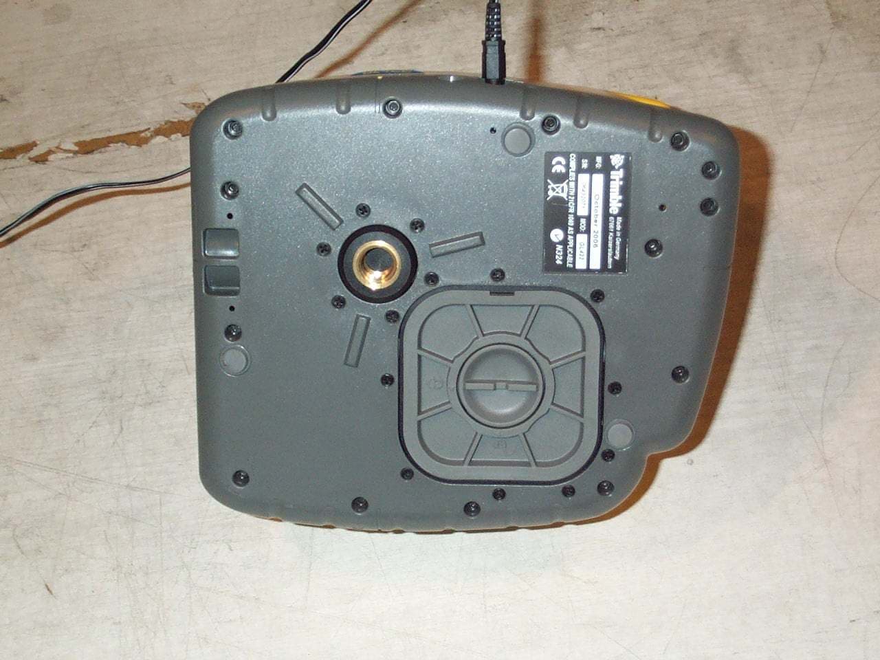
PWRGL4XX
Jan 30, 2007Lazer Level System
Equipment Class
DXT - Part 15 Low Power Transceiver, Rx Verified