PY20225HPDART-2400RT Wireless Interface
Xsilogy, Inc.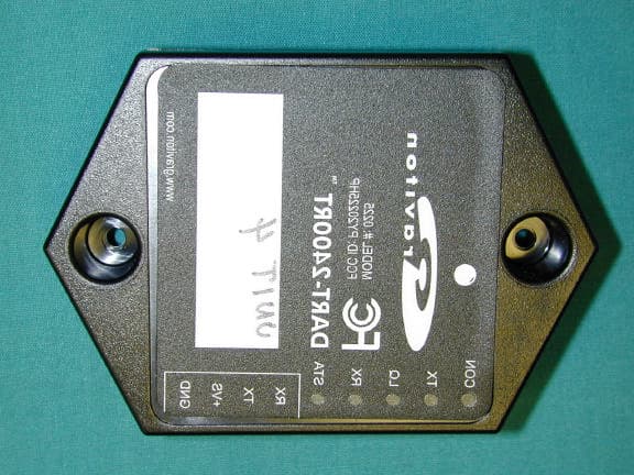
Click to zoom
Application Details
- Equipment Class
- DTS - Digital Transmission System
- Date of Grant
- Oct 10, 2002
- Application Purpose
- Original Equipment
- Date of Application
- Oct 10, 2002
- Equipment Note
- DART-2400RT Wireless Interface
- Frequency Range
- 2401.53000000 - 2476.47000000
- Company
- Xsilogy, Inc.
- Country
- United States
Documents & Files
Document Text
Text extracted from the exhibit documents filed with the FCC. Open a document above to read the original.
Users Manual
DART- 2400RT™ Installation Instructions and User’s Guide Preliminary Release October 9, 2002 ii Preliminary Release X1 DART™ Firmware Release 1.0 COPYRIGHT Copyright ©2002 Graviton, Inc. All Rights Reserved. No part of this document may be reproduced or transmitted in any form without the prior written consent of Graviton, Inc. Graviton Inc. transmitted in any form without the prior written consent of Graviton, 11025 North Torrey Pines Road, Ste. 200 San Diego 92037-1020 858-646-0774 Preliminary edition: February 2002 Printed in U.S.A. ACKNOWLEDGMENTS WINDOWS® and Internet Explorer are registered trademarks of Microsoft Corporation. NOTICE The information contained in this document is subject to change without notice. Graviton, Inc. assumes no responsibility for any errors that may appear in this document, nor does it make expressed or implied warranty of any kind with regard to this material, including, but not limited to, implied warranties of merchantability and fitness for a particular purpose. Graviton, Inc. shall not be liable for incidental or consequential damages in connection with, or arising out of the furnishing, performance, or use of this document and the hardware product and program material which it describes. Preliminary Release X1 1-1 Contents Regulatory Compliance Information.................1-2 Customer Support................................................1-6 1 Introduction...........................................1-6 Overview.................................................................1-6 About This Document..........................................1-9 Audience..........................................................1-9 2 Installation.............................................2-9 Before You Begin................................................2-10 Unpacking and Inventory............................2-10 Important Safety Precautions....................2-10 Parts Substitution.........................................2-11 Overview of Installation Steps..........................2-11 Hardware Installation Instructions...................2-11 DART-2400RT Front Panel...........................2-11 3 Using DART-2400RT (Operation)............1 4 Appendix...................................................2 Appendix A: Specifications...................................3 Appendix B – Signal Conditioner Input / Output Summary......................................................4 Introduction 1-2 Preliminary Release 1.0 Regulatory Compliance Information USA Changes or modifications not expressly approved by the party responsible for compliance could void the user's authority to operate the equipment. This device uses, generates, and radiates radio frequency energy. The radio frequency energy produced by this device is well below the maximum exposure allowed by the Federal Communications Commission(FCC). WARNING A minimum separation distance of 20 cm.(8 inches) must be maintained between the radiating element of the transmitter and nearby persons in order to ensure compliance with FCC rules for rf exposure. This transmitter must not be co-located with other transmitters or antenna This device complies with the limits for intentional radiator devices pursuant to Part 15 subpart C of the FCC Rules and Regulations. Operation is subject to the following two conditions: 1. This device must not cause harmful interference. 2. This device must accept any interference received, including interference that may cause undesired operation. The FCC limits are designed to provide reasonable protection against harmful interference when the equipment is installed and used in accordance with the instruction WARNING – Graviton components should only be installed by qualified personnel and should not be used in a manner inconsistent with prescribed practices. Whenever electrical voltages are involved, the risk of physical injury or equipment damage exists. Introduction Regulatory Compliance Information Preliminary Release 1.0 1-3 manual and operated in a commercial environment. However, there is no guarantee that interference will not occur in a particular commercial installation, or if operated in a residential area. If harmful interference with radio or television reception occurs when the device is turned on, the user must correct the situation at the user’s own expense. The user is encouraged to try one or more of the following corrective measures: ß Re-orient or relocate the receiving antenna. ß Increase the separation between the equipment and receiver. ß Connect the equipment into an outlet on a circuit different from that on which the receiver is connected. ß Consult the dealer or an experienced radio/TV technician for help. CANADA This device meets the requirements of RSS 210, Issue 3 To prevent radio interference to the licensed service, this device is intended to be operated indoors and away from windows to provide maximum shielding. Equipment (or its transmit antenna) that is installed outdoors is subject to licensing. EU Danish Undertegnede Graviton, Inc. erklærer herved, at følgende udstyr Wideband Transmission System Radio overholder de væsentlige krav og øvrige relevante krav i direktiv 1999/5/EF. 0470 ! Regulatory Compliance Information Introduction 1-4 Preliminary Release 1.0 Dutch Hierbij verklaart Graviton, Inc. dat het toestel [Wideband Transmission System Radio in overeenstemming is met de essentiële eisen en de andere relevante bepalingen van richtlijn 1999/5/EG. Bij deze verklaart [Naam van de fabrikant] dat deze [naam /type van het apparaat] voldoet aan de essentiële eisen en aan de overige relevante bepalingen van Richtlijn 1999/5/EC. English Hereby, Graviton, Inc., declares that this Wideband Transmission System Radio is in compliance with the essential requirements and other relevant provisions of Directive 1999/5/EC. German Hiermit erklärt Graviton, Inc., dass sich dieser/diese/dieses Wideband Transmission System Radio in Übereinstimmung mit den grundlegenden Anford…
Text truncated - open the document above for the full version.
Block Diagram
MSP430 Microcontroller RS-232 Level Translator LXT821 Radio Switching Power Supply 5 - 30 VDC Serial Device 3.6 V Reg. 3.3 V Reg. ID and Temp Sensor DART Block Diagram MSP430 Microcontroller LXT821 (single RF chip) Switching Power Supply 260 KHz Internal Oscillator DART Clock Diagram 7.3728 MHz Crystal 32.768 KHz Crystal 24 MHz Crystal 3.6864 MHz SPI clock 2401.53 MHz to 2476.47 MHz
Cover Letter(s)
PY20225HP
Cover Letter(s)
American Telecommunications Certification Body Inc. 6731 Whittier Ave, McLean, VA 22101 October 3, 2002 RE: FCC ID: PY20225HP Attention: Tom Tidwell I have a few comments on this Application. 1 The manual is not complete. Several sections are missing. These sections relate to where the device is used and how it is installed. Please provide these missing sections. 2 Please note, CFR47 Part 2.1033(b) (5) states, “A block diagram showing the frequency of all oscillators in the device. The signal path and frequency shall be indicated at each block. The tuning range(s) and intermediate frequency(ies) shall be indicated at each block.” Is required. Please note that the block diagram provided does not meet this requirement. Please provide a block diagram in accord with 2.1033(b)(5). xxx 3 No Schematic diagrams are provided. Please provide the schematics for this device. xxx 4 You state the device is a DSSS, however, no description of how this is a spread spectrum device has been provided. For example, the plots and other information may apply to a device that is simply an ultra wide FM modulated system. The maximum data through put as listed in the manual is only 19.2 kbps, thus questioning if the device meets the definition of a spread spectrum device. Please note that a DSSS is “A spread spectrum system in which the carrier has been modulated by a high speed spreading code and an information data stream. The high speed code sequence dominates the "modulating function" and is the direct cause of the wide spreading of the transmitted signal.” Please provide a technical description of why this is a DSSS device. xxx 5 Please note that as of Sept 9th, conducted emissions is from 150Khz. Unless you intend to apply under the transition clause 15.37 testing from 150kHz to 30MHz is applicable. Please indicate that you understand the implications of 15.37 as applicable to conducted emissions. xxx 6 You used radiated as the test method for determining power. However, you have not specified the antenna used in the system. While it does not appear to be an external antenna, you must clearly define the antenna used in a part 15 device. Also, your MPE calculations were done using 0dBi antenna gain yet states that a 15dBi+ gain antenna could be used. How is this possible? Please characterize the antenna used in testing this device. Please indicate that the antenna system complies with 15.203 antenna requirements. xxx 7 No indication has been presented that radiated emissions from 30MHz to 1000MHz has been performed. Please provide test data showing this frequency range has been tested. Alternately, please state that this range has been tested but no signals within 20dB were found. xxx 8 Please note that 15.247(c) is both a restricted band requirement in accordance with 15.209 and a band edge requirements whereby “In any 100 kHz bandwidth outside the frequency band in which the spread spectrum or digitally modulated intentional radiator is operating, the radio frequency power that is produced by the intentional radiator shall be at least 20 dB below that in the 100 kHz bandwidth within the band that contains the highest level of the desired power” (e.g. band edge compliance). While you have listed the limits of the restricted bands, you have not shown that the device meets the 20dB band edge limitation. Please provide objective evidence that the device meets the band edge requirements in addition to the restricted band requirements. xxx l Page 2October 3, 2002 Dennis Ward mailto:[email protected] The items indicated above must be submitted before processing can continue on the above referenced application. Failure to provide the requested information may result in application termination. Correspondence should be considered part of the permanent submission and may be viewed from the Internet after a Grant of Equipment Authorization is issued. Please do not respond to this correspondence using the email reply button. In order for your response to be processed expeditiously, you must submit your documents through the AmericanTCB.com website. Also, please note that partial responses increase processing time and should not be submitted. Any questions about the content of this correspondence should be directed to the sender.
Cover Letter(s)
Subject: RE: PY20225HP Date: Fri, 11 Oct 2002 15:35:36 -0500 From: [email protected] To: [email protected] CC: [email protected], [email protected] Dennis, Please see my responses below. Tom -----Original Message----- From: Dennis Ward [mailto:[email protected]] Sent: Friday, October 11, 2002 3:07 PM To: Tom Tidwell Subject: Re: PY20225HP Hi Tom I have reviewed the information you sent. There are a couple items. First, you provided the schematics (thanks) however, you did not provide a letter requesting confidentiality. If I issue the grant, I would have to upload the schematics in a non-confidential manner until a request for confidnetiality for the schematics was provided. I thought it better to get the letter first. As agent, you can write the letter specifying under 0.457 and 0.459 that you request confidentiality on the schematics and block/clock diagrams. Let me know. ANSWER: We sent a request in the original submission which I attach here. The schematics are the only document that needs confidentiality. Second, the manual gives a separation distance of 20cm then states 6 inches. This is obviously a typo, but needs correcting. The FCC is kinda picky about MPE separation distances and such. The statement should be 20cm (8 inches). ANSWER: I attach a revised manual. Third, (thanks for providing the missing sections) but the statement in the manual, "Do not use substitute parts or perform any unauthorized modification of equipment. This will void your warranty and may create an unworkable condition." does not address the requirements of 15.21 Information to the user. The statement must clearly inform the user that unauthorized modifications may void the users right to use the equipment. The FCC is not really interested if a warranty is voided or not, they are only interested in the user being informed that unauthorized modifications may void the right to use the equipment because it voids the ID fo the device. Generally it is just easier to cut and paste the words from 15.21(The users manual or instruction manual for an intentional or unintentional radiator shall caution the user that changes or modifications not expressly approved by the party responsible for compliance could void the user's authority to operate the equipment.). In any case, an appropriate non-modification statement must be in the manual. ANSWER: This has been corrected in the attached manual. I can issue the grant as soon as I have the above questions answered. Thanks Dennis [email protected] wrote: > Dennis, > > Could you confirm if you have received all that you need for this approval. > My client is asking for a completion date on it. > > Kind Regards, > > Tom --------------------------------------------------------------------- Name: RequestForConfidentiality.pdf RequestForConfidentiality.pdf Type: Acrobat (application/pdf) Encoding: base64 Name: DART Install and User GuideRev10-11-02.pdf DART Install and User GuideRev10-11-02.pdf Type: Acrobat (application/pdf) Encoding: base64
ID Label/Location Info
2.222 2.133 4X R 3.590 .141 .133 .142 PITCH 4X .240 5X .100 2X .520 1.600 .180 .190 .280 PITCH 3X .20 .061 .850 .25 www.graviton.com DART-2400RT TM MODEL #: 0225 FCC ID: PY20225HP BLACK BACKGROUND COLOR LOGO COLOR: WHITE FONT: FUTURA EXTRABOLD COLOR: FONT: FUTURA EXTRABOLD PT11 CHARACTORS ALL OTHER TEXT: WHITE, ARIAL PT 6 CHARACTORS STA RX LQ TX CON +VS GND 2X WHITE FILL RX TX SCALE:1:1 SIZE DWG. NO. A REV. MATERIAL FINISH -- -- DO NOT SCALE DRAWING APPLICATION USED ON NEXT ASSY DIMENSIONS ARE IN INCHES TOLERANCES: ANGULAR: 1.0 DEGREE ONE PLACE DECIMAL: .1 TWO PLACE DECIMAL: .01 THREE PLACE DECIMAL: .005 NAME DATE DRAWN CHECKED ENG APPR. MFG APPR. Q.A. SHEET 1 OF 1 WEIGHT: COMMENTS: REVISIONS DESCRIPTION REV. DATE THE INFORMATION CONTAINED IN THIS DRAWING IS THE SOLE PROPERTY OF <INSERT COMPANY NAME HERE>. ANY REPRODUCTION IN PART OR AS A WHOLE WITHOUT THE WRITTEN PERMISSION OF <INSERT COMPANY NAME HERE> IS PROHIBITED. PROPRIETARY AND CONFIDENTIAL ZONE 11025 N. Torrey Pines Rd La Jolla, CA 92037-1030 R.HARRIS R.HARRIS C.GARRET B.GUEST J.FARENBAUGH 092-000121-01 X2 X1 PRELIMINARY, RELEASE FOR RFQ 4/11/02 013-000400-00 LABEL, TOP PROJ. ENGD.RHODES__/__/__ __/__/__ __/__/__ __/__/__ __/__/__ 4/11/02 X2 RELEASE FOR RFQ (COMPLETE RE-DESIGN) 5/6/02
Operational Description
DART Theory of Operation The DART product is an RS-232 to RF translator designed to interface to a serial device. The radio operates in the 2.4 GHz band and is powered by a 10 - 30 VDC power supply. Any RS232 data received on the RX pin will be transmitted via the radio to a Graviton Multi-Services Gateway (MSG). Any data received from an MSG via the radio will be retransmitted on the TX pin on the serial interface.
Operational Description
ALPINE LXT821 Spread Spectrum Digital Cordless Telephone Transceiver Revision 4.3Confidential Contains Proprietary InformationPage 1 of 68 11/03/00 Reproduction Unauthorized Without Written Consent November 2000 General Description The ALPINE (LXT 821) is a single chip spread spectrum RF transceiver designed for use in 2.4 GHz Spread Spectrum Digital Cordless Telephone (SSDCT) applications. ALPINE is fully compliant with the FCC Part 15 2.4 GHz ISM band spectrum regulations. Based on CMOS technology, ALPINE integrates a complete FM transceiver suitable for direct sequence spread spectrum applications. ALPINE includes a 2.4 GHz synthesizer, transmit power amplifier, receive low noise amplifier, antenna switch, channel select filtering, FSK demodulator, and a complete TDD burst-mode controller with forward error correction in a single integrated circuit. ALPINE can be combined with an ADPCM CODEC and a micro-controller to create a complete SSDCT terminal. No other ICs are required. The LXT 821 performs all multiplexing / de-multiplexing and spreading / de-spreading functions required to transmit a 32k b/s ADPCM voice signal and 4k b/s data channel over a 2.4 GHz radio link. Applications • Spread Spectrum Digital Cordless Telephones • Wireless security and monitoring transceivers • Wireless Spread Spectrum Data/Voice Transceivers Features • Single chip wireless transceiver: RF in, Data out • 2.4 GHz ISM band compliant, 2.4015 to 2.4780 GHz • Performs all RF transceiver functions on-chip: RF Power Amplifier with 1 to 100 mW output FSK Modulator Synthesizer/Oscillator LNA All Channel Filtering FSK Data Demodulator TDD Burst Mode Controller Receive Signal Strength Indicator (Receiver Gain) • Very low external component count (<30 discretes) • No external RF switches required due to TDD format • 3.0 to 3.6 Volt operation • Typical current consumption ~ 190 mA average current at maximum transmit power • Allows for adaptive far end transmit power control • 1.5 M Chip/s spread data rate • 2.0 mS Time Division Duplex (TDD) frame rate for reduced side-tone delay • 32k b/s voice and 4k b/s data channel provides high quality voice and high speed supervisory link between base and handset • Industry standard SPI bus for control of all functions • 0 to 70 C temperature range • Package: 64 pin TQFP ALPINE Block Diagram FSK Modem/ Spreader/ De-spreader RF Receiver RF Transmitter Synthesizer TDD Burst- Mode Controller/ Timing Generator ADPCM FIFO Buffer MCU Interface and Clock Generator RF I/O 2.40-2.48 GHz SPI BUS uC I/O uC CLK Out IRQ Out XTALO XTALI TXADPCM RXADPCM PCMCLK PCMSYNC CODECCLK PWRDWN RFP RFN ALPINE LXT821 Spread Spectrum Digital Cordless Telephone Transceiver Revision 4.3Confidential Contains Proprietary InformationPage 2 of 68 11/03/00 Reproduction Unauthorized Without Written Consent November 2000 1. Revision History Revision Number DateOriginatorRevision description 1.011/18/99C. NilsonInitial Revision from LXT 820 Rev 1.4 and LXT 801 Rev 2.1 1.111/30/99C. NilsonRevised pin names and descriptions to correspond to LXT810 2.04/30/00D. JonesUpdate to B1 Revision, add sections on Pin Signal Muxing and Channel Coding 3.06/22/00D. Jones E. Dukatz A. Dickinson Major Revision of Register Descriptions, Pin Signal Descriptions, added Register Descriptions for new Auto-mute control via Window Path Metric. 3.16/25/00D. JonesAdd description of IRQ timing in Slave search mode Update A1 to B1 changes list 3.26/28/00L. PlouvierAdd full registers description, update definition, defaults and recommendations 4.09/21/00E. DukatzBased on Rev 4.1 Design Specification 4.19/25/00E. DukatzCorrected Crystal Specification and FRMCTRL register description 4.210/14/00E. DukatzRevised Specifications 4.311/3/00E. DukatzChanged lowest channel frequency and frequency deviation specification to provide margin on FCC spec. ALPINE LXT821 Spread Spectrum Digital Cordless Telephone Transceiver Revision 4.3Confidential Contains Proprietary InformationPage 3 of 68 11/03/00 Reproduction Unauthorized Without Written Consent November 2000 2. Table of Contents: 1.Revision History ............................................................................................................................................................................................ 2 2.Table of Contents: ......................................................................................................................................................................................... 3 3.List of Figures................................................................................................................................................................................................ 5 4.List of Tables ................................................................................................................................................................................................. 5 5.Introduction ................................................................................................................................................................................................... 6 5.1The ALPINE Spread Spectrum Digital Cordless Telephone RF Transceiver ................................................................................................. 6 5.2Operation Overview.............................................................................................................................................................................................. 6 6.Pin Assignments and Signal Descriptions .................................................................................................................................................... 9 6.1Package Description.............................................................................................................................................................................................. 9 6.2RF Interface Pins ....................................…
Text truncated - open the document above for the full version.
Contact Information
Applicant
Kenneth J Sherman(Vice President, Engineering)
Technical Contact
Nemko Dallas, Inc.David Light
[email protected]972-436-9600
802 N Kealy Rd. · Lewisville, Texas · United States
Non-Technical Contact
Nemko Dallas, Inc.Tom Tidwell
[email protected]972-436-9600
Test Firm
Nemko Dallas, Inc.Michael Cantwell
Technical Specifications
| # | Rule Parts | Frequency Range | Power Output |
|---|---|---|---|
| 1 | 15C | 2.40 GHz - 2.48 GHz | 128.83 mW |
Other Applications from Xsilogy, Inc.
PY20229HP
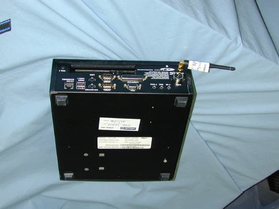
Sep 11, 2002Multi-Services Gateway
Equipment Class
DSS - Part 15 Spread Spectrum Transmitter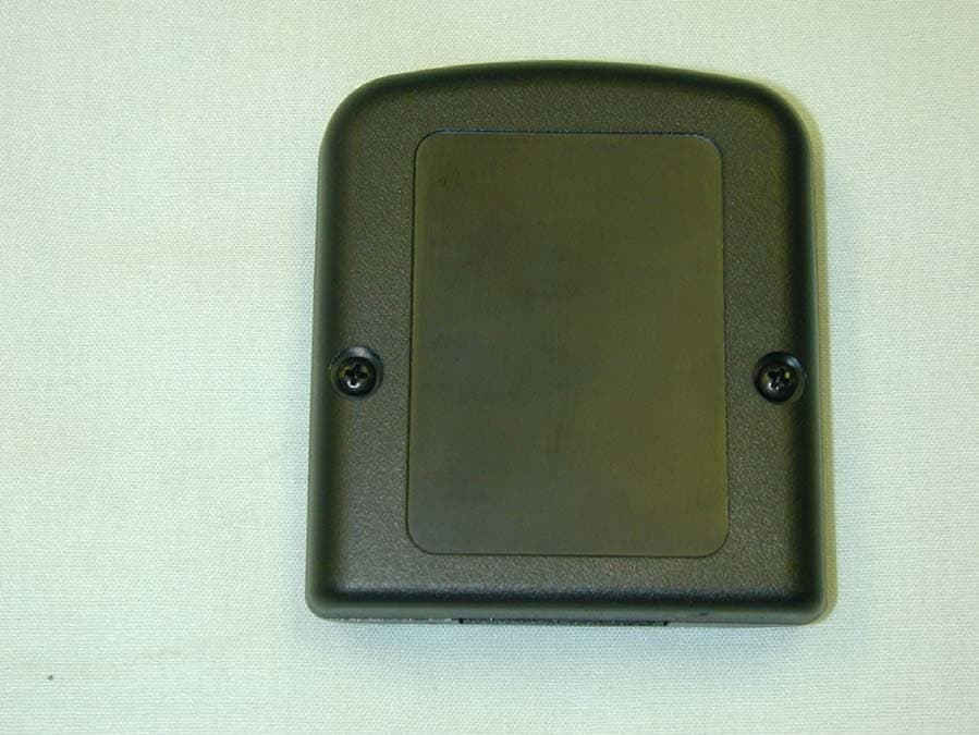
PY20920HP
Apr 11, 2002Battery Monitoring System
Equipment Class
DSS - Part 15 Spread Spectrum Transmitter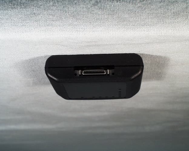
PY20920
Mar 31, 2002Model: 0920
Equipment Class
DSS - Part 15 Spread Spectrum Transmitter