PY20920Model: 0920
Xsilogy, Inc.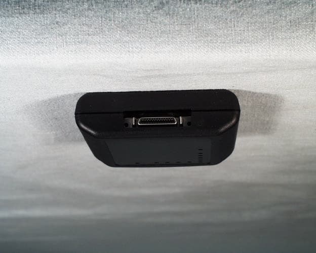
Click to zoom
Application Details
- Equipment Class
- DSS - Part 15 Spread Spectrum Transmitter
- Date of Grant
- Mar 31, 2002
- Application Purpose
- Original Equipment
- Date of Application
- Mar 31, 2002
- Equipment Note
- Model: 0920
- Frequency Range
- 2401.50000000 - 2478.00000000
- Company
- Xsilogy, Inc.
- Country
- United States
Documents & Files
Document Text
Text extracted from the exhibit documents filed with the FCC. Open a document above to read the original.
Users Manual
BattGuard™ Installation Instructions and User’s Guide PRELIMINARY Release X1 February 2002 WARNING: Battery systems have the potential to cause severe burns, shocks, and other serious injuries. Graviton, Inc. strongly advises that only persons specifically trained in the techniques and procedures necessary to ensure personal safety while working with high-energy batteries install or maintain the BattGuard battery monitoring system. ii Preliminary Release X1 BattGuard™ Release X1 COPYRIGHT Copyright ©2002 Graviton, Inc. All Rights Reserved. No part of this document may be reproduced or transmitted in any form without the prior written consent of Graviton, Inc. Graviton, Inc. 9820 Towne Centre Drive San Diego, CA 92121-1974 858.646.0774 www.graviton.com Preliminary edition: February 2002 Printed in U.S.A. ACKNOWLEDGMENTS WINDOWS® and Internet Explorer are registered trademarks of Microsoft Corporation. NOTICE The information contained in this document is subject to change without notice. Graviton, Inc. assumes no responsibility for any errors that may appear in this document, nor does it make expressed or implied warranty of any kind with regard to this material, including, but not limited to, implied warranties of merchantability and fitness for a particular purpose. Graviton, Inc. shall not be liable for incidental or consequential damages in connection with, or arising out of the furnishing, performance, or use of this document and the hardware product and program material which it describes. Preliminary Release X1 iii Contents 1 Introduction..............................................1-1 Welcome..........................................................................1-1 About This Document .....................................................1-1 Audience ...................................................................1-1 Notes and Warnings .................................................1-2 FCC Compliance Information.........................................1-2 Customer Support............................................................1-3 2 Installation................................................2-1 Before You Begin............................................................2-1 Unpacking and Inventory .........................................2-1 Important Safety Precautions ...................................2-2 Overview of Installation Steps........................................2-3 Hardware Installation Instructions..................................2-3 Telesensor Installation Procedure ............................2-4 BattGuard Telesensor Front Panel ...........................2-6 End-of-String Master Installation Procedure...........2-7 Software Installation Instructions ...................................2-7 Hardware Requirements...........................................2-7 Software Requirements ............................................2-8 Software Installation Procedure ...............................2-8 Verifying the BattGuard Software Installation........2-8 3 Using BattGuard......................................3-1 Understanding the BattGuard Screen .............................3-1 The Data Tab ............................................................3-1 The Alarms Tab........................................................3-2 The Unknown Telesensors Tab ...............................3-3 Charting Voltages and Temperature...............................3-4 Monitoring Alarms..........................................................3-5 Exporting Data ................................................................3-6 Contents iv Preliminary Release X1 4 Setting Up Battery Strings .....................4-1 Telesensors Installed – On-Line Configuration .............4-1 Telesensors Not Installed – Off-Line Configuration......4-4 Modifying and Deleting String Settings .........................4-7 5 Setting Up Alarms ...................................5-1 6 Appendices ..............................................6-1 Appendix A – Battery Diagnostics .................................6-3 Appendix B – IEEE Recommended Battery Maintenance Programs....................................................6-5 Vented Lead-Acid Batteries for Stationary Applications (Flooded Batteries) (IEEE STD 450-1995)..................................................................6-5 Valve-Regulated Lead-Acid (VRLA) Batteries for Stationary Applications (IEEE STD 1188- 1996) .........................................................................6-6 Preliminary Release X1 1-1 1 Introduction Welcome With the BattGuard™ Battery Monitoring System, you’ll be able to continuously monitor the health of the individual batteries used in your battery back-up system. You will have assurance that they will function properly when you need them most – during a power outage. BattGuard includes the following components: BattGuard Telesensors – specially designed transceivers that are connected to each battery cell in your backup system and monitor the health of your backup system. The Telesensors measure voltage, current and temperature and transmit the data every 15 minutes using a performance optimized 2.4GHz direct sequence spread spectrum (DSSS) radio. End-of-String master – special Telesensor that receives the battery data from the Telesensors and provides a radio to serial (PC) interface. DCU (Data Collection Unit) – laptop computer that collects the following data for each battery: battery current measurements, voltage, and temperature. BattGuard software – specialized computer program used to configure the Telesensors, graphically display battery data, and export the data for further analysis using other programs such as Microsoft Excel. About This Document This guide includes procedures to help you install and use the BattGuard Battery Monitoring System. Audience Information in this guide is directed to field engineers and technicians, customer engineers, technicians, and contracted installa…
Text truncated - open the document above for the full version.
External Photos
Front View of the 0920 Back View of the 0920 Side View of the 0920
ID Label/Location Info
0.30 .01 43.37 1.71 59.37 2.34 4X R 3.68 .15 4.70 .19 CLEAR TRANSPARENT MATERIAL 5X 3.22 .13 0 0 4.29 .17 9.37 .37 14.45 .57 19.53 .77 24.61 .97 40.64 1.60 13.21 .52 2.87 .11 3.20 .13 33.53 1.32 4.83 .19 MODEL #: 0920 FCC ID: PY20920 CON TX LQ RX STA BattGuard Telesensor CUSTOMER CARE: 1-866-217-3182 ALL OTHER TEXT: WHITE, ARIAL PT 6 CHARACTORS TM LOGO: COLOR: (ALL) WHITE FONT: FUTURA EXTRABOLD BLACK BACKGROUND COLOR: WHITE FONT: FUTURA EXTRABOLD PT 11 CHARACTORS GRAVITON INC. SCALE:1:1 SIZEDWG. NO. A REV. MATERIAL FINISH -- -- DO NOT SCALE DRAWINGAPPLICATION USED ONNEXT ASSY DIMENSIONS ARE IN INCHES TOLERANCES: FRACTIONAL ANGULAR: MACH BEND TWO PLACE DECIMAL THREE PLACE DECIMAL NAME DATE DRAWN CHECKED ENG APPR. MFG APPR. Q.A. SHEET 1 OF 1WEIGHT: COMMENTS: REVISIONS DESCRIPTION REV. DATEAPPROVED THE INFORMATION CONTAINED IN THIS DRAWING IS THE SOLE PROPERTY OF <INSERT COMPANY NAME HERE>. ANY REPRODUCTION IN PART OR AS A WHOLE WITHOUT THE WRITTEN PERMISSION OF <INSERT COMPANY NAME HERE> IS PROHIBITED. PROPRIETARY AND CONFIDENTIAL ZONE R.HARRIS 2/22/02 X1 Label Top Enclosure W/FCC 092-000116-01
Internal Photos
Front View of the 0920 PCB Front View of the 0920 PCB With Shield Removed Back View of the 0920 PCB
RF Exposure Info
Exhibit 11: RF Exposure/Environmental Section 15.247 (b)(4) Requirement: Spread spectrum devices shall be operated in a manner that ensures that the public is not exposed to radio frequency energy levels in excess of the Commission’s guidelines. See § 1.1307(b) and 2.1093 of this chapter. All equipment shall be considered to operate in a “general population/uncontrolled” environment. Applications for equipment authorization of devices operating under this section must contain a statement confirming compliance with these requirements for both fundamental emissions and unwanted emissions. Technical information showing the basis for this statement must be submitted to the Commission upon request. Demonstration of Compliance: The 0920 is classified as a mobile device, which is installed so that a minimum separation distance of 20 centimeters in maintained between the transmitter’s radiating structure and the body of the user or nearby persons, and the ERP of the 0920 is less than 50 mWatts. Therefore, the 0920 is categorically excluded from routine environmental evaluation for RF exposure as per § 2.1093. The installation/user manual contains a warning statement that instructs the installer/user that the 20 centimeter separation distance must be maintained in order to comply with the RF exposure requirement.
Test Report
TEST REPORT FROM: COMMUNICATION CERTIFICATION LABORATORY 1940 W. Alexander Street Salt Lake City, Utah 84119-2039 Type of Report: Certification TEST OF: 0920 FCC ID: PY20920 To FCC PART 15.247, Subpart C Test Report Serial No: 73-7720 Applicant: Graviton, Inc. 11025 North Torrey Pines Road Suite 200 La Jolla, CA 92037 Date(s) of Test: March 1 st & 4 th , 2002 Issue Date: March 15, 2002 Equipment Receipt Date: March 1, 2002 COMMUNICATION CERTIFICATION LABORATORY TEST REPORT: 73-7720 FCC ID: PY20920 Page 2 of 56 CERTIFICATION OF ENGINEERING REPORT This report has been prepared by Communication Certification Laboratory to determine compliance of the device described below with the requirements of FCC PART 15.247, Subpart C. This report may be reproduced in full, partial reproduction may only be made with the written consent of the laboratory. The results in this report apply only to the sample tested. - Applicant: Graviton, Inc. - Manufacturer: Graviton, Inc. - Brand Name: Graviton - Model Number: 0920 - FCC ID: PY20920 On this 15 th day of March, 2002 I, individually, and for Communication Certification Laboratory, certify that the statements made in this engineering report are true, complete, and correct to the best of my knowledge, and are made in good faith. COMMUNICATION CERTIFICATION LABORATORY _________________________ Tested by: Kirk P. Thomas Project Engineer COMMUNICATION CERTIFICATION LABORATORY TEST REPORT: 73-7720 FCC ID: PY20920 Page 3 of 56 TABLE OF CONTENTS SECTION 1. CLIENT INFORMATION AND RESPONSIBLE PARTY:.......4 SECTION 2. EQUIPMENT UNDER TEST (EUT)......................5 SECTION 3. TEST SPECIFICATION, METHODS & PROCEDURES........8 SECTION 4. OPERATION OF EUT DURING TESTING................14 SECTION 5. SUMMARY OF TEST RESULTS:.......................15 SECTION 6. MEASUREMENTS, EXAMINATIONS AND DERIVED RESULTS:...............................................16 APPENDIX 1 TEST PROCEDURES AND TEST EQUIPMENT..............39 APPENDIX 2 PHOTOGRAPHS.....................................47 COMMUNICATION CERTIFICATION LABORATORY TEST REPORT: 73-7720 FCC ID: PY20920 Page 4 of 56 SECTION 1. CLIENT INFORMATION AND RESPONSIBLE PARTY: 1.1 Applicant: Company Name: Graviton, Inc. 11025 North Torrey Pines Road Suite 200 La Jolla, CA 92037 Contact Name: Don Hohnstein Title: Director 1.2 Manufacturer: Company Name: Graviton, Inc. 11025 North Torrey Pines Road Suite 200 La Jolla, CA 92037 Contact Name: Don Hohnstein Title: Director COMMUNICATION CERTIFICATION LABORATORY TEST REPORT: 73-7720 FCC ID: PY20920 Page 5 of 56 SECTION 2. EQUIPMENT UNDER TEST (EUT) 2.1 Identification of EUT: Trade Name: Graviton Model Name or Number: 0920 Serial Number: N/A Country of Manufacture: U.S.A. 2.2 Description of EUT: The 0920 consists of at least two transievers. One transiever is connected to each battery cell in a battery backup system and monitors the health of the backup system. The 0920 measure voltage, current and temperature and transmit the data every 15 minutes using a 2.4GHz direct sequence spread spectrum (DSSS) radio. The battery data is received by the second tranceiver, that provides a radio to serial (PC) interface. This report covers the transmitter portion of the device only the receiver/computer peripheral is covered under a separate declaration of conformity report. 2.3 Modification Incorporated/Special Accessories on EUT: There were no modifications or special accessories required to comply with the specification. COMMUNICATION CERTIFICATION LABORATORY TEST REPORT: 73-7720 FCC ID: PY20920 Page 6 of 56 2.4 EUT and Support Equipment: The FCC ID numbers for all the EUT and support equipment used during the test (including inserted cards) are listed below: Brand Name Model Number Serial No. FCC ID Number Description Name of Interface Ports / Interface Cables BN: Graviton MN: 0920 (1) PY20920 2.4 GHz Tranciever See Sec 2.5. BN: Micron MN: NBKV370 DOC Laptop Computer Serial / 2 foot serial cable Note: (1) EUT. (2) Interface port connected to EUT (See Section 2.4) (3) Mouse cable permanently attached. (4) Monitor’s attached video cable includes manufacturer-supplied ferrite. The support equipment listed above was not modified in order to achieve compliance with this standard. 2.5 Interface Ports on EUT: Name of Port No. of Ports Fitted to EUT. Cable Descriptions/Length Antenna 1 Soldered directly to PCB Serial 1 Mini serial to RS232 / 2 foot COMMUNICATION CERTIFICATION LABORATORY TEST REPORT: 73-7720 FCC ID: PY20920 Page 7 of 56 2.6 Channels of Operation: The 0920 operates on the following channels: Channel Number Channel Frequency (MHz) Channel Number Channel Frequency (MHz) 1 2401.50 27 2440.50 2 2403.00 28 2442.00 3 2404.50 29 2443.50 4 2406.00 30 2445.00 5 2407.50 31 2446.50 6 2409.00 32 2448.00 7 2410.50 33 2449.50 8 2412.00 34 2451.00 9 2413.50 35 2452.50 10 2415.00 36 2454.00 11 2416.50 37 2455.50 12 2418.00 38 2457.00 13 2419.50 39 2458.50 14 2421.00 40 2460.00 15 2422.50 41 2461.50 16 2424.00 42 2463.00 17 2425.50 43 2464.50 18 2427.00 44 2466.00 19 2428.50 45 2467.50 20 2430.00 46 2469.00 21 2431.50 47 2470.50 22 2433.00 48 2472.00 23 2434.50 49 2473.50 24 2436.00 50 2475.00 25 2437.50 51 2476.50 26 2439.00 52 2478.00 COMMUNICATION CERTIFICATION LABORATORY TEST REPORT: 73-7720 FCC ID: PY20920 Page 8 of 56 SECTION 3. TEST SPECIFICATION, METHODS & PROCEDURES 3.1 Test Specification: Title: FCC PART 15.247, Subpart C (47 CFR 15). Limits and methods of measurement of radio interference characteristics of radio frequency devices. Operation within the bands 902-928 MHz, 2400-2483.5 MHz and 5725-5850 MHz. Purpose of Test: The tests were performed to demonstrate Initial compliance. 3.2 Methods & Procedures: 3.2.1 §15.247 (a) Operation under the provisions of this section is limited to frequency hopping and direct sequence spread spectrum intentional radiators that comply with the following provisions: (1) Frequency hoping systems shall have hopping channel carrier frequencies separated by a mi…
Text truncated - open the document above for the full version.
Test Report
LXT821B1 Processing Gain Test Results 4/2/02 Processing Gain Measurement: LXT821B1 (Alpine B1) Revised: 2/28/2002 Page 1 of 5 LXT821B1 Processing Gain Test Results 4/2/02 I. Summary This document describes how the processing gain was measured for the Intel LXT821B1 digital spread spectrum telephone transceiver. Included are specifications, test setup, and test results. II. Requirements According to the FCC requirement 15.247 for direct sequence spread spectrum systems, the minimum processing gain is 10 dB. The CW jamming method was used to determine the LXT821B1 processing gain. The processing gain was calculated using the following equation: G p = S/I + J/S + L sys where: G p = Processing Gain S/I = Signal to noise required for a given error probability. In this case 1 x 10 -4 was used. J/S = Jammer to signal ratio required to produce given error probability. L sys = System loss to due non ideal performance. Maximum allowed by the FCC is 2.0 dB. The S/I ratio was determined to be 11.0 dB according to Jakes “Microwave Mobile Communications”. Page 229 indicates the relevant curve showing error probability Vs S/I for a non-coherent FM system with a peak deviation equal to .35 of the modulation frequency: F d = .35 F s . Given a minimum processing gain of 10 dB, the minimum allowable J/S ratio is -3.0 dB. Page 2 of 5 LXT821B1 Processing Gain Test Results 4/2/02 III. Test Setup The processing gain was measured using the test setup shown in Figure 1: DUT: LXT821: Slave Mode RF I/O RF Shielded Enclosure Bit Error Rate Tester Receive Data Signal Generator: 2.439 - 2.442 GHz Tranmit Data Tranmit Data ClockReceived Data Clock Spectrum Analyzer LXT821: Master Mode RF I/O 10 dB Directional Coupler In Out Cpl Step Attenuator: 0 to 120 dB, 1db Steps Power Combiner / Splitter s 12 Master Unit: RF Signal Slave Unit: RF Signal 10 dB Directional Coupler In OutCpl Figure 1: Processing Gain Test Setup The following test equipment was used for this setup: • LDB810 Demonstration system: Used LXT821B1 RFIC’s. • Hewlett Packard ESG D3000A Signal Generator • Hewlett Packard HP8563E Spectrum Analyzer • Hewlett Packard HP 8494A and HP 8496A Step Attenuators • Mini Circuits ZFDC-10-5 10 dB Directional Coupler (2) • Mini Circuits ZFSC-2-4 Power Combiner • Ramsey STE-3000 Shielded Test Enclosure • Telecommunication Techniques Corp. Firebird MC6000 Communication Analyzer (BER tester) with Lab Interface Card • Semflex SMA cables The LDB810 demonstration system was set up at the middle channel 2.4405GHz. The LXT810B base band 3dB bandwidth is less than 1.0 MHz; therefore, the signal generator was used to inject a C / W jammer from 2.439GHz to 2.442GHz in 50 kHz increments. The DUT received input power was set at -50 dBm. The jammer power was adjusted to achieve a bit error rate of 1x10⁻⁴ at each jammer frequency. The jammer power was recorded and the processing gain calculated for each jammer frequency from 2.439GHz to 2.442GHz. IV. Test Results The worst case processing gain found for the middle frequency band was 11.4 dB for the jamming frequency of 2.4411GHz, and 11.5dB for the jamming frequency of 2.439.9GHz. This and all Page 3 of 5 LXT821B1 Processing Gain Test Results 4/2/02 other jamming frequencies in the middle of the band (2.439GHz-2.442GHz) pass the minimum requirement of 10dB. All of the measured test data is recorded in : : Channel Frequency (Nominal) = 2440.50 MHz Bit Error Rate = 1.00E-04 Required S/N for BER = 11.0 dB System Losses = 2.0 dB Desired Signal Strength at Receiver (S) = -50.0 dBm Jammer to Signal Ratio Jammer Frequency (MHz) RF Src pwr Jammer Power (J) (dBm) J / S (dB) Processing Gain (dB) 2439.000 -21.80 -28.30 21.7 34.7 2439.050 -22.80 -29.30 20.7 33.7 2439.100 -24.00 -30.50 19.5 32.5 2439.150 -25.20 -31.70 18.3 31.3 2439.200 -26.40 -32.90 17.1 30.1 2439.250 -27.70 -34.20 15.8 28.8 2439.300 -29.10 -35.60 14.4 27.4 2439.350 -30.70 -37.20 12.8 25.8 2439.400 -32.10 -38.60 11.4 24.4 2439.450 -34.40 -40.90 9.1 22.1 2439.500 -36.40 -42.90 7.1 20.1 2439.550 -38.20 -44.70 5.3 18.3 2439.600 -39.90 -46.40 3.6 16.6 2439.650 -41.50 -48.00 2.0 15.0 2439.700 -43.30 -49.80 0.2 13.2 2439.750 -44.20 -50.70 -0.7 12.3 2439.800 -44.50 -51.00 -1.0 12.0 2439.850 -44.80 -51.30 -1.3 11.7 2439.900 -45.00 -51.50 -1.5 11.5 2439.950 -44.90 -51.40 -1.4 11.6 2440.000 -44.70 -51.20 -1.2 11.8 2440.050 -44.70 -51.20 -1.2 11.8 2440.100 -44.70 -51.20 -1.2 11.8 2440.150 -44.50 -51.00 -1.0 12.0 2440.200 -44.20 -50.70 -0.7 12.3 2440.250 -44.20 -50.70 -0.7 12.3 2440.300 -44.00 -50.50 -0.5 12.5 2440.350 -44.00 -50.50 -0.5 12.5 2440.400 -43.90 -50.40 -0.4 12.6 2440.450 -44.10 -50.60 -0.6 12.4 2440.470 -43.20 -49.70 0.3 13.3 2440.480 -42.40 -48.90 1.1 14.1 2440.490 -42.60 -49.10 0.9 13.9 2440.495 -42.80 -49.30 0.7 13.7 Page 4 of 5 LXT821B1 Processing Gain Test Results 4/2/02 2440.500 -42.60 -49.10 0.9 13.9 2440.505 -42.60 -49.10 0.9 13.9 2440.510 -42.80 -49.30 0.7 13.7 2440.520 -43.60 -50.10 -0.1 12.9 2440.530 -43.90 -50.40 -0.4 12.6 2440.550 -43.80 -50.30 -0.3 12.7 2440.600 -42.90 -49.40 0.6 13.6 2440.650 -43.10 -49.60 0.4 13.4 2440.700 -43.40 -49.90 0.1 13.1 2440.750 -43.70 -50.20 -0.2 12.8 2440.800 -44.00 -50.50 -0.5 12.5 2440.850 -44.40 -50.90 -0.9 12.1 2440.900 -44.70 -51.20 -1.2 11.8 2440.950 -44.80 -51.30 -1.3 11.7 2441.000 -45.00 -51.50 -1.5 11.5 2441.050 -45.00 -51.50 -1.5 11.5 2441.100 -45.10 -51.60 -1.6 11.4 2441.150 -44.90 -51.40 -1.4 11.6 2441.200 -44.90 -51.40 -1.4 11.6 2441.250 -43.90 -50.40 -0.4 12.6 2441.300 -42.40 -48.90 1.1 14.1 2441.350 -40.80 -47.30 2.7 15.7 2441.400 -39.00 -45.50 4.5 17.5 2441.450 -37.20 -43.70 6.3 19.3 2441.500 -35.20 -41.70 8.3 21.3 2441.550 -33.20 -39.70 10.3 23.3 2441.600 -31.40 -37.90 12.1 25.1 2441.650 -29.90 -36.40 13.6 26.6 2441.700 -28.10 -34.60 15.4 28.4 2441.750 -26.80 -33.30 16.7 29.7 2441.800 -25.30 -31.80 18.2 31.2 2441.850 -24.10 -30.60 19.4 32.4 2441.900 -22.80 -29.30 20.7 33.7 2441.950 -21.70 -28.20 21.8 34.8 2442.000 -20.60 -27.10 22.9 35.9 11.4 = Minimum Processing Gain 2.…
Text truncated - open the document above for the full version.
Test Setup Photos
Front view of the test setup Back view of the test setup
Contact Information
Applicant
Kenneth J Sherman(Vice President, Engineering)
Technical Contact
Graviton, Inc.Don Hohnstein
[email protected]858 909 2180
11025 North Torrey Pines Road · La Jolla, California · United States
Test Firm
Communication Certification Lab.Scott Earl
Technical Specifications
| # | Rule Parts | Frequency Range | Power Output |
|---|---|---|---|
| 1 | 15C | 2.40 GHz - 2.48 GHz | 11.40 mW |
Other Applications from Xsilogy, Inc.
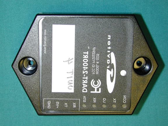
PY20225HP
Oct 10, 2002DART-2400RT Wireless Interface
Equipment Class
DTS - Digital Transmission System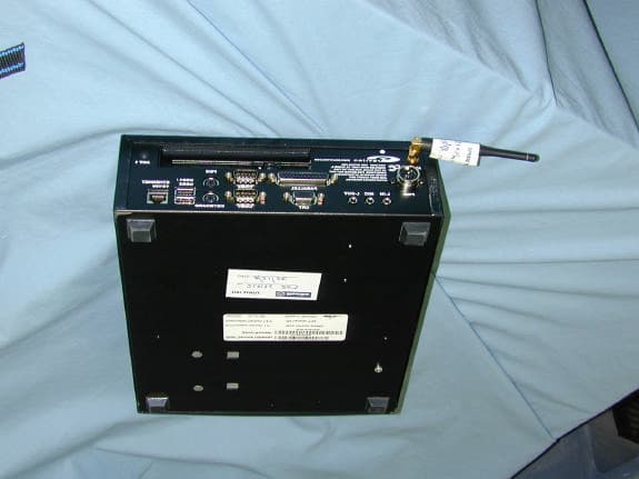
PY20229HP
Sep 11, 2002Multi-Services Gateway
Equipment Class
DSS - Part 15 Spread Spectrum Transmitter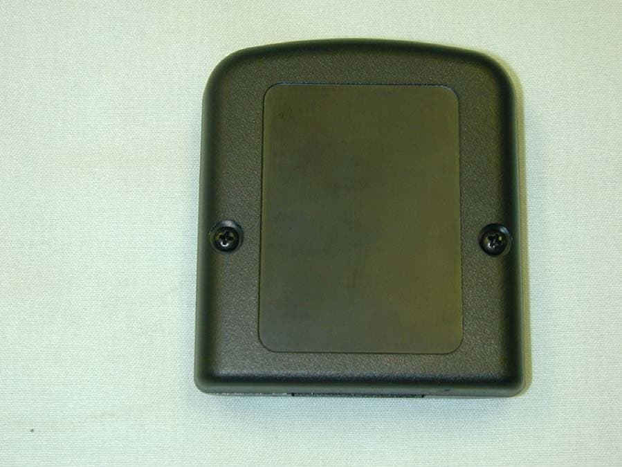
PY20920HP
Apr 11, 2002Battery Monitoring System
Equipment Class
DSS - Part 15 Spread Spectrum Transmitter