PY20229HPMulti-Services Gateway
Xsilogy, Inc.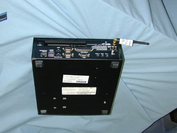
Click to zoom
Application Details
- Equipment Class
- DSS - Part 15 Spread Spectrum Transmitter
- Date of Grant
- Sep 11, 2002
- Application Purpose
- Original Equipment
- Date of Application
- Sep 11, 2002
- Equipment Note
- Multi-Services Gateway
- Frequency Range
- 2401.40000000 - 2479.50000000
- Company
- Xsilogy, Inc.
- Country
- United States
Documents & Files
Document Text
Text extracted from the exhibit documents filed with the FCC. Open a document above to read the original.
Block Diagram
11.0592MHZ Crystal BALUN 2.400-2.480 BPF Controller (SOC) Radio (RF ASIC) 24 MHZ Crystal (+/- 30ppm) Power Supply Circuits Analog Inputs Serial I/O (115200 b/s typ.) DC Power (5.5 - 40V Battery) Antenna (On board) fvco = 3,000,000[ 16(128-M)+(31-A)/2 ] A = 0 to 32 M= 77 or 78 Where: (M <= 32 + A) 2403.0 - 2479.5 MHz (DSSS 1.5 Mc/s) (1.5 MHz Channels) Modulation: FM (525kHz typ.) P N Data Rate =32k b/s data (+4k b/s control) IF (Direct Conversion) 260k Hz
Cover Letter(s)
Subject: RE: PY20229HP Date: Thu, 12 Sep 2002 10:02:15 -0500 From: [email protected] To: [email protected] Dennis, The MPE only lists the maximum gain for reference. The only antenna to be used with the radio is the "rubber ducky" antenna is used. The manufacturer lists the antenna gain as 0 dBi. The antenna connector and the TX port connector are unique connectors so no other unauthorized antenna could be used. Tom -----Original Message----- From: Dennis Ward [mailto:[email protected]] Sent: Wednesday, September 11, 2002 3:28 PM To: Tom Tidwell Subject: Re: PY20229HP HI Tom The antenna gain used in the MPE report was 0dBi. However, the max antenna gain in the MPE report states 18dBi. Please remember that unless that antenna has been tested and shown to comply with the radiated spurious emissions, it will not be on the grant. THe EMC report was not specific on which antenna was used, however, from the data it appears that a 1.4 dipole was used. This would not be a 0dBi antenna since it is a dipole and has directionality over isotropic. Please specify what the gain of the antenna used during radiated spurious emissions was. Remember, only those antennae tested will be allowed for this device. If the manufacturer has a high gain antenna for this device, it should be tested for compliance now so it can be included in the application. I will issue the grant after you have provided the gain of the antenna used during testing. Thanks Dennis Thanks Dennis [email protected] wrote: > Just the schematics is fine. > > Tom > > -----Original Message----- > From: Dennis Ward [mailto:[email protected]] > Sent: Wednesday, September 11, 2002 11:31 AM > To: Tom Tidwell > Subject: Re: PY20229HP > > Hi Tom > The schematics are the only thing listed as confidential. If you want the > technical description and the block diagram as confidential, please revise > the > confidentialailty request to include these. > Thanks > Dennis > > [email protected] wrote: > > > Dennis, > > > > I have uploaded the external photos exhibit. > > > > The master does not set the frequency of the slave. The radios do not hop > > frequency either. > > > > Could you please verify for me that I marked the schematics as > confidential. > > I am not sure that I did. > > > > Thanks, > > > > Tom > > > > -----Original Message----- > > From: Dennis Ward [mailto:[email protected]] > > Sent: Tuesday, September 10, 2002 8:14 PM > > To: Tom Tidwell > > Subject: Re: PY20229HP > > > > Hi Tom > > I will be doing this. I noticed however, that you did not provide > external > > photos for the application. Please provide these external ohotos. I think > > once I get them, I can isue the grant failry quickly. > > > > I do have one question after a cursory looksee. The application speaks of > a > > master slave relationship between transmitters. Does the master determine > > the > > frequency the slave is to operate on? This may be a problem since DSSS > must > > be psudorandom and having another device predetermine a frequency is not > > good. I will reivew the app in more detail, but if youahve a quick > answer, > > that might help. > > > > thanks > > Dennis > > > > [email protected] wrote: > > > > > Dennis, > > > > > > Do you know the status of this one? It is for Graviton. I am not sure > if > > > you have this one or not but it was uploaded 8/29. > > > > > > Tom
External Photos
Label location
ID Label/Location Info
9.388 238.450 2.940 74.680 MSG-0229 FOR OFFICE USE. COMPLIES WITH PART 15, CLASS A, OF FCC RULES, SUBJECT TO TWO CONDITIONS: THIS DEVICE MAY NOT CAUSE HARMFUL INTERFERENCE AND MUST ACCEPT ANY INTERFERENCE RECEIVED. FCC ID: PY20229HP IC: 4300A-0229HP ANT 2 ANT 1 L-IN L-OUT MIC COM1 CRT KEYBOARD USB1 / USB2ETHERNET 10/100 PS/2 ARIAL BLACK, 6PT ALL OTHER TEXT: ARIAL BLACK, 9PT THE INFORMATION CONTAINED IN THIS DRAWING IS THE SOLE PROPERTY OF GRAVITON, INC. ANY REPRODUCTION IN PART OR AS A WHOLE WITHOUT THE WRITTEN PERMISSION OF GRAVITON, INC. IS PROHIBITED. COM2 PARALLEL PWR MSG-0229 FOR OFFICE USE. COMPLIES WITH PART 15, CLASS A, OF FCC RULES, SUBJECT TO TWO CONDITIONS: THIS DEVICE MAY NOT CAUSE HARMFUL INTERFERENCE AND MUST ACCEPT ANY INTERFERENCE RECEIVED. FCC ID: PY20229HP IC: 4300A-0229HP WWW.GRAVITON.COM D C B A A B C D SIZE DWG. NO. D REV 1 2 345 6 7 8 8765 4 321 E F E F THE INFORMATION CONTAINED IN THIS DRAWING IS THE SOLE PROPERTY OF <INSERT COMPANY NAME HERE>. ANY REPRODUCTION IN PART OR AS A WHOLE WITHOUT THE WRITTEN PERMISSION OF <INSERT COMPANY NAME HERE> IS PROHIBITED. PROPRIETARY AND CONFIDENTIAL SCALE: 1:1SHEET 3 OF 6 WEIGHT: -- REV -- D 11025 N. Torrey Pines Rd La Jolla, CA 92037-1030 093-000110-00 D
Internal Photos
MSG Top View Radio Board mounted in MSG Radio Board - Bottom Radio Board –Bottom with Shield Removed Radio Board Top Radio Board – Close-up under shield Radio Board – Data/Power Connector RF Output Connector – Reverse Gender SMA Antenna Connector – Reverse Gender SMA Antenna mounted on MSG
Operational Description
tech.descr.doc 8/29/02 May Contain Proprietary Information 1 of 5 Theory of Operation For the Model 0229HP 1. Introduction. The Model 0229HP Radio is a low power, 2.4GHz Direct Sequence Spread Spectrum (DSSS) telemetry transceiver (or Telesensor) intended for monitoring of industrial battery systems. Intended operating frequencies are in the unlicensed Industrial Scientific and Medical (ISM) band. A Telesensor consists of a highly integrated RF ASIC and mixed signal System on a Chip (SOC) microcontroller. A typical installation consists of several Telesensors controlled by a single master or WAN gateway product as shown in Figure 1. In its simplest form one telesensor assumes the role of the master and is connected into a Personal Computer (PC) or similar monitoring device. TelesensorTelesensorTelesensor MasterCOM Figure 1 Typical System 2. Operation. The block diagram is shown in Figure 2. Data gathered by the SOC via the analog input interface are stored. The SOC also controls the RF ASIC. A Phase Lock Loop (PLL) voltage controlled oscillator (VCO) internal to the RF ASIC accomplishes the frequency control. All of the frequencies are derived from a 24MHz crystal controlled reference oscillator. Since the receiver uses a direct conversion to base band, the VCO simply tunes to the center frequency. tech.descr.doc 8/29/02 May Contain Proprietary Information 2 of 5 11.0592MHZ Crystal BALUN 2.400-2.480 BPF Controller (SOC) Radio (RF ASIC) 24 MHZ Crystal (+/- 30ppm) Power Supply Circuits Analog Inputs Serial I/O (115200 b/s typ.) DC Power (5.5 - 40V Battery) fvco = 3,000,000[ 16(128-M)+(31-A)/2 ] A = 0 to 32 M= 77 or 78 Where: (M <= 32 + A) 2403.0 - 2479.5 MHz (DSSS 1.5 Mc/s) (1.5 MHz Channels) Modulation: FM (525kHz typ.) P N Data Rate =32k b/s data (+4k b/s control) IF (Direct Conversion) 260k Hz Figure 2 Block Diagram The center frequency of operation is determined PLL reference, which is divided by two internal counters (A and M). Table 1 shows the valid range of operation of the VCO. Table 1 PLL Programming Channel Freq (MHz) Fref (MHz) M count A count 1 2403.00 24 78 29 2 2404.50 24 78 28 3 2406.00 24 78 27 4 2407.50 24 78 26 5 2409.00 24 78 25 6 2410.50 24 78 24 7 2412.00 24 78 23 8 2413.50 24 78 22 9 2415.00 24 78 21 10 2416.50 24 78 20 11 2418.00 24 78 19 12 2419.50 24 78 18 13 2421.00 24 78 17 14 2422.50 24 78 16 15 2424.00 24 78 15 16 2425.50 24 78 14 17 2427.00 24 78 13 18 2428.50 24 78 12 19 2430.00 24 78 11 20 2431.50 24 78 10 21 2433.00 24 78 9 22 2434.50 24 78 8 23 2436.00 24 78 7 24 2437.50 24 78 6 25 2439.00 24 78 5 26 2440.50 24 78 4 27 2442.00 24 78 3 28 2443.50 24 78 2 tech.descr.doc 8/29/02 May Contain Proprietary Information 3 of 5 Channel Freq (MHz) Fref (MHz) M count A count 29 2445.00 24 78 1 30 2446.50 24 78 0 31 2448.00 24 77 31 32 2449.50 24 77 30 33 2451.00 24 77 29 34 2452.50 24 77 28 35 2454.00 24 77 27 36 2455.50 24 77 26 37 2457.00 24 77 25 38 2458.50 24 77 24 39 2460.00 24 77 23 40 2461.50 24 77 22 41 2463.00 24 77 21 42 2464.50 24 77 20 43 2466.00 24 77 19 44 2467.50 24 77 18 45 2469.00 24 77 17 46 2470.50 24 77 16 47 2472.00 24 77 15 48 2473.50 24 77 14 49 2475.00 24 77 13 50 2476.50 24 77 12 51 2478.00 24 77 11 52 2479.50 24 77 10 Actual data is transferred 8-bytes at a time at a 32k bits-per-second (bps) data rate. The receiver continues scanning the channel list until a master is detected. The transmitters spread the data using a Pseudorandom Numerical (PN) sequence with a chipping rate of 1.5Megachips per second. When the receiver locks to the PN sequence it can read the control channel and determine if the sampled data can be sent. The master only occupies any single channel for a predetermined number of milliseconds before switching to a new frequency. Data is transferred in a Time Division Duplex (TDD) format only transmitting 50% in any given frame. The frame consists of two data packets: a 12-bit preamble, an 8-bit sync byte, and an 8-bit control byte. The packet also includes a 4-bit CRC post amble. A data diagram is shown in Figure 3. Once in sync, the slave begins to transmit, the master locks to the slaves PN sequence, and master and slave alternately transmit for approximately 1 millisecond in the 2 milliseconds long frame. A total of 96 bits are transmitted and transferred in each packet. tech.descr.doc 8/29/02 May Contain Proprietary Information 4 of 5 12-bit Preamble 8-bit Sync 8-bit Data 64-bit Data Payload 4- bit 1288 64-bit Data Payload 41288 64-bit Data Payload 4 1288 64-bit Data Payload 41288 64-bit Data Payload 4 Master: Transmit Receive TransmitReceive Slave: 960 uS 2000 uS 12 12 120 uS 40 us Earliest Expected arrival from Slave 50 us Latest Expected arrival From Slave ( @ 1- mile distance from Master ) Figure 3 Data Frame Format In actual operation, the system periodically (several minutes typically) the SOC wakes up and tunes the receiver to various channels in search of a master. The system is designed to allow only one master/telesensor pair to be transmitting at any given time. A controlling node (master) is periodically beaconing on each channel in the ISM band. The master transmitter either ready to accept a new telesensor on a channel or is currently communicating with one. The status is communicated in the 8-bit control channel. After the data is transferred the telesensor switches off its transmitter and goes back to sleep mode. The master also stops transmitting on this channel and retunes to another channel, this prevents any one channel from being used on a continuous basis, and if the channel is clear the master begins beaconing for the next telesensor. If no telesensors are found within a certain time interval, the master will again change its beaconing frequency. 3. Channels. The Model 920 divides up the allotted ISM band into 51 channels each approximately 1.5 MHz wide. The actual channels of operation within the ISM band are shown in Table 2. tech.descr.doc 8/29/02 May Contain Proprietary Information 5 of 5 Table …
Text truncated - open the document above for the full version.
RF Exposure Info
Prediction of MPE limit at a given distance Equation from page 18 of OET Bulletin 65, Edition 97-01 where:S = power density P = power input to the antenna G = power gain of the antenna in the direction of interest relative to an isotropic radiator R = distance to the center of radiation of the antenna Maximum peak output power at antenna input terminal:19.00(dBm) Maximum peak output power at antenna input terminal:79.43282347(mW) Antenna gain(typical):0(dBi) Maximum antenna gain:1(numeric) Prediction distance:20(cm) Prediction frequency:2400(MHz) MPE limit for uncontrolled exposure at prediction frequency:1(mW/cm^2) Power density at prediction frequency:0.015803(mW/cm^2) Maximum allowable antenna gain:18.01269855(dBi) 2 4R PG S π =
Test Report
Nemko Test Report:2L0135RUS1 Applicant:Graviton 9820 Towne Centre Drive San Diego, CA 92121 Equipment Under Test:MSG with Internal RPC (E.U.T.)Model#: 0229 In Accordance With:FCC Part 15, Subpart C, 15.247 Direct Sequence Spread Spectrum Transmitters Tested By:Nemko Dallas Inc. 802 N. Kealy Lewisville, Texas 75057-3136 Authorized By: David Light, Senior Wireless Technician Date: Total Number of Pages:34 Nemko Dallas FCC PART 15, SUBPART C DIRECT SEQUENCE SPREAD SPECTRUM TRANSMITTER EQUIPMENT: MSG w/ Internal RPC Model 0229PROJECT NO.:2L0135RUS1 Page 2 of43 Table of Contents Section 1. Summary of Test Results .........................................................................3 Section 2. Equipment Under Test (E.U.T.) ..............................................................5 Section 3. Powerline Conducted Emissions .............................................................7 Section 4. Minimum 6 dB Bandwidth ....................................................................11 Section 5. Maximum Peak Output Power...............................................................15 Section 6. RF Exposure ..........................................................................................16 Section 7. Spurious Emissions (radiated) ...............................................................17 Section 8. Spurious Emissions (Antenna Conducted) ............................................21 Section 9. Peak Power Spectral Density .................................................................26 Section 10. Test Equipment List .............................................................................30 ANNEX A - TEST DETAILS .................................................................................31 ANNEX B - TEST DIAGRAMS.............................................................................41 Nemko Dallas FCC PART 15, SUBPART C DIRECT SEQUENCE SPREAD SPECTRUM TRANSMITTER EQUIPMENT: MSG w/ Internal RPC Model 0229PROJECT NO.:2L0135RUS1 Page 3 of43 Section 1.Summary of Test Results Manufacturer:Graviton Name:MSG-0229 Model No.:0229 Serial No.:Sample #01 General:All measurements are traceable to national standards. These tests were conducted on a sample of the equipment for the purpose of demonstrating compliance with Part 15, Subpart C, Paragraph 15.247 for Direct Sequence Spread Spectrum devices. Radiated tests were conducted is accordance with ANSI C63.4-1992. Radiated emissions are made on an open area test site. A description of the test facility is on file with the FCC. New SubmissionProduction Unit Class II Permissive ChangePre-Production Unit THIS TEST REPORT RELATES ONLY TO THE ITEM(S) TESTED. THE FOLLOWING DEVIATIONS FROM, ADDITIONS TO, OR EXCLUSIONS FROM THE TEST SPECIFICATIONS HAVE BEEN MADE. None See “ Summary of Test Data”. NVLAP LAB CODE: 100426-0 Nemko Dallas Inc. authorizes the above named company to reproduce this report provided it is reproduced in its entirety and for use by the company’s employees only. Any use which a third party makes of this report, or any reliance on or decisions to be made based on it, are the responsibility of such third parties. Nemko Dallas Inc. accepts no responsibility for damages, if any, suffered by any third party as a result of decisions made or actions based on this report. This report applies only to the items tested. Nemko Dallas FCC PART 15, SUBPART C DIRECT SEQUENCE SPREAD SPECTRUM TRANSMITTER EQUIPMENT: MSG w/ Internal RPC Model 0229PROJECT NO.:2L0135RUS1 Page 4 of43 Summary Of Test Data NAME OF TESTPARA. NO.SPEC.RESULT Powerline Conducted Emissions15.207(a) 48 dBμV Complies Minimum 6 dB Bandwidth15.247(a)(2)>500 kHzComplies Maximum Peak Power Output15.247(b)(1)<1 WattComplies Spurious Emissions (Antenna Conducted) 15.247(c)-20 dBc/100kHzComplies Spurious Emissions (Restricted Bands) 15.247(c) < 74 dBuV/m Peak < 54 dBuV/m Avg Complies Peak Power Spectral Density15.247(d)+8 dBm/3kHzComplies Footnotes: Nemko Dallas FCC PART 15, SUBPART C DIRECT SEQUENCE SPREAD SPECTRUM TRANSMITTER EQUIPMENT: MSG w/ Internal RPC Model 0229PROJECT NO.:2L0135RUS1 Page 5 of43 Section 2.Equipment Under Test (E.U.T.) General Equipment Information Frequency Band: 902 – 928 MHz 2410 – 2479 MHz 5725 – 5850 MHz User Frequency Adjustment: Software controlled Nemko Dallas FCC PART 15, SUBPART C DIRECT SEQUENCE SPREAD SPECTRUM TRANSMITTER EQUIPMENT: MSG w/ Internal RPC Model 0229PROJECT NO.:2L0135RUS1 Page 6 of43 Theory of Operation The MSG-0229 is a Multi-Services Gateway product that includes a computer platform with a wireless data radio operating in the 2.4 – 2.4835 GHz ISM band. The radio rf output is a reverse SMA connector and the antenna provided with the unit has the matching connector. System Diagram MSG Platform 0229 Ra dio Reverse SMA connector Nemko Dallas FCC PART 15, SUBPART C DIRECT SEQUENCE SPREAD SPECTRUM TRANSMITTER EQUIPMENT: MSG w/ Internal RPC Model 0229PROJECT NO.:2L0135RUS1 Page 7 of43 Section 3.Powerline Conducted Emissions NAME OF TEST: Powerline Conducted EmissionsPARA. NO.: 15.207 TESTED BY: Tom TidwellDATE: 8/28/2002 Test Results:Complies. Measurement Data: .450 MHz – 30 MHz48 dBuV Nemko Dallas FCC PART 15, SUBPART C DIRECT SEQUENCE SPREAD SPECTRUM TRANSMITTER EQUIPMENT: MSG w/ Internal RPC Model 0229PROJECT NO.:2L0135RUS1 Page 8 of43 Dallas Headquarters: 802 N. Kealy Lewisville, TX 75057 Tel: (972) 436-9600 NEMKO Dallas, Inc.Fax: (972) 436-2667 Conducted Emissions Powerline Voltage Measurement CompleteXJob # : 2L0135RTest # : CEPV-01 PreliminaryPage1of2 Client Name :GRAVITON EUT Name :MSG with internal RPC EUT Model # :229 EUT Part # :NA EUT Serial # :NA EUT Config. :TX @ MID BAND Specification :15.207 Reference : Transducer # :545Temp. (deg. C) :24Date : 8/29/02 HP Filter # :1555Humidity (%) :40Time : 13:00 Cable 1 # :1547EUT Voltage :115Staff : TNT Cable 2 # :1114EUT Frequency :60Location : LAB 4 Detector 1 # :1036Peak Bandwidth:10kHzPhoto ID: NA Detector 2 # :QP Bandwidth10kHz Limiter # :674Avg. Bandwi…
Text truncated - open the document above for the full version.
Contact Information
Applicant
Kenneth J Sherman(Vice President, Engineering)
Technical Contact
Nemko Dallas, Inc.David Light
[email protected]972-436-9600
802 N Kealy Rd. · Lewisville, Texas · United States
Non-Technical Contact
Nemko Dallas, Inc.Tom Tidwell
[email protected]972-436-9600
Test Firm
Nemko Dallas, Inc.Michael Cantwell
Technical Specifications
| # | Rule Parts | Frequency Range | Power Output |
|---|---|---|---|
| 1 | 15C | 2.40 GHz - 2.48 GHz | 79.40 mW |
Other Applications from Xsilogy, Inc.
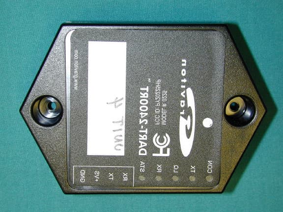
PY20225HP
Oct 10, 2002DART-2400RT Wireless Interface
Equipment Class
DTS - Digital Transmission System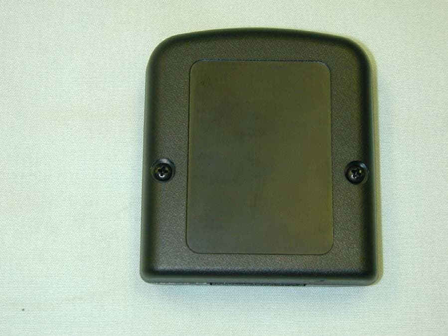
PY20920HP
Apr 11, 2002Battery Monitoring System
Equipment Class
DSS - Part 15 Spread Spectrum Transmitter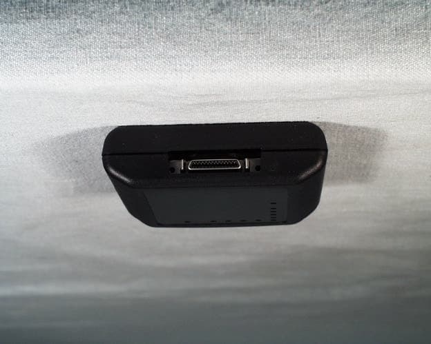
PY20920
Mar 31, 2002Model: 0920
Equipment Class
DSS - Part 15 Spread Spectrum Transmitter