PY30510000254 Mbps Wireless Router
Netgear Incorporated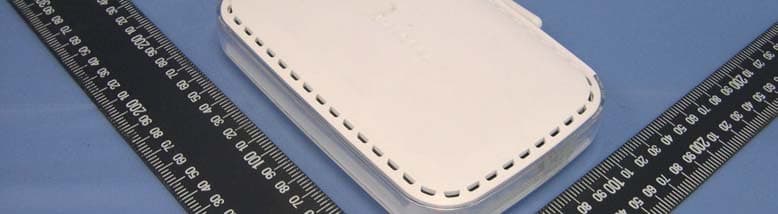
Click to zoom
Application Details
- Equipment Class
- DTS - Digital Transmission System
- Date of Grant
- Mar 28, 2005
- Application Purpose
- Original Equipment
- Date of Application
- Mar 28, 2005
- Equipment Note
- 54 Mbps Wireless Router
- Frequency Range
- 2412.00000000 - 2462.00000000
- Company
- Netgear Incorporated
- Country
- United States
Documents & Files
Document Text
Text extracted from the exhibit documents filed with the FCC. Open a document above to read the original.
Users Manual
July 2004 202-10036-01 202-10036-01 Version 1.5 July 2004 NETGEAR, Inc. 4500 Great America Parkway Santa Clara, CA 95054 USA Reference Manual for the 54 Mbps Wireless Router WGR614 v6 ii July 2004 202-10036-01 © 2004 by NETGEAR, Inc. All rights reserved. July 2004. Trademarks NETGEAR is a trademark of Netgear, Inc. Microsoft, Windows, and Windows NT are registered trademarks of Microsoft Corporation. Other brand and product names are registered trademarks or trademarks of their respective holders. Statement of Conditions In the interest of improving internal design, operational function, and/or reliability, NETGEAR reserves the right to make changes to the products described in this document without notice. NETGEAR does not assume any liability that may occur due to the use or application of the product(s) or circuit layout(s) described herein. Federal Communications Commission (FCC) Compliance Notice: Radio Frequency Notice This equipment has been tested and found to comply with the limits for a Class B digital device, pursuant to part 15 of the FCC Rules. These limits are designed to provide reasonable protection against harmful interference in a residential installation. This equipment generates, uses, and can radiate radio frequency energy and, if not installed and used in accordance with the instructions, may cause harmful interference to radio communications. However, there is no guarantee that interference will not occur in a particular installation. If this equipment does cause harmful interference to radio or television reception, which can be determined by turning the equipment off and on, the user is encouraged to try to correct the interference by one or more of the following measures: •Reorient or relocate the receiving antenna. •Increase the separation between the equipment and receiver. •Connect the equipment into an outlet on a circuit different from that to which the receiver is connected. •Consult the dealer or an experienced radio/TV technician for help. EN 55 022 Declaration of Conformance This is to certify that the 54 Mbps Wireless Router WGR614 v6 is shielded against the generation of radio interference in accordance with the application of Council Directive 89/336/EEC, Article 4a. Conformity is declared by the application of EN 55 022 Class B (CISPR 22). July 2004 202-10036-01 iii Bestätigung des Herstellers/Importeurs Es wird hiermit bestätigt, daß das 54 Mbps Wireless Router WGR614 v6 gemäß der im BMPT-AmtsblVfg 243/1991 und Vfg 46/1992 aufgeführten Bestimmungen entstört ist. Das vorschriftsmäßige Betreiben einiger Geräte (z.B. Testsender) kann jedoch gewissen Beschränkungen unterliegen. Lesen Sie dazu bitte die Anmerkungen in der Betriebsanleitung. Das Bundesamt für Zulassungen in der Telekommunikation wurde davon unterrichtet, daß dieses Gerät auf den Markt gebracht wurde und es ist berechtigt, die Serie auf die Erfüllung der Vorschriften hin zu überprüfen. Certificate of the Manufacturer/Importer It is hereby certified that the 54 Mbps Wireless Router WGR614 v6 has been suppressed in accordance with the conditions set out in the BMPT-AmtsblVfg 243/1991 and Vfg 46/1992. The operation of some equipment (for example, test transmitters) in accordance with the regulations may, however, be subject to certain restrictions. Please refer to the notes in the operating instructions. Federal Office for Telecommunications Approvals has been notified of the placing of this equipment on the market and has been granted the right to test the series for compliance with the regulations. Voluntary Control Council for Interference (VCCI) Statement This equipment is in the second category (information equipment to be used in a residential area or an adjacent area thereto) and conforms to the standards set by the Voluntary Control Council for Interference by Data Processing Equipment and Electronic Office Machines aimed at preventing radio interference in such residential areas. When used near a radio or TV receiver, it may become the cause of radio interference. Read instructions for correct handling. Customer Support Refer to the Support Information Card that shipped with your 54 Mbps Wireless Router WGR614 v6. World Wide Web NETGEAR maintains a World Wide Web home page that you can access at the universal resource locator (URL) http://www.netgear.com. A direct connection to the Internet and a Web browser such as Internet Explorer or Netscape are required. July 2004 202-10036-01 iv Contentsv July 2004 202-10036-01 Contents Chapter 1 About This Manual Audience, Scope, Conventions, and Formats ................................................................1-1 How to Use This Manual ................................................................................................1-2 How to Print this Manual .................................................................................................1-3 Chapter 2 Introduction Key Features ..................................................................................................................2-1 802.11g Wireless Networking ...................................................................................2-2 A Powerful, True Firewall with Content Filtering ......................................................2-2 Security ....................................................................................................................2-3 Autosensing Ethernet Connections with Auto Uplink ...............................................2-3 Extensive Protocol Support ......................................................................................2-4 Easy Installation and Management ..........................................................................2-4 Maintenance and Support ........................................................................................2-5 Package Contents ..........................................................................................................2-5 The Router’s Front Pa…
Text truncated - open the document above for the full version.
Users Manual
Reference Manual for the 54 Mbps Wireless Router WGR614 v6 Wireless Configuration4-11 June 2004 202-10036-01 How to Configure WPA-PSK Wireless Security Note: Not all wireless adapters support WPA. Furthermore, client software is also required. Windows XP and Windows 2000 with service pack 3 do include WPA support. Nevertheless, the wireless adapter hardware and driver must also support WPA. For instructions on configuring wireless computers or PDAs for WPA-PSK security, consult the documentation for the product you are using. To configure WPA-PSK, follow these steps: 1.Click Security Settings in the Setup section of the main menu and select WPA-PSK for the Security Type. Figure 4-6: WPA Settings menu 2. Enter a word or group of 8-63 printable characters in the Password Phrase box. 3.Click Apply to save your settings. How to Restrict Wireless Access by MAC Address To restrict access based on MAC addresses, follow these steps: Reference Manual for the 54 Mbps Wireless Router WGR614 v6 4-12Wireless Configuration June 2004 202-10036-01 1. Log in to the WGR614 v6 firewall at its default LAN address of http://www.routerlogin.net with its default user name of admin and default password of password, or using whatever LAN address and password you have set up. 2. Click Advanced Wireless Setup in the main menu of the WGR614 v6 firewall. 3.From the Wireless Settings menu, click Setup Access List to display the Wireless Access menu shown below. Figure 4-7: Wireless Card Access List Setup 4. Click Add to add a wireless device to the wireless access control list. The Available Wireless Cards list displays. Note: When configuring the firewall from a wireless computer whose MAC address is not in the Trusted PC list, if you select Turn Access Control On, you will lose your wireless connection when you click on Apply. You must then access the wireless router from a wired computer or from a wireless computer which is on the access control list to make any further changes. Reference Manual for the 54 Mbps Wireless Router WGR614 v6 Wireless Configuration4-13 June 2004 202-10036-01 5. Click the Turn Access Control On check box. 6. Then, either select from the list of available wireless cards the WGR614 v6 has found in your area, or enter the MAC address and device name for a device you plan to use. You can usually find the MAC address printed on the wireless adapter. Note: You can copy and paste the MAC addresses from the firewall’s Attached Devices menu into the MAC Address box of this menu. To do this, configure each wireless computer to obtain a wireless link to the firewall. The computer should then appear in the Attached Devices menu. 7.Click Add to add this wireless device to the Wireless Card Access List. The screen changes back to the list screen. Repeat these steps for each additional device you wish to add to the list. 8.Be sure to click Apply to save your wireless access control list settings. Now, only devices on this list will be allowed to wirelessly connect to the WGR614 v6. Reference Manual for the 54 Mbps Wireless Router WGR614 v6 4-14Wireless Configuration June 2004 202-10036-01 Content Filtering5-1 July 2004 202-10036-01 Chapter 5 Content Filtering This chapter describes how to use the content filtering features of the 54 Mbps Wireless Router WGR614 v6 to protect your network. These features can be found by clicking on the Content Filtering heading in the Main Menu of the browser interface. Content Filtering Overview The 54 Mbps Wireless Router WGR614 v6 provides you with Web content filtering options, plus browsing activity reporting and instant alerts via e-mail. Parents and network administrators can establish restricted access policies based on time of day, Web addresses and Web address keywords. You can also block Internet access by applications and services, such as chat or games. To configure these features of your router, click on the subheadings under the Content Filtering heading in the Main Menu of the browser interface. The subheadings are described below: Reference Manual for the 54 Mbps Wireless Router WGR614 v6 5-2Content Filtering July 2004 202-10036-01 Blocking Access to Internet Sites The WGR614 v6 router allows you to restrict access based on Web addresses and Web address keywords. Up to 255 entries are supported in the Keyword list. The Block Sites menu is shown in Figure 5-1 below: Figure 5-1: Block Sites menu To enable keyword blocking, select either “Per Schedule” or “Always”, then click Apply. If you want to block by schedule, be sure that a time period is specified in the Schedule menu. To add a keyword or domain, type it in the Keyword box, click Add Keyword, then click Apply. To delete a keyword or domain, select it from the list, click Delete Keyword, then click Apply. Keyword application examples: •If the keyword “XXX” is specified, the URL <http://www.badstuff.com/xxx.html> is blocked. Reference Manual for the 54 Mbps Wireless Router WGR614 v6 Content Filtering5-3 July 2004 202-10036-01 •If the keyword “.com” is specified, only Web sites with other domain suffixes (such as .edu or .gov) can be viewed. •If you wish to block all Internet browsing access during a scheduled period, enter the keyword “.” and set the schedule in the Schedule menu. To specify a Trusted User, enter that PC’s IP address in the Trusted User box and click Apply. You may specify one Trusted User, which is a PC that will be exempt from blocking and logging. Since the Trusted User will be identified by an IP address, you should configure that PC with a fixed IP address. Blocking Access to Internet Services The WGR614 v6 router allows you to block the use of certain Internet services by PCs on your network. This is called services blocking or port filtering. The Block Services menu is shown below: Figure 5-2: Block Services menu Services are functions performed by server computers at the request of client computers. For example, Web servers serve Web pages, time servers serve time and date inf…
Text truncated - open the document above for the full version.
Users Manual
Network, Routing, Firewall, and BasicsB-1 July 2004 202-10036-01 Appendix B Network, Routing, Firewall, and Basics This chapter provides an overview of IP networks, routing, and networking. Related Publications As you read this document, you may be directed to various RFC documents for further information. An RFC is a Request For Comment (RFC) published by the Internet Engineering Task Force (IETF), an open organization that defines the architecture and operation of the Internet. The RFC documents outline and define the standard protocols and procedures for the Internet. The documents are listed on the World Wide Web at www.ietf.org and are mirrored and indexed at many other sites worldwide. Basic Router Concepts Large amounts of bandwidth can be provided easily and relatively inexpensively in a local area network (LAN). However, providing high bandwidth between a local network and the Internet can be very expensive. Because of this expense, Internet access is usually provided by a slower-speed wide-area network (WAN) link such as a cable or DSL modem. In order to make the best use of the slower WAN link, a mechanism must be in place for selecting and transmitting only the data traffic meant for the Internet. The function of selecting and forwarding this data is performed by a router. What is a Router? A router is a device that forwards traffic between networks based on network layer information in the data and on routing tables maintained by the router. In these routing tables, a router builds up a logical picture of the overall network by gathering and exchanging information with other routers in the network. Using this information, the router chooses the best path for forwarding network traffic. Routers vary in performance and scale, number of routing protocols supported, and types of physical WAN connection they support. The 54 Mbps Wireless Router WGR614 v6 is a small office router that routes the IP protocol over a single-user broadband connection. Reference Manual for the 54 Mbps Wireless Router WGR614 v6 B-2Network, Routing, Firewall, and Basics July 2004 202-10036-01 Routing Information Protocol One of the protocols used by a router to build and maintain a picture of the network is the Routing Information Protocol (RIP). Using RIP, routers periodically update one another and check for changes to add to the routing table. The WGR614 v6 router supports both the older RIP-1 and the newer RIP-2 protocols. Among other improvements, RIP-2 supports subnet and multicast protocols. RIP is not required for most home applications. IP Addresses and the Internet Because TCP/IP networks are interconnected across the world, every machine on the Internet must have a unique address to make sure that transmitted data reaches the correct destination. Blocks of addresses are assigned to organizations by the Internet Assigned Numbers Authority (IANA). Individual users and small organizations may obtain their addresses either from the IANA or from an Internet service provider (ISP). You can contact IANA at www.iana.org. The Internet Protocol (IP) uses a 32-bit address structure. The address is usually written in dot notation (also called dotted-decimal notation), in which each group of eight bits is written in decimal form, separated by decimal points. For example, the following binary address: 11000011 00100010 00001100 00000111 is normally written as: 195.34.12.7 The latter version is easier to remember and easier to enter into your computer. In addition, the 32 bits of the address are subdivided into two parts. The first part of the address identifies the network, and the second part identifies the host node or station on the network. The dividing point may vary depending on the address range and the application. There are five standard classes of IP addresses. These address classes have different ways of determining the network and host sections of the address, allowing for different numbers of hosts on a network. Each address type begins with a unique bit pattern, which is used by the TCP/IP software to identify the address class. After the address class has been determined, the software can correctly identify the host section of the address. The follow figure shows the three main address classes, including network and host sections of the address for each address type. Reference Manual for the 54 Mbps Wireless Router WGR614 v6 Network, Routing, Firewall, and BasicsB-3 July 2004 202-10036-01 Figure B-1: Three Main Address Classes The five address classes are: •Class A Class A addresses can have up to 16,777,214 hosts on a single network. They use an eight-bit network number and a 24-bit node number. Class A addresses are in this range: 1.x.x.x to 126.x.x.x. •Class B Class B addresses can have up to 65,354 hosts on a network. A Class B address uses a 16-bit network number and a 16-bit node number. Class B addresses are in this range: 128.1.x.x to 191.254.x.x. •Class C Class C addresses can have 254 hosts on a network. Class C addresses use 24 bits for the network address and eight bits for the node. They are in this range: 192.0.1.x to 223.255.254.x. •Class D Class D addresses are used for multicasts (messages sent to many hosts). Class D addresses are in this range: 224.0.0.0 to 239.255.255.255. •Class E Class E addresses are for experimental use. 7261 Class A NetworkNode Class B Class C NetworkNode NetworkNode Reference Manual for the 54 Mbps Wireless Router WGR614 v6 B-4Network, Routing, Firewall, and Basics July 2004 202-10036-01 This addressing structure allows IP addresses to uniquely identify each physical network and each node on each physical network. For each unique value of the network portion of the address, the base address of the range (host address of all zeros) is known as the network address and is not usually assigned to a host. Also, the top address of the range (host address of all ones) is not assigned, but is used as the broadcast address for simultaneously sending a packet …
Text truncated - open the document above for the full version.
External Photos
Page 1 CONSTRUCTION PHOTOS OF EUT 940307H06 940307H06 Page 2 940307H06
ID Label/Location Info
(Fig. 1) FCC ID: PY305100002 FCC LABEL LOCATION The label will be permanently affixed at a conspicuous location on the device. Label 940307H06
ID Label/Location Info
DATE ENG APPD DESCRIPTION OF REVISION REV THIS DOCUMENT AND THE DATA DISCLOSED HEREIN OR WHEREWITH IS NOT TO BE REPRODUCED, USED OR DISCLOSED IN WHOLE OR IN PART TO ANYONE WITHOUT THE PERMISSION OF NETGEAR, INC. REV: P/N:SHEET: TITLE:AUTHOR: 01272-10232-01 1 of 1 PLBL, WGR614, V6H1M YU NOTE : 1. REFER TO NETGEAR SPEC. 270-10001-01 FOR MATERIAL SPECIFICATIONS AND TOLERANCES. 2. MAC & SERIAL NUMBERS TO BE PRINTED BY THE ODM. 3. DIE LINES ARE MAGENTA COLOR AND DO NOT PRINT. 4. INK COLORS ARE SHOWN TO THE RIGHT. 5. INSURE COUNTRY OF ORIGIN IS CORRECT. A. IF COUNTRY OF ORIGIN IS PRE-PRINTED, UNHIDE THE APPROPRIATE COUNTRY OF ORIGIN LAYER AND INCLUDE COUNTRY OF ORIGIN ON LABEL. B. IF COUNTRY OF ORIGIN IS POST-PRINTED USING A THERMAL PRINTER (OR EQUIVALENT), OMIT TEXT FROM AR TWORK (USE LAYERS). 02-21-05 M YU INITIAL DOCUMENT CREATION 01 5 Pantone 430C
Internal Photos
Page 3 For Model: WGR614v6 940307H06 940307H06 Page 4 940307H06 940307H06 Page 5 940307H06 940307H06 Page 6 940307H06 940307H06 Page 7 940307H06 Page 8 For Model: WGR614TDCv6 940307H06 940307H06 Page 9 940307H06 940307H06 Page 10 940307H06 940307H06 Page 11 Page 12 940307H06 940307H06 Page 13 940307H06 940307H06 Page 14 Page 15 For Adapter Model: DV-1280-3 940307H06 940307H06 Page 16 940307H06 Page 17 940307H06 940307H06 Page 18 940307H06 940307H06
Operational Description
FCC ID: PY305100002 Report No. 940307H06 Operational Description This device is a 54 Mbps Wireless Router. It is an IEEE 802.11b/g wireless device, operated in 2412 MHz to 2462 MHz frequency band, the maximum data rate could be up to 54Mbps which OFDM technique will be applied. If the signal to noise radio is too poor which could not support 54Mbps, the 11Mbps data rate with CCK technique will be applied. The transmitter of the EUT (54 Mbps Wireless Router) is powered by power adapter. The antenna type used in this product is fixed dipole antenna with IPX connector. The other instruction, please have a look at the users manual.
RF Exposure Info
FCC ID: PY305100002 Report No.: SA940307H06 1 RF EXPOSURE REPORT REPORT NO.: SA940307H06 MODEL NO.: WGR614v6, WGR614TDCv6 ACCORDING: FCC Guidelines for Human Exposure IEEE C95.1 APPLICANT: NETGEAR, Inc. ADDRESS: 4500 Great America Parkway, Santa Clara, CA 95054 USA ISSUED BY: Advance Data Technology Corporation LAB LOCATION: No. 81-1, Lu Liao Keng, 9 Ling, Wu Lung Tsuen, Chiung Lin Hsiang, Hsin Chu Hsien, Taiwan, R.O.C. FCC ID: PY305100002 Report No.: SA940307H06 2 RF Exposure Measurement 1. Introduction In this document, we try to prove the safety of radiation harmfulness to the human body for our product. The limit for Maximum Permissible Exposure (MPE) specified in FCC 1.1310 is followed. The Gain of the antenna used in this product is measured in a Fully Anechoic Chamber (FAC) calibrated for antenna measurement in ADT, and also the maximum total power input to the antenna is measured. Through the Friis transmission formula and the maximum gain of the antenna, we can calculate the distance, away from the product, where the limit of MPE is reached. Although the Friis transmission formula is a far field assumption, the calculated result of that is an over-prediction for near field power density. We will take that as the worst case to specify the safety range. 2. RF Exposure Limit According to FCC 1.1310: The criteria listed in the following table shall be used to evaluate the environmental impact of human exposure to radio-frequency (RF) radiation as specified in 1.1307(b) LIMITS FOR MAXIMUM PERMISSIBLE EXPOSURE (MPE) Frequency Range (MHz) Electric Field Strength (V/m) Magnetic Field Strength (A/m) Power Density (mW/cm 2 ) Average Time (minutes) (A)Limits For Occupational / Control Exposures 300-1500......F/3006 1500-100,000......56 (B)Limits For General Population / Uncontrolled Exposure 300-1500......F/15006 1500-100,000......1.030 F = Frequency in MHz FCC ID: PY305100002 Report No.: SA940307H06 3 3. Friis Formula Friis transmission formula : Pd = (Pout*G) / (4*pi*r 2 ) where Pd = power density in mW/cm 2 Pout = output power to antenna in mW G = gain of antenna in linear scale Pi = 3.1416 R = distance between observation point and center of the radiator in cm Pd is the limit of MPE, 1 mW/cm 2 . If we know the maximum Gain of the antenna and the total power input to the antenna, through the calculation, we will know the MPE value at distance 20cm. Ref. : David K. Cheng, Field and Wave Electromagnetics, Second Edition, Page 640, Eq. (11-133). 4. EUT Operating condition The software provided by Manufacturer enabled the EUT to transmit and receive data at lowest, middle and highest channel individually. 5. Classification This is a stand alone radio device. So under normal use condition, it is easy to be re- located in the place where at least 20 cm far away from the body of the user. Warning statement to the user for keeping at least 20cm or more separation distance with the antenna should be included in users manual. So, this device is classified as Mobile Device. FCC ID: PY305100002 Report No.: SA940307H06 4 6. Test Results 6.1 Antenna Gain The maximum Gain measured in Fully Anechoic Chamber are 2dBi or 1.58489(numeric) 6.2 Output Power Into Antenna & RF Exposure value at distance 20cm: For Part 802.11b: Channel Channel Frequency (MHz) Output Power to Antenna (mW) Power Density (mW/cm 2 ) Limit of Power Density (mW/cm 2 ) 1241295.49925860.0301112741.0 6243797.72372210.0308126561.0 11246264.56542290.020357721.0 For Part 802.11g: Channel Channel Frequency (MHz) Output Power to Antenna (mW) Power Density (mW/cm 2 ) Limit of Power Density (mW/cm 2 ) 1241260.25595860.0189989291.0 6243761.65950020.0194414711.0 11246244.66835920.0140841011.0
Test Report
Report No. 940307H06 1 The Measurement of Conducted Spurious Emissions CONDUCTED SPURIOUS EMISSIONS MEASUREMENT 1. LIMITS OF CONDUCTED SPURIOUS EMISSIONS EASUREMENT Below 20dB of the highest emission level of operating band (in 100KHz Resolution Bandwidth, see Section 15.247(c)). Emissions which fall in the restricted bands, as defined in Section 15.205(a), must also comply with the limits specified in Section 15.209(a) (see Section 15.205(c)). 2. TEST INSTRUMENTS Description & ManufacturerModel No.Serial No.Calibrated Until R&S SPECTRUM ANALYZERFSP40100036Nov. 27, 2005 High pass filter 2.4G WHK3.1/18G- 10SS SN4Jun. 08, 2005 NOTE: 1.The calibration interval of the above test instruments is 12 months and the calibrations are traceable to NML/ROC and NIST/USA. 3. TEST PROCEDURE The transmitter output was connected to the spectrum analyzer via a low lose cable. Set both RBW and VBW of spectrum analyzer to 100 kHz with suitable frequency span including 100 kHz bandwidth from band edge. The band edges was measured and recorded. Report No. 940307H06 2 4. TEST SETUP 5. EUT OPERATING CONDITIONS The software provided by client to enable the EUT under transmission condition continuously at lowest, middle and highest channel frequencies individually. EUT SPECTRUM ANALYZER Report No. 940307H06 3 TEST RESULTS – For 802.11b The spectrum plots are attached on the following 2 pages. It shows compliance with the requirement in part 15.247(C),.15.205 and 15.209. Report No. 940307H06 4 Ch1 Report No. 940307H06 5 Ch11 Report No. 940307H06 6 TEST RESULTS – For 802.11g The spectrum plots are attached on the following 2 pages. It shows compliance with the requirement in part 15.247(C),.15.205 and 15.209. Report No. 940307H06 7 Ch1 Report No. 940307H06 8 Ch11
Test Report
FCC ID: PY305100002 Report No.: RF940307H061Report Format Version 2.0.1 FCC TEST REPORT REPORT NO.:RF940307H06 MODEL NO.:WGR614v6, WGR614TDCv6 RECEIVED:Mar. 07, 2005 TESTED:Mar. 10 to 11, 2005 ISSUED: Mar. 15, 2005 APPLICANT:NETGEAR, Inc. ADDRESS:4500 Great America Parkway, Santa Clara, CA 95054 USA ISSUED BY:Advance Data Technology Corporation LAB LOCATION:No. 81-1, Lu Liao Keng, 9 Ling, Wu Lung Tsuen, Chiung Lin Hsiang, Hsin Chu Hsien, Taiwan, R.O.C. This test report consists of 57 pages in total. It may be duplicated completely for legal use with the approval of the applicant. It should not be reproduced except in full, without the written approval of our laboratory. The client should not use it to claim product endorsement by CNLA, A2LA or any government agencies. The test results in the report only apply to the tested sample. The test results in this report are traceable to the national or international standards. 0536 No. 2177-01 ILAC MRA FCC ID: PY305100002 Report No.: RF940307H062Report Format Version 2.0.1 Table of Contents 1CERTIFICATION ........................................................................................... 4 2SUMMARY OF TEST RESULTS................................................................... 5 3GENERAL INFORMATION ........................................................................... 6 3.1GENERAL DESCRIPTION OF EUT.............................................................. 6 3.2DESCRIPTION OF TEST MODES................................................................ 8 3.3GENERAL DESCRIPTION OF APPLIED STANDARDS ............................... 8 3.4DESCRIPTION OF SUPPORT UNITS.......................................................... 9 3.5CONFIGURATION OF SYSTEM UNDER TEST ......................................... 10 4TEST TYPES AND RESULTS......................................................................11 4.1CONDUCTED EMISSION MEASUREMENT ...............................................11 4.1.1LIMITS OF CONDUCTED EMISSION MEASUREMENT ............................11 4.1.2TEST INSTRUMENTS .................................................................................11 4.1.3TEST PROCEDURES................................................................................. 12 4.1.4TEST SETUP .............................................................................................. 12 4.1.5EUT OPERATING CONDITIONS................................................................ 13 4.1.6TEST RESULTS.......................................................................................... 14 4.2RADIATED EMISSION MEASUREMENT ................................................... 16 4.2.1LIMITS OF RADIATED EMISSION MEASUREMENT ................................ 16 4.2.2TEST INSTRUMENTS ................................................................................ 17 4.2.3TEST PROCEDURES................................................................................. 18 4.2.4TEST SETUP .............................................................................................. 19 4.2.5EUT OPERATING CONDITIONS................................................................ 19 4.2.6TEST RESULTS.......................................................................................... 20 4.2.7TEST RESULTS – DSSS ............................................................................ 21 4.2.8TEST RESULTS – OFDM ........................................................................... 24 4.36DB BANDWIDTH MEASUREMENT.......................................................... 27 4.3.1LIMITS OF 6DB BANDWIDTH MEASUREMENT ....................................... 27 4.3.2TEST INSTRUMENTS ................................................................................ 27 4.3.3TEST PROCEDURE ................................................................................... 28 4.3.4TEST SETUP .............................................................................................. 28 4.3.5EUT OPERATING CONDITIONS................................................................ 28 4.3.6TEST RESULTS – DSSS ............................................................................ 29 4.3.7TEST RESULTS – OFDM ........................................................................... 32 4.4MAXIMUM PEAK OUTPUT POWER ..............................................…
Text truncated - open the document above for the full version.
Contact Information
Applicant
David Kay
Technical Contact
Advance Data Technology CorporationEric Lin
[email protected]+886-3-593-5343
81-1 Luliaoken, 9th Lin, Wulung Tsuen Chiunglin · Hsinchu · Taiwan
Test Firm
Bureau Veritas CPS (H.K.) Ltd. Taoyuan BranchRichard Chen
Technical Specifications
| # | Rule Parts | Frequency Range | Power Output |
|---|---|---|---|
| 1 | 15C | 2.41 GHz - 2.46 GHz | 98.00 mW |
Other Applications from Netgear Incorporated

PY325100647
Aug 04, 2026BE5000 Dual-Band PoE 2.5G Insight Managed WiFi 7 Outdoor Access Point
Equipment Class
DTS - Digital Transmission SystemPY325300652
May 12, 2026BE5000 Dual-Band PoE 2.5G Insight Managed WiFi 7 Access Point
Equipment Class
NII - Unlicensed National Information Infrastructure TXPY325400656
Apr 16, 2026Orbi Outdoor Satellite
Equipment Class
DTS - Digital Transmission SystemPY324400640
Dec 12, 2025Orbi 11BE WiFi 7 Tri-band Router, Orbi 11BE WiFi 7 Tri-band Satellite
Equipment Class
NII - Unlicensed National Information Infrastructure TXPY324100618
Jul 31, 2024Nighthawk 5G Mobile Router
Equipment Class
PCB - PCS Licensed Transmitter