PY30520000711g 8 port wireless VPN router
Netgear Incorporated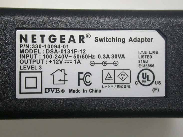
Click to zoom
Application Details
- Equipment Class
- DTS - Digital Transmission System
- Date of Grant
- Oct 16, 2005
- Application Purpose
- Original Equipment
- Date of Application
- Oct 16, 2005
- Equipment Note
- 11g 8 port wireless VPN router
- Frequency Range
- 2412.00000000 - 2462.00000000
- Company
- Netgear Incorporated
- Country
- United States
Documents & Files
Document Text
Text extracted from the exhibit documents filed with the FCC. Open a document above to read the original.
Users Manual
202-10015-01 202-10015-01 November 2003 NETGEAR, Inc. 4500 Great America Parkway Santa Clara, CA 95054 USA Reference Manual for the NETGEAR ProSafe VPN Client Regulatory Approvals FCC Statement This equipment has been tested and found to comply with the limits for a Class B digital device, pursuant to Part 15 of the FCC Rules. These limits are designed to provide reasonable protection against harmful interference in a residential installation. This equipment generates, uses and can radiate radio frequency energy and, if not installed and used in accordance with the instructions, may cause harmful interference to radio communica- tions. However, there is no guarantee that interference will not occur in a particular installation. If this equipment does cause harmful interference to radio or television reception, which can be determined by turning the equipment off and on, the user is encouraged to try to correct the interference by one of the following measures: Reorient or relocate the receiving antenna. Increase the separation between the equipment and receiver. Connect the equipment into an outlet on a circuit different from that to which the receiver is connected. Consult the dealer or an experienced radio/TV technician for help. To assure continued compliance, any changes or modifications not expressly approved by the party responsible for compliance could void the user's authority to operate this equipment. (Example - use only shielded interface cables when connecting to computer or peripheral devices). FCC Radiation Exposure Statement This equipment complies with FCC RF radiation exposure limits set forth for an uncontrolled environment. This equipment should be installed and operated with a minimum distance of 20 centimeters between the radiator and your body. This device complies with Part 15 of the FCC Rules. Operation is subject to the following two conditions: (1) This device may not cause harmful interference, and (2) This device must accept any interference received, including interference that may cause undesired operation. This transmitter must not be co-located or operating in conjunction with any other antenna or transmitter. The antennas used for this transmitter must be installed to provide a separation distance of at least 20 cm from all persons and must not be co-located or operating in conjunction with any other antenna or transmitter. Channel The Wireless Channel sets the radio frequency used for communication. Access Points use a fixed Channel. You can select the Channel used. This allows you to choose a Channel which provides the least interference and best performance. In the USA and Canada, 11 channel are available. If using multiple Access Points, it is better if adjacent Access Points use different Channels to reduce interference. In "Infrastructure" mode, Wireless Stations normally scan all Channels, looking for an Access Point. If more than one Access Point can be used, the one with the strongest signal is used. (This can only happen within an ESS.) If using "Ad-hoc" mode (no Access Point), all Wireless stations should be set to use the same Channel. However, most Wireless stations will still scan all Channels to see if there is an existing "Ad-hoc" group they can join. CAUTION: 1) To comply with FCC RF exposure compliance requirements, a separation distance of at least 20 cm must be maintained between the antenna of this device and all persons. 2) This transmitter must not be co-located or operating in conjunction with any other antenna or transmitter. ii 202-10015-01 © 2003 by NETGEAR, Inc. All rights reserved. Trademarks NETGEAR and Auto Uplink are trademarks or registered trademarks of Netgear, Inc. Microsoft, Windows, and Windows NT are registered trademarks of Microsoft Corporation. Other brand and product names are registered trademarks or trademarks of their respective holders. Statement of Conditions In the interest of improving internal design, operational function, and/or reliability, NETGEAR reserves the right to make changes to the products described in this document without notice. NETGEAR ™ does not assume any liability that may occur due to the use or application of the product(s) or circuit layout(s) described herein. Technical Support Refer to the Support Information Card that shipped with your NETGEAR ProSafe VPN Client. World Wide Web NETGEAR maintains a World Wide Web home page that you can access at the universal resource locator (URL) http://www.netgear.com. A direct connection to the Internet and a Web browser such as Internet Explorer or Netscape are required. Contentsiii 202-10015-01M-10207-01, Reference Manual v2 Contents Chapter 1 About This Manual Audience, Versions, Conventions ...................................................................................1-1 How to Use this Manual ..................................................................................................1-2 How to Print this Manual .................................................................................................1-3 Chapter 2 Introduction What's Included? ............................................................................................................2-1 What’s in the Box? ..........................................................................................................2-2 Chapter 3 Installation What You Need Before You Begin ..................................................................................3-1 System Requirements ..............................................................................................3-1 Installing .........................................................................................................................3-2 Upgrading .......................................................................................................................3-3 Getting Started ................................................................................................................3…
Text truncated - open the document above for the full version.
Cover Letter(s)
Federal Communications Commission Dear Sir, We, the undersigned, hereby authorize Exclusive Certification Corp. to act on our behalf in all matters relating to application for 11g 8 port wireless VPN router (Model: FVG318, FCC ID No.: PY305200007)” authorization, including the signing of all documents relating to these matters. Any and all carried out by Exclusive Certification Corp. on our behalf shall have the same effect as acts of our own. The applicant certifies that in the case of an individual applicant (e.g., corporation), no party to the applicant is subject to a denial of federal benefits, that includes FCC benefits, pursuant to section 5301 of the Anti-drug abuse Act of 1988.21 U.S.A. 862. For a definition of a “party” for these purposes See 47 C.F.R. 1.2002(b). By: By: Mark Gandler (Signature) (Printed) Title : Compliance Manager Applicant: Netgear Inc. Address: 4500 Great America Parkway, Santa Clara, California 95054 USA Tel: +1-408-907-8000 Fax: +1-408-907-8097 E-mail: [email protected] Date: July 20, 2005
Cover Letter(s)
CONFIDENTIAL LETTER July 07, 2005 Federal Communications Commission Authorization and Evaluation Division FCC ID:PY305200007 Confidentiality Request Pursuant to Sections 0.457 and 0.459 of the Commission’s Rules, the Applicant Hereby requests confidential treatment of information accompaniment this Application As outlined below: 1. Block Diagram, 2. Schematic Diagram, The above materials contain trade secrets and proprietary information not customarily released to the public. The public disclosure of these matters might be harmful to the Applicant and provide unjustified benefits to its competitors. The Applicant understands that pursuant to Rule 0.457, disclosure of this Application and all accompanying documentation will not be made before the date of the Grant for this application Sincerely, ____________________________ Mark Gandler/Compliance Manager Applicant: Netgear, Inc. Address: 4500 Great America Parkway, Santa Clara, California 95054 USA TEL: +1-408-907-8000 FAX: +1-408-907-8097
External Photos
External Photo 1 External Photo 2 External Photo 3 External Photo 4 External Photo 5 External Photo 6 External Photo 7 External Photo 8
ID Label/Location Info
SHEET: AUTHOR:TITLE: P/N: REV: THIS DOCUMENT AND THE DATA DISCLOSED HEREIN OR WHEREWITH IS NOT TO BE REPRODUCED, USED OR DISCLOSED IN WHOLE OR IN PART TO ANYONE WITHOUT THE PERMISSION OF NETGEAR, INC. REVDESCRIPTION OF REVISIONENG APPDDATE 01272-10252-021 of 1 PLBL, FVG318, V1H1M YU 04-14-05M YUINITIAL DOCUMENT CREATION01 Pantone Cool Gray 11C NOTE: 1. Label Size: 50*30mm 2. MAC & SERIAL NUMBERS TO BE PRINTED BY THE ODM. 3. DIE LINES ARE MAGENTA COLOR AND DO NOT PRINT. 4. INK COLOR IS SHOWN TO THE RIGHT. 5. INSURE COUNTRY OF ORIGIN IS CORRECT. A. IF COUNTRY OF ORIGIN IS PRE-PRINTED, UNHIDE THE APPROPRIATE COUNTRY OF ORIGIN LAYER AND INCLUDE COUNTRY OF ORIGIN ON LABEL. B. IF COUNTRY OF ORIGIN IS POST-PRINTED USING A THERMAL PRINTER (OR EQUIVALENT), UNHIDE THE WHITE BOX LAYER AND INCLUDE WHITE BOX ON LABEL. 5
Internal Photos
Internal Photo 1 Internal Photo 2 Internal Photo 3 Internal Photo 4 Internal Photo 5 Internal Photo 6 Internal Photo 7 Internal Photo 8 Internal Photo 9
Operational Description
FVG318 Product Operation Principle Instructions DUT: FVG318 A: Need three PCs, which are PC1,PC2,PC3. B: Use UL/AU/UK/EU12VDC@1A power adapters. C: Power on FVG318,link one of the Device’s LAN port to the PC1,which can get the IP address automatically when the device start to work; link WAN port of Device to another PC2,then input 192.168.0.1 in IE page, and you can enter FVG318 setup pages, click WAN setting to get IP of WAN port. EMI Test: 1.Put the device FVG318and PC3 in the EMI chamber,PC3 need have wireless card, so that it canbeused to link to the device’s WLAN port. 2.Put the PC1,PC2 out of the chamber, link the PC1 which can get IP Address automatically to the LAN port of FVG318 using one UTP cable, and link the PC2 to the WAN port of FVG318 device usinganotherUTP cable. Set the PC2 address:192.168.0.2, IP Subnet Mask:255.255.255.0,Gateway IP Address: 192.168. 0.1. 3.Power on FVG318,do the command”ping 192.168.0.2–t”at the PC1,it can get responses fromPC2;The PC3 in the chamber link to the WLAN port of FVG318 device, and you can run art.exe in art_v53_build5_all file getting from Atheros corporation tosetupwireless working mode, please run art\remote=192.168.0.20 to setup TX/RX/Link mode to test. Block Diagram: FVG318 Block Diagram as below: 1. CPU, U3, AR2316 Single Chip MAC/ Baseband/ Radio/ Processor for 2.4GHz Wireless LANs. The Atheros AR2316 integrated the MAC/ baseband/ radio and processor into a single chip for wireless access point and router applications. It includes a 2.4GHz radio, MIPS 4000 processor, 802.11 MAC/ baseband processor, 802.3 Ethernet MAC and MII interface, SDRAM controller, external memory interface for Flash, ROM, or UART, GPIOs, LED controls. The AR2316 implements an 802.11 MAC/ baseband processor supporting all IEEE 802.11g data rates (1 to 54 Mbps) and all IEEE 802.11b complementary key coding (CCK) data rates (1 to 11 Mbps). In Atheros super G TM mode, AR2316 supports data rates up to 108 Mbps. Additional features include forward error correction coding at rates for 1/2, 2/3, and 3/4, signal detection, automatic gain control, frequency offset estimation, symbol timing, channel estimation, error recovery, enhanced security, and quality of service (QoS).The AR2316 performs receive and transmit filtering for IEEE 802.3 and 802.11 network. 2. 2.4GHz – 2.5GHz Power Amplifier, U4, GP1214 GP1214 is a low cost and high performance power amplifier IC based on the highly reliable InGaP/GaAs HBT technology. With a 3x3 mm2 16-pin LCC package, GP1214 can be easily configured for high power/high efficiency application with superb power added efficiency while operating over the 2.4~2.5 GHz frequency band. It typically provides 30dB gain with 22% power added efficiency @ Pout= 22 dBm for 802.11g and 27% power added efficiency @ Pout= 24 dBm for 802.11b. GP1214 has excellent linearity, typically <4% added EVM up to 20 dBm output power which is essential for 54 Mbps 802.11g operation while meeting 802.11g spectrum mask at 23 dBm. GP1214 also has wide-range (>25dB) temperature stable (~1dB over 80°C) single-ended/differential power detectors which lower users’ cost on power control. The power amplifier IC also features easy board level usage along with high speed power up/down control. Ultra-low reference current (total Iref<4mA) makes GP1214 controllable by on/off switching signal directly from baseband chip. These features coupled with low operating current make GP1214 ideal for the final stage power amplification in battery powered 802.11g/b WLAN transmitter applications. PDF created with pdfFactory Pro trial version www.pdffactory.com 5 5 4 4 3 3 2 2 1 1 DD CC BB AA LPFANT(OPTIONAL) OPB : OUTPUT POWER BOOSTER BPF : BAND PASS FILTER PDET : POWER DETECTOR LPF : LOW PASS FILTER ANT : ANTENNA XLNA : EXTERNAL LOW NOISE AMPLIFIER LPF SWITCHER 1.8V Regulator 3.3V 1.8V Vin ETHERNET SWITCH PNP/LDO 1.5V LPFANT AR2316 PNP/LDO 3.3V 2.5V ETHERNET SWITCH POWER SDRAM P0P1P2P3P4 2.5V 1.5V MII_MDC MII_MDIO MII_CRS MII_COL MII_RXD[0:3] MII_TXD[0:3] MII_RXC MII_RXDV MII_TXC MII_TXEN 88E606088E6060 III control_15 control_25 MII_TXEN MII_MDIO MII_MDC MII_TXD[0:3] MII_RXC MII_RXDV MII_TXC MII_CRS MII_RXD[0:3] MII_COL control_25 control_15 PDET COUPLER FLASH 4M/8M16M/32M S D _ D A T A [ 0 : 1 5 ] S D _ A D D R [ 0 : 1 2 ] S D _ C L K S D _ R A S S D _ C A S S D _ D Q M [ 0 : 1 ] S D _ W E S D _ C S S D _ C K E S P I _ C K S P I _ M I S O S P I _ M O S I S P I _ C S BPFOPB XLNABPF SWITCH L A N * 8 WAN P4P2P3P0 P1 12V@1A W A N / L A N L E D * 1 8 LAN LED*10 WAN LED*2+LAN LED*6 P O W E R / S T A T U S / W L A N L E D * 3 GPIO GPIO GPIO LED RFOUT RFIN 3.3V 40MHz XTAL F W _ R S T ( G P I O ) RESET IC H W _ R S T 25MHz XTAL 25MHz XTAL 3.3V MAC/Baseband/Radio ProcessorControlUnit(U3) TheFVG318is a802.11b/g Wireless Broadband Router with8-ports Fast Ethernet Switch,With a web-based UI,itis easy to setup and maintain. Allfunctions can be configured with the exclusive, easy and friendly user interface via web browsers. The AR2316 integrated the MAC/baseband/radio and processor into a single chip for wireless access point and router applications. It includes a 2.4 GHz radio, MIPS 4000 processor,802.11 MAC/baseband processor,802.3 ethernet MAC and MII interface, The AR2316 implements an 802.11 MAC/baseband processor supporting all IEEE 802.11g data rate(1 to 54 Mbps) and all IEEE 802.11b complementary key coding (CCK) datarates(1 to 11 Mbps).In Super G mode,AR2316 supports data rates up to 108 Mbps. Additional features include forward error correction coding at rates for 1/2,2/3,and 3/4,signal detection, automatic gain control, frequency offset estimation, symbol timing, channel estimation, error recovery, enhanced security, and quality of service(QoS).The AR2316 performs receive and transmit filtering for 802.3/802.11. Fast Ethernet Switch with 10Base-T/100Base-TX(U1,U9) The Marvell 88E6060 is a single chip integration ofa complete 6-port Fast Ethernet switch with support for a CPU connection. It…
Text truncated - open the document above for the full version.
RF Exposure Info
1.1. Test Result of RF Exposure Evaluation . Product: 11g 8 port wireless VPN router . Test Item: RF Exposure Evaluation Data . Test site: OATSI-SD . Test Mode: Transmit / Receive 1.1.1. Antenna Gain The maximum Gain is 5.0 dBi. 1.1.2. EUT Operation condition Software provided by client enabled the EUT to transmit and receive data at lowest, middle and highest channel individually. 1.1.3. Output Power into Antenna & RF Exposure Evaluation Distance Modulation Standard: IEEE 802.11b Test Date: Aug. 23, 2005 Temperature: 25 Humidity: 70 Channel Channel Frequency (MHz) Output Power to Antenna (dBm) Power Density (S) (mW/cm 2 ) 01 2412 17.23 0.033 06 2437 17.77 0.038 11 2462 17.68 0.037 Modulation Standard: IEEE 802.11g Test Date: Aug. 23, 2005 Temperature: 25 Humidity: 70 Channel Channel Frequency (MHz) Output Power to Antenna (dBm) Power Density (S) (mW/cm 2 ) 01 2412 15.83 0.024 06 2437 15.94 0.025 11 2462 15.89 0.024 The MPE is calculated as 0.038 mW / cm 2 < limit 1 mW / cm 2 . So, RF exposure limit warning or SAR test are not required.
Test Report
Exclusive Certification Corp. Tel:886-2-2792-3366 Fax:886-2-2792-1100 Issued date: Sep. 16, 2005 1 of 112 FCC Test Report: FI05061402-A FCC TEST REPORT according to FCC Rules and Regulations Part 15 Subpart C Laboratory Accreditation 1332 The test result refers exclusively to the test presented test model / sample., Without written approval of Exclusive Certification Corp. the test report shall not be reproduced except in full. The EUT is also considered as a kind of computer peripheral, because the connection to computer is necessary for typical use. It has been verified to comply with the requirements of FCC Part 15, Subpart B, Class B (DoC). The test report has been issued separately. Applicant Netgear Inc. Address 4500 Great America Parkway Santa Clara California 95054 USA Equipment 11g 8 port wireless VPN router Model No. FVG318 FCC ID PY305200007 Trade Name Netgear Exclusive Certification Corp. Tel:886-2-2792-3366 Fax:886-2-2792-1100 Issued date: Sep. 16, 2005 2 of 112 FCC Test Report: FI05061402-A Contents 1. Report of Measurements and Examinations .................................................................................... 5 1.1 List of Measurements and Examinations ................................................................................... 5 2. Test Configuration of Equipment under Test ................................................................................... 6 2.1 Feature of Equipment under Test............................................................................................... 6 2.2 RF Module Specifications .......................................................................................................... 6 2.3 Test Mode and Test Software..................................................................................................... 7 2.4 Description of Test System......................................................................................................... 7 2.5 Connection Diagram of Test System..........................................................................................8 2.6 General Information of Test........................................................................................................ 9 2.7 History of this test report ............................................................................................................ 9 3. Antenna Requirements.....................................................................................................................10 3.1 Standard Applicable .................................................................................................................10 3.2 Antenna Construction and Directional Gain............................................................................. 10 4. Test of Conducted Emission............................................................................................................ 11 4.1 Test Limit.................................................................................................................................. 11 4.2 Test Procedures....................................................................................................................... 11 4.3 Typical Test Setup ...................................................................................................................12 4.4 Measurement equipment .........................................................................................................12 4.5 Test Result and Data................................................................................................................13 5. Test of Radiated Emission ...............................................................................................................33 5.1 Test Limit..................................................................................................................................33 5.2 Test Procedures.......................................................................................................................33 5.3 Typical Test Setup ....................................................................................................................33 5.4 Measurement equipment .........................................................................................................33 5.5 Test Result and Data................................................................................................................33 6. 6dB Bandwidth Measurement Data .................................................................................................33 6.1 Test Limit ..................................................................................................................................33 6.2 Test Procedures .......................................................................................................................33 6.3 Test Setup Layout .......................................................................................................... ..........33 6.4 Measurement equipment .........................................................................................................33 6.5 Test Result and Data................................................................................................................33 7. Maximum Peak Output Power .........................................................................................................33 7.1 Test Limit ..................................................................................................................................33 7.2 Test Procedures .......................................................................................................................33 7.3 Test Setup Layout ....................................................................................................................33 7.4 List of Measuring Equipment Used .............................................................................…
Text truncated - open the document above for the full version.
Test Setup Photos
Test Setup Photo 1 Test Setup Photo 2 Test Setup Photo 3 Test Setup Photo 4
Contact Information
Applicant
David Kay
Technical Contact
Netgear Inc.Mark Gandler
0014089078000
4500 Great America Parkway · Santa Clara, California · United States
Test Firm
Cerpass Technology CorporationAnson Chou
Technical Specifications
| # | Rule Parts | Frequency Range | Power Output |
|---|---|---|---|
| 1 | 15C | 2.41 GHz - 2.46 GHz | 60.00 mW |
Other Applications from Netgear Incorporated

PY325100647
Aug 04, 2026BE5000 Dual-Band PoE 2.5G Insight Managed WiFi 7 Outdoor Access Point
Equipment Class
DTS - Digital Transmission SystemPY325300652
May 12, 2026BE5000 Dual-Band PoE 2.5G Insight Managed WiFi 7 Access Point
Equipment Class
NII - Unlicensed National Information Infrastructure TXPY325400656
Apr 16, 2026Orbi Outdoor Satellite
Equipment Class
DTS - Digital Transmission SystemPY324400640
Dec 12, 2025Orbi 11BE WiFi 7 Tri-band Router, Orbi 11BE WiFi 7 Tri-band Satellite
Equipment Class
NII - Unlicensed National Information Infrastructure TXPY324100618
Jul 31, 2024Nighthawk 5G Mobile Router
Equipment Class
PCB - PCS Licensed Transmitter