PY305200015ProSafe Dual Band Wireless Access Point
Netgear Incorporated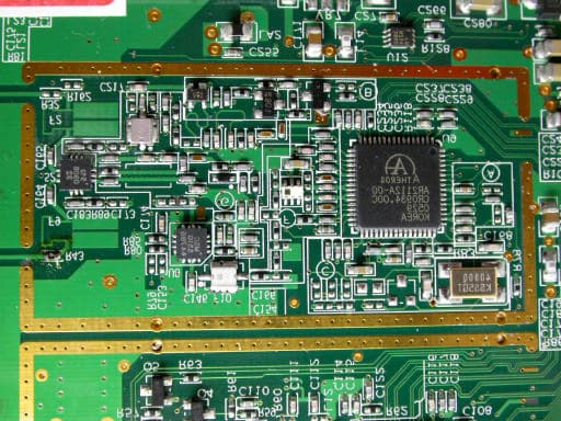
Click to zoom
Application Details
- Equipment Class
- NII - Unlicensed National Information Infrastructure TX
- Date of Grant
- Dec 05, 2005
- Application Purpose
- Original Equipment
- Date of Application
- Dec 05, 2005
- Equipment Note
- ProSafe Dual Band Wireless Access Point
- Frequency Range
- 5250.00000000 - 5350.00000000
- Company
- Netgear Incorporated
- Country
- United States
Documents & Files
Document Text
Text extracted from the exhibit documents filed with the FCC. Open a document above to read the original.
Users Manual
202-10062-03 September 2005 NETGEAR, Inc. 4500 Great America Parkway Santa Clara, CA 95054 USA Reference Manual for the NETGEAR ProSafe Dual Band Wireless Access Point WAG102 Regulatory Approvals FCC Statement This equipment has been tested and found to comply with the limits for a Class B digital device, pursuant to Part 15 of the FCC Rules. These limits are designed to provide reasonable protection against harmful interference in a residential installation. This equipment generates, uses and can radiate radio frequency energy and, if not installed and used in accordance with the instructions, may cause harmful interference to radio communica- tions. However, there is no guarantee that interference will not occur in a particular installation. If this equipment does cause harmful interference to radio or television reception, which can be determined by turning the equipment off and on, the user is encouraged to try to correct the interference by one of the following measures: Reorient or relocate the receiving antenna. Increase the separation between the equipment and receiver. Connect the equipment into an outlet on a circuit different from that to which the receiver is connected. Consult the dealer or an experienced radio/TV technician for help. To assure continued compliance, any changes or modifications not expressly approved by the party responsible for compliance could void the user's authority to operate this equipment. (Example - use only shielded interface cables when connecting to computer or peripheral devices). FCC Radiation Exposure Statement This equipment complies with FCC RF radiation exposure limits set forth for an uncontrolled environment. This equipment should be installed and operated with a minimum distance of 20 centimeters between the radiator and your body. This device complies with Part 15 of the FCC Rules. Operation is subject to the following two conditions: (1) This device may not cause harmful interference, and (2) This device must accept any interference received, including interference that may cause undesired operation. This transmitter must not be co-located or operating in conjunction with any other antenna or transmitter. The antennas used for this transmitter must be installed to provide a separation distance of at least 20 cm from all persons and must not be co-located or operating in conjunction with any other antenna or transmitter. Channel The Wireless Channel sets the radio frequency used for communication. Access Points use a fixed Channel. You can select the Channel used. This allows you to choose a Channel which provides the least interference and best performance. In the USA and Canada, 11 channel are available. If using multiple Access Points, it is better if adjacent Access Points use different Channels to reduce interference. In "Infrastructure" mode, Wireless Stations normally scan all Channels, looking for an Access Point. If more than one Access Point can be used, the one with the strongest signal is used. (This can only happen within an ESS.) If using "Ad-hoc" mode (no Access Point), all Wireless stations should be set to use the same Channel. However, most Wireless stations will still scan all Channels to see if there is an existing "Ad-hoc" group they can join. CAUTION: 1) To comply with FCC RF exposure compliance requirements, a separation distance of at least 20 cm must be maintained between the antenna of this device and all persons. 2) This transmitter must not be co-located or operating in conjunction with any other antenna or transmitter. ii v1.0, September 2005 Technical Support Please register to obtain technical support. Please retain your proof of purchase and warranty information. To register your product, get product support or obtain product information and product documentation, go to http://www.NETGEAR.com . If you do not have access to the World Wide Web, you may register your product by filling out the registration card and mailing it to NETGEAR customer service. You will find technical support information at: http://www.NETGEAR.com/ through the customer service area. If you want to contact technical support by telephone, see the support information card for the correct telephone number for your country. © 2005 by NETGEAR, Inc. All rights reserved. Trademarks NETGEAR is a registered trademark of NETGEAR, INC. Windows is a registered trademark of Microsoft Corporation. Other brand and product names are trademarks or registered trademarks of their respective holders. Information is subject to change without notice. All rights reserved. Statement of Conditions In the interest of improving internal design, operational function, and/or reliability, NETGEAR reserves the right to make changes to the products described in this document without notice. NETGEAR does not assume any liability that may occur due to the use or application of the product(s) or circuit layout(s) described herein. Modifications made to the product, unless expressly approved by Netgear, could void the user’s authority to operate the equipment. NETGEAR does not assume any liability that may occur due to such condition. v1.0, September 2005 iii Federal Communications Commission (FCC) Compliance Notice: Radio Frequency Notice This device complies with part 15 of the FCC Rules. Operation is subject to the following two conditions: 1.This device may not cause harmful interference. 2.This device must accept any interference received, including interference that may cause undesired operation. Placement and Range Guidelines Indoors, computers can connect over 802.11 wireless networks at a maximum range of 500 feet (152.4 m) for 802.11b devices. However, the operating distance or range of your wireless connection can vary significantly, based on the physical placement of the wireless access point. For best results, identify a location for your wireless access point according to these guidelines: •Away from potential sources of interference, such as PCs, large …
Text truncated - open the document above for the full version.
Cover Letter(s)
Request for non-disclosure RF_501_02 Netgear Inc. 4500 Great America Parkway Santa Clara California 95054 USA To: Telefication B.V. Attn: Dept. FCC TCB Edisonstraat 12A 6902 PK ZEVENAAR The Netherlands Subject: Request for non-disclosure (FCC ID:PY305200015) Reference number: WAG102 Date: 2005-11-10 Dear FCC TCB, Persuant to 47 CFR Section 0.459(a) & (b), <Netgear Inc. > hereby requests non-disclosure and confidential treatment of the following materials submitted in support of FCC certification application for FCC ID: PY305200015 a. Schematic diagrams b. Block Digram Above materials contain secrets, proprietary and technical information, which would customarily be quarded from competitors under 47 CFR, section 0.457(d)(2). Disclosure or publication or any portion of this company confidential material to other parties could cause substantial competitive harm and provide unjustified benefits for competitors. <Netgear Inc. > understands that pursuant to 47 CFR section 0.457(d)(1)(ii) disclosure of the applicant and all accompanying documentation will not be made before the date of the grant. Netgear Inc. Mark Gandler
Cover Letter(s)
RF_160, Issue 01 Declaration of Authorization We Name: Netgear Inc. Address: 4500 Great America Parkway Santa Clara City: California 95054 Country: USA Declare that: Name: Exclusive Certification Corporation. Address: 4F-2, No. 28, Lane 78, Nei-hu City: Taipei City 114 Country: Taiwan, R. O. C. is authorized to apply for Certification of the following product(s): Product description: ProSafe Dual Band Wireless Access Point Type designation: WAG102 Trademark: NETGEAR on our behalf. Date: 2005/11/10 City: Taipei City Name: Mark Gandler Signature:
External Photos
Exclusive Certification Corp. Tel:886-2-2792-3366 Fax:886-2-2792-1100 Issued date: Nov. 02, 2005 1 of 8 FCC Test Report: FI05080301-A Appendix A. Photographs of EUT 05080301-A 05080301-A Exclusive Certification Corp. Tel:886-2-2792-3366 Fax:886-2-2792-1100 Issued date: Nov. 02, 2005 2 of 8 FCC Test Report: FI05080301-A 05080301-A Exclusive Certification Corp. Tel:886-2-2792-3366 Fax:886-2-2792-1100 Issued date: Nov. 02, 2005 3 of 8 FCC Test Report: FI05080301-A 05080301-A 05080301-A Exclusive Certification Corp. Tel:886-2-2792-3366 Fax:886-2-2792-1100 Issued date: Nov. 02, 2005 4 of 8 FCC Test Report: FI05080301-A 2.4GHz of RF part 5GHz of RF part 05080301-A 05080301-A Exclusive Certification Corp. Tel:886-2-2792-3366 Fax:886-2-2792-1100 Issued date: Nov. 02, 2005 5 of 8 FCC Test Report: FI05080301-A Dipole antenna (Antenna gain 5dBi) Ceiling antenna (Antenna gain 5dBi- ANT2405) 05080301-A 05080301-A Exclusive Certification Corp. Tel:886-2-2792-3366 Fax:886-2-2792-1100 Issued date: Nov. 02, 2005 6 of 8 FCC Test Report: FI05080301-A GP Omni-directional antenna (Antenna gain 9dBi- ANT2409) Patch antenna (Antenna gain 18dBi- ANT24D18) 05080301-A 05080301-A Exclusive Certification Corp. Tel:886-2-2792-3366 Fax:886-2-2792-1100 Issued date: Nov. 02, 2005 7 of 8 FCC Test Report: FI05080301-A DSA-0131F-12 05080301-A 05080301-A Exclusive Certification Corp. Tel:886-2-2792-3366 Fax:886-2-2792-1100 Issued date: Nov. 02, 2005 8 of 8 FCC Test Report: FI05080301-A 05080301-A 05080301-A
ID Label/Location Info
SHEET: AUTHOR:TITLE: P/N: REV: THIS DOCUMENT AND THE DATA DISCLOSED HEREIN OR WHEREWITH IS NOT TO BE REPRODUCED, USED OR DISCLOSED IN WHOLE OR IN PART TO ANYONE WITHOUT THE PERMISSION OF NETGEAR, INC. REVDESCRIPTION OF REVISIONENG APPDDATE 01272-10281-021 of 1 PLBL, WAG102, V1H1M YU 10/24/05M YUINITIAL DOCUMENT CREATION01 NOTE : 1. REFER TO NETGEAR SPEC. 270-10101-01 FOR MATERIAL SPECIFICATIONS AND TOLERANCES. 2. MAC & SERIAL NUMBERS TO BE PRINTED BY THE ODM. 3. DIE LINES ARE MAGENTA COLOR AND DO NOT PRINT. 4. INK COLOR IS SHOWN TO THE RIGHT. 5. INSURE COUNTRY OF ORIGIN IS CORRECT. A. IF COUNTRY OF ORIGIN IS PRE-PRINTED, UNHIDE THE APPROPRIATE COUNTRY OF ORIGIN LAYER AND INCLUDE COUNTRY OF ORIGIN ON LABEL. B. IF COUNTRY OF ORIGIN IS POST-PRINTED USING A THERMAL PRINTER (OR EQUIVALENT), UNHIDE THE WHITE BOX LAYER AND INCLUDE WHITE BOX ON LABEL. 5 Pantone Cool Gray 11C This device complies with Part 15 of the FCC Rules. Operation is subject to the following two conditions: (1) This device may not cause harmful interference, and (2) This device must accept any interference received, including interference that may cause undesired operation.
Internal Photos
Exclusive Certification Corp. Tel:886-2-2792-3366 Fax:886-2-2792-1100 Issued date: Nov. 02, 2005 1 of 8 FCC Test Report: FI05080301-A Appendix A. Photographs of EUT 05080301-A 05080301-A Exclusive Certification Corp. Tel:886-2-2792-3366 Fax:886-2-2792-1100 Issued date: Nov. 02, 2005 2 of 8 FCC Test Report: FI05080301-A 05080301-A Exclusive Certification Corp. Tel:886-2-2792-3366 Fax:886-2-2792-1100 Issued date: Nov. 02, 2005 3 of 8 FCC Test Report: FI05080301-A 05080301-A 05080301-A Exclusive Certification Corp. Tel:886-2-2792-3366 Fax:886-2-2792-1100 Issued date: Nov. 02, 2005 4 of 8 FCC Test Report: FI05080301-A 2.4GHz of RF part 5GHz of RF part 05080301-A 05080301-A Exclusive Certification Corp. Tel:886-2-2792-3366 Fax:886-2-2792-1100 Issued date: Nov. 02, 2005 5 of 8 FCC Test Report: FI05080301-A Dipole antenna (Antenna gain 5dBi) Ceiling antenna (Antenna gain 5dBi- ANT2405) 05080301-A 05080301-A Exclusive Certification Corp. Tel:886-2-2792-3366 Fax:886-2-2792-1100 Issued date: Nov. 02, 2005 6 of 8 FCC Test Report: FI05080301-A GP Omni-directional antenna (Antenna gain 9dBi- ANT2409) Patch antenna (Antenna gain 18dBi- ANT24D18) 05080301-A 05080301-A Exclusive Certification Corp. Tel:886-2-2792-3366 Fax:886-2-2792-1100 Issued date: Nov. 02, 2005 7 of 8 FCC Test Report: FI05080301-A DSA-0131F-12 05080301-A 05080301-A Exclusive Certification Corp. Tel:886-2-2792-3366 Fax:886-2-2792-1100 Issued date: Nov. 02, 2005 8 of 8 FCC Test Report: FI05080301-A 05080301-A 05080301-A
Operational Description
WAG102 Operation Principle 1. CPU, U10, The Atheros AR5312 is part of the three-chip AR5002AP solution for dual,concurrent IEEE 802.11a/b/g 2.4/5GHz WLAN AP applications. The AR5312 supports 802.11 a/b/g MAC/Baseband processing; two 802.3 MAC and MII interfaces to external Ethernet PHY; SDRAM Controller; external memory interface for Flash, ROM or RAM; GPIO; LED controls; a high speed UART with DMA supporting data rates up to 1 Mbps for serial port applications; and a flexible local bus. 2. FLASH, U11, AM29LV160DB-90, 16Mbits Flash, Bottom sector, and 90ns. It is used to store the normal and test firmware. 3. 2.4GHz Transceiver, U9, The AR2112 operates in the 2.4GHz frequency bands. The transmitter combines baseband in-phase(I) and quadrature-phase(Q) signals, up-converts them to the desired frequency channel, and drives the RF signal off-chip through the integrated power amplifier. The receiver uses an integrated dual conversion architecture and requires no off-chip intermediate frequency(IF) filter. 4. 2.4/5GHz Transceiver, U3,The AR5112 can operate in either the 2.4GHz frequency band or the 5GHz band. The transmitter combines baseband in-phase(I) and quadrature-phase(Q) signals, up-converts them to the desired frequency channel, and drives the RF signal off-chip through the integrated power amplifier. The receiver uses an integrated dual conversion architecture and requires no off-chip intermediate frequency(IF) filter. 5. 2.4GHz~2.5GHz Power Amplifier, U8, The LX5510 is a power amplifier optimized for WLAN applications in the 2.4GHz-2.5GHz frequency range. The PA is implemented as at two-stage monolithic microwave integrated circuit (MMIC) with active bias and input/output pre-matching. 6. 4.5GHz~6GHz Power Amplifier, U2, The LX5506 is a power amplifier designed for the FCC Unlicensed National Information Infrastructure (U-NII) band, HyperLAN2 and Japan WLAN applications in the 4.9~5.95GHz frequency range. The PA is implemented as a three-stage monolithic microwave integrated circuit (MMIC) with active bias and complete on-chip input matching. 7. 10/100 Ethernet PHY, U5, RTL8201CP is a single-chip/single port PHYceiver with MII/SNI. It implements all 10/100M Ethernet Physical-layer functions including the Physical Coding Sublayer (PCS), Physical Medium Attachment (PMA), Twisted Pair Physical Medium Dependent Sublayer (TP-PMD), with an auto crossover detection function, 10Base-TX Encoder/Decoder, and Twisted Pair Media Access Unit (TPMAU). 8. Power part: there are 6 regulators used on the board. U102, TPS40060 is used to transfer DC24V to DC4.5V ;VR2&VR5, AME8805DEFT is used to transfer DC4.5V to DC2.5V ;VR1&VR3, AME8805AEGT is used to transfer DC 4.5V to DC3.3V; VR6, AME8807 is used to transfer DC2.5V to DC1.3V. The core of CPU is operate at 1.3V. 9. LED part: LED Color Description Power Green On - power on Off - no power Status Yellow On - Error condition. Off - Normal operation Blinking - This LED blinks during start up. LAN Green On – Link Blinking - Data is transmitted or received via Ethernet Off –No Link WLAN 2.4G Green On - Wireless connection available; Wireless Access Point is ready for use. Off - No Wireless connection available. Blinking - Data is transmitted or received via the Wireless access point. WLAN 5G Green On - Wireless connection available; Wireless Access Point is ready for use. Off - No Wireless connection available. Blinking - Data is transmitted or received via the Wireless access point. 10. Switch button, SW1, it is used to reset the AR5312. 11. 12. 13. 14.
RF Exposure Info
Test Result of RF Exposure Evaluation for FCC Part 15 Subpart C 15. 407 . Product: ProSafe Dual Band Wireless Access Point . Test Item: RF Exposure Evaluation Data . Test site: OATSI-SD . Test Mode: Transmit / Receive . Test Date: Oct. 25, 2005 . Temperature: 25 . Humidity: 68 1. Antenna Gain Antenna 1: The maximum Gain is 5.0 dBi.(Dipole antenna) 2. EUT Operation condition Software provided by client enabled the EUT to transmit and receive data at lowest, middle and highest channel individually. 3. Output Power into Antenna & RF Exposure Evaluation Distance (1) Antenna 1, Frequency Range: 5.15~5.35 GHz Modulation Standard: IEEE 802.11g (54 Mbps) Channel Channel Frequency (MHz) Output Power to Antenna (dBm) Power Density (S) (mW/cm 2 ) 01 5180 13.99 0.0160 04 5240 13.11 0.0130 05 5260 13.81 0.0150 08 5320 13.85 0.0150 4. The MPE is calculated as 0.016 mW / cm 2 < limit 1 mW / cm 2 . So, RF exposure limit warning or SAR test are not required.
Test Report
Exclusive Certification Corp. Tel:886-2-2792-3366 Fax:886-2-2792-1100 Issued date: Nov. 02, 2005 1 of 56 FCC Test Report: FE05080301-A FCC TEST REPORT according to FCC Rules and Regulations Part 15 Subpart E Laboratory accreditation 1332 † The test result refers exclusively to the test presented test model / sample., † Without written approval of Exclusive Certification Corp. the test report shall not be reproduced except in full. † The EUT is also considered as a kind of computer peripheral, because the connection to computer is necessary for typical use. It has been verified to comply with the requirements of FCC Part 15, Subpart B, Class B (DoC). The test report has been issued separately. Applicant Netgear Inc. Address 4500 Great America Parkway Santa Clara California 95054 USA Equipment ProSafe Dual Band Wireless Access Point Model No. WAG102 FCC ID PY305200015 Trade Name Netgear Exclusive Certification Corp. Tel:886-2-2792-3366 Fax:886-2-2792-1100 Issued date: Nov. 02, 2005 2 of 56 FCC Test Report: FE05080301-A CONTENTS 1. Report of Measurements and Examinations.................................................................................5 1.1. List of Measurements and Examinations............................................................................5 2. Test Configuration of Equipment under Test.................................................................................6 2.1. Feature of Equipment under Test.......................................................................................6 2.2. RF Specifications..............................................................................................................7 2.3. Test Mode and Test Software............................................................................................8 2.4. Description of Test System................................................................................................8 2.5. Connection Diagram of Test System..................................................................................9 3. General Information of Test........................................................................................................10 3.1. History of this test report..................................................................................................10 4. Antenna Requirements..............................................................................................................11 4.1. Standard Applicable.........................................................................................................11 4.2. Antenna Construction and Directional Gain.......................................................................11 5. Test of Conducted Emission.......................................................................................................12 5.1. Test Procedures..............................................................................................................12 5.2. Typical Test Setup Layout of Conducted Emission.............................................................13 5.3. Conducted Emission Requirement....................................................................................13 5.4. Test Result and Data.......................................................................................................14 6. Test of Radiated Emission..........................................................................................................23 6.1. Test Procedures..............................................................................................................23 6.2. Typical Test Setup Layout of Radiated Emission................................................................23 6.3. Test Result of Radiated Emission.....................................................................................24 7. Peak Transmit Power.................................................................................................................36 7.1. Test Procedure................................................................................................................36 7.2. Test Setup Layout............................................................................................................36 7.3. Test Result and Data.......................................................................................................36 8. Peak Power Excursion...............................................................................................................41 8.1. Test Procedure................................................................................................................41 8.2. Test Setup Layout............................................................................................................41 8.3. Test Result and Data.......................................................................................................41 9. Peak Power Spectral Density.....................................................................................................44 9.1. Test Procedure................................................................................................................44 9.2. Test Setup Layout............................................................................................................44 9.3. Test Result and Data.......................................................................................................44 10. Frequency Stability....................................................................................................................47 10.1. Test Procedure................................................................................................................47 10.2. Test Setup Layout............................................................................................................47 10.3. Test Result and Data.....................................................................................................…
Text truncated - open the document above for the full version.
Test Report
Exclusive Certification Corp. Tel:886-2-2792-3366 Fax:886-2-2792-1100 Issued date: Nov. 02, 2005 31 of 56 FCC Test Report: FE05080301-A Emission frequencies 1~40 GHz Test Mode: Normal, Channel 04, Transmit Rate:54Mbps Test Date: Oct. 20, 2005 Temperature: 22 Humidity: 70% Atmospheric pressure: 1020mmHg Frequency (MHz) Ant-Pol H/V Meter Reading (dBuV) Corrected Factor (dB) Result@3m (dBuV/m) Limit@3m (dBuV/m) Margin (dB) Remark Table Deg. Ant High (m) 10481.13 H 42.50 16.08 58.58 68.3 -9.72 Peak 246 1.0 15720.00 H --- 16.70 --- 54.0 --- Ave --- --- 20960.00 H --- 28.67 --- 54.0 --- Ave --- --- 26200.00 H --- 32.07 --- 68.3 --- Peak -- -- 10481.17 V 44.98 15.28 60.26 68.3 -8.04 Peak 350 1.0 15720.00 V --- 16.04 --- 54.0 --- Ave --- --- 20960.00 V --- 28.67 --- 54.0 --- Ave --- --- 26200.00 V --- 32.07 --- 68.3 --- Peak --- -- Notes: 1. Result = Meter Reading + Corrected Factor 2. Corrected Factor = Antenna Factor + Cable Loss – Amplifier 3. The resolution bandwidth of test receiver/spectrum analyzer is 120 kHz and video bandwidth is 300 kHz for Peak detection and Quasi-peak detection at frequency below 1GHz. 4. The resolution bandwidth of test receiver/spectrum analyzer is 1 MHz and video bandwidth is 3 MHz for Peak detection at frequency above 1GHz. 5. The resolution bandwidth of test receiver/spectrum analyzer is 1MHz and video bandwidth is 10Hz for Average detection at frequency above 1GHz. 6. The other emissions is too below to be measured. Exclusive Certification Corp. Tel:886-2-2792-3366 Fax:886-2-2792-1100 Issued date: Nov. 02, 2005 32 of 56 FCC Test Report: FE05080301-A Emission frequencies 1~40 GHz Test Mode: Normal, Channel 05, Transmit Rate: 54Mbps Test Date: Oct. 20, 2005 Temperature: 22 Humidity: 70% Atmospheric pressure: 1020mmHg Frequency (MHz) Ant-Pol H/V Meter Reading (dBuV) Corrected Factor (dB) Result@3m (dBuV/m) Limit@3m (dBuV/m) Margin (dB) Remark Table Deg. Ant High (m) 10521.25 H 42.38 16.13 58.51 68.3 -9.79 Peak 246 1.0 15780.00 H --- 16.55 --- 54.0 --- Ave --- --- 21040.00 H --- 28.90 --- 54.0 --- Ave --- --- 26300.00 H --- 32.23 --- 68.3 --- Peak -- -- 10521.10 V 44.15 15.33 59.48 68.3 -8.82 Peak 350 1.0 15780.00 V --- 15.91 --- 54.0 --- Ave --- --- 21040.00 V --- 28.90 --- 54.0 --- Ave --- --- 26300.00 V --- 32.23 --- 68.3 --- Peak --- -- Notes: 1. Result = Meter Reading + Corrected Factor 2. Corrected Factor = Antenna Factor + Cable Loss – Amplifier 3. The resolution bandwidth of test receiver/spectrum analyzer is 120 kHz and video bandwidth is 300 kHz for Peak detection and Quasi-peak detection at frequency below 1GHz. 4. The resolution bandwidth of test receiver/spectrum analyzer is 1 MHz and video bandwidth is 3 MHz for Peak detection at frequency above 1GHz. 5. The resolution bandwidth of test receiver/spectrum analyzer is 1MHz and video bandwidth is 10Hz for Average detection at frequency above 1GHz. 6. The other emissions is too below to be measured. Exclusive Certification Corp. Tel:886-2-2792-3366 Fax:886-2-2792-1100 Issued date: Nov. 02, 2005 33 of 56 FCC Test Report: FE05080301-A Emission frequencies 1~40 GHz Test Mode: Normal, Channel 08, Transmit Rate: 54Mbps Test Date: Oct. 20, 2005 Temperature: 22 Humidity: 70% Atmospheric pressure: 1020mmHg Frequency (MHz) Ant-Pol H/V Meter Reading (dBuV) Corrected Factor (dB) Result@3m (dBuV/m) Limit@3m (dBuV/m) Margin (dB) Remark Table Deg. Ant High (m) 10641.63 H 41.98 16.16 58.14 74.0 -15.86 Peak 246 1.0 15960.00 H --- 16.12 --- 54.0 --- Ave --- --- 21280.00 H --- 29.75 --- 54.0 --- Ave --- --- 26600.00. H --- 32.52 --- 68.3 --- Peak -- -- 10641.63 V 43.11 15.36 58.47 74.0 -15.53 Peak 350 1.0 15960.00 V --- 15.51 --- 54.0 --- Ave --- --- 21280.00 V --- 29.75 --- 54.0 --- Ave --- --- 26600.00 V --- 32.52 --- 68.3 --- Peak --- -- Notes: 1. Result = Meter Reading + Corrected Factor 2. Corrected Factor = Antenna Factor + Cable Loss – Amplifier 3. The resolution bandwidth of test receiver/spectrum analyzer is 120 kHz and video bandwidth is 300 kHz for Peak detection and Quasi-peak detection at frequency below 1GHz. 4. The resolution bandwidth of test receiver/spectrum analyzer is 1 MHz and video bandwidth is 3 MHz for Peak detection at frequency above 1GHz. 5. The resolution bandwidth of test receiver/spectrum analyzer is 1MHz and video bandwidth is 10Hz for Average detection at frequency above 1GHz. 6. The other emissions is too below to be measured. Exclusive Certification Corp. Tel:886-2-2792-3366 Fax:886-2-2792-1100 Issued date: Nov. 02, 2005 34 of 56 FCC Test Report: FE05080301-A 6.3.1. Photographs of Radiated Emission Test Test Model 1 Front View Rear View Exclusive Certification Corp. Tel:886-2-2792-3366 Fax:886-2-2792-1100 Issued date: Nov. 02, 2005 35 of 56 FCC Test Report: FE05080301-A Test Model 2 Front View Rear View Exclusive Certification Corp. Tel:886-2-2792-3366 Fax:886-2-2792-1100 Issued date: Nov. 02, 2005 36 of 56 FCC Test Report: FE05080301-A 7. Peak Transmit Power 7.1. Test Procedure The antenna port (RF output) of the EUT was connected to the input (RF input) of a spectrum analyzer. Power was read directly from the spectrum analyzer and cable loss connection was added to the reading to obtain power at the EUT antenna terminal. The EUT Output Power was set to maximum to produce the worse case test result. 7.2. Test Setup Layout 7.3. Test Result and Data (1) Test Mode: Normal, Transmit Rate: 54Mbps Test Date: Oct. 20, 2005 Temperature: 25 Humidity: 64% Atmospheric pressure: 1023mmHg Channel Frequency (MHz) Peak Power Output (dBm) Peak Power Output (mW) 26dB Occupied Bandwidth (MHz) 1 5180 13.99 25.061 23.80 4 5240 13.11 20.464 23.90 5 5260 13.81 24.044 24.20 8 5320 13.85 24.266 24.20 EUT Spectrum Analyzer Exclusive Certification Corp. Tel:886-2-2792-3366 Fax:886-2-2792-1100 Issued date: Nov. 02, 2005 37 of 56 FCC Test Report: FE05080301-A Peak Transmit Power Exclusive Certification Corp. Tel:886-2-2792-3366 Fax:886-2-2792-1100 Issued date: Nov. 02, 2005 38 of 56 FCC Test Report: FE05080301-A Exc…
Text truncated - open the document above for the full version.
Test Setup Photos
Test Setup Photos conduction Radiation Mode 1 Antanna 1 Antenna 2 Antenna 3 Antenna 4 Mode 2 Antenna 1 Antenna 2 Antenna 3 Antenna 4
Contact Information
Applicant
David Kay
Technical Contact
Netgear Inc.Mark Gandler
[email protected]+1 408 907 8000
4500 Great America Parkway · Santa Clara, California · United States
Test Firm
Cerpass Technology CorporationAnson Chou
Technical Specifications
| # | Rule Parts | Frequency Range | Power Output |
|---|---|---|---|
| 2 | 15E | 5.25 GHz - 5.35 GHz | 24.00 mW |
Other Applications from Netgear Incorporated

PY325100647
Aug 04, 2026BE5000 Dual-Band PoE 2.5G Insight Managed WiFi 7 Outdoor Access Point
Equipment Class
DTS - Digital Transmission SystemPY325300652
May 12, 2026BE5000 Dual-Band PoE 2.5G Insight Managed WiFi 7 Access Point
Equipment Class
NII - Unlicensed National Information Infrastructure TXPY325400656
Apr 16, 2026Orbi Outdoor Satellite
Equipment Class
DTS - Digital Transmission SystemPY324400640
Dec 12, 2025Orbi 11BE WiFi 7 Tri-band Router, Orbi 11BE WiFi 7 Tri-band Satellite
Equipment Class
NII - Unlicensed National Information Infrastructure TXPY324100618
Jul 31, 2024Nighthawk 5G Mobile Router
Equipment Class
PCB - PCS Licensed Transmitter