PY30530002354 Mbps ADSL Modem Wireless Router
Netgear Incorporated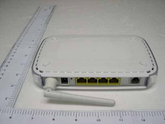
Click to zoom
Application Details
- Equipment Class
- DTS - Digital Transmission System
- Date of Grant
- Mar 20, 2006
- Application Purpose
- Original Equipment
- Date of Application
- Mar 20, 2006
- Equipment Note
- 54 Mbps ADSL Modem Wireless Router
- Frequency Range
- 2412.00000000 - 2462.00000000
- Company
- Netgear Incorporated
- Country
- United States
Documents & Files
Document Text
Text extracted from the exhibit documents filed with the FCC. Open a document above to read the original.
Users Manual
202-10155-01 Jan uary 2006 NETGEAR, Inc. 4500 Great America Parkway Sa nta Clara, CA 95054 USA Reference Manual for the 54 Mbps ADSL Modem Wireless Router Model DG834G ii v1.0, January 2006 © 2006 by NETGEAR, Inc. All rights reserved. Trademar ks NETGEAR is a trademark of Netg ear, Inc . Microsoft, Windows, and Windows NT are registered trademarks of Microsoft Corporation. Other brand and product names are registered trademarks or trademarks of their respective holders. Statem ent of Conditions In the interest of improving internal design, operational function, and/or reliabili ty, NETG EAR reserv es th e righ t to make changes to the products described in this docume nt wit hout notice . NETGEAR does not assume any liability that may occur due to the use or application of the product(s) or circuit layout(s) described herein. Fede ral Communications Commi ssion (FCC ) Compliance Notic e: Radio Fr eque ncy No tice This equipment has been tested and found to comply with the limits for a Class B digital device, pursuant to part 15 of the FCC Rules. These limits are de signed to provide reasonable protection against harmful interference in a reside nti al inst all ation. This equip men t generates, uses, and can radiate radio frequency energy and, if not installed and used in accordan ce with th e instruc tions, may cause harmful interference to radio communications. However, there is no guarantee that interference will not occur in a particular insta llati on. If this equipment does cause harmful interference to radio or television reception, which can be determined by turning the equipment off and on, the user is encouraged to try to correct the interference by one or more of the following measures: • Reorient or relocate the receiving antenna. • Increase th e se parati on betwe en the equipment and receiver. • Connect the equipment into an outlet on a circuit different from that to which the receiver is connected. • Consult the dealer or an experienced radio/TV technician for help. Fede ral Communications Commi ssion (FCC ) Ra diation Exp osur e Statemen t This equipment complies with FCC RF radiation exposure limits set forth for an uncontrolled environment. This equipment should be installed and operated with a minimum distance of 20 centimeters between the radiator and your body. This device complies with Part 15 of the FCC Rules. Operation is subject to the following two conditions: (1) This device may not cause harmful interference, and (2) This device must accept any interference received, including interference that may cause undesired operation. This transmitter must not be co-located or operating in conjunction with any other antenna or transmitter. The antennas used for this transmitter must be installed to provide a separation distance of at least 20 cm from all persons and must not be co-located or operating in conjunction with any other antenna or transmitter. v1.0, January 2006 iii European Union Statement of Compliance Hereby, NETGEAR, Inc. declares that this modem router is in compliance with the essential requirements and other relevant provisions of Directive 1999/5/EC. Èesky [Czech] NETGEAR, Inc. tímto prohlašuje, že tento 54 Mbps ADSL Modem Wireless Router Model DG834G je ve shodì se základními požadavky a dalšími pøíslušnými ustanoveními smìrnice 1999/5/ES. Dansk [Danish] Undertegnede NETGEAR, Inc. erklærer herved, at følgende udstyr 54 Mbps ADSL Modem Wireless Router Model DG834G overholder de væsentlige krav og øvrige relevante krav i direktiv 1999/5/EF. Deutsch [German] Hiermit erklärt NETGEAR, Inc., dass sich das Gerät 54 Mbps ADSL Modem Wireless Router Model DG834G in Übereinstimmung mit den grundlegenden Anforderungen und den übrigen einschlägigen Bestimmungen der Richtlinie 1999/5/EG befindet. Eesti [Estonian] Käesolevaga kinnitab NETGEAR, Inc. seadme 54 Mbps ADSL Modem Wireless Router Model DG834G vastavust direktiivi 1999/5/EÜ põhinõuetele ja nimetatud direktiivist tulenevatele teistele asjakohastele sätetele. English Hereby, NETGEAR, Inc., declares that this 54 Mbps ADSL Modem Wireless Router Model DG834G is in compliance with the essential requirements and other relevant provisions of Directive 1999/5/EC. Español [Spanish] Por medio de la presente NETGEAR, Inc. declara que el 54 Mbps ADSL Modem Wireless Router Model DG834G cumple con los requisitos esenciales y cualesquiera otras disposiciones aplicables o exigibles de la Directiva 1999/5/CE. Ελληνική [Greek] ΜΕ ΤΗΝ ΠΑΡΟΥΣΑ NETGEAR, Inc. ∆ΗΛΩΝΕΙ ΟΤΙ 54 Mbps ADSL Modem Wireless Router Model DG834G ΣΥΜΜΟΡΦΩΝΕΤΑΙ ΠΡΟΣ ΤΙΣ ΟΥΣΙΩ∆ΕΙΣ ΑΠΑΙΤΗΣΕΙΣ ΚΑΙ ΤΙΣ ΛΟΙΠΕΣ ΣΧΕΤΙΚΕΣ ∆ΙΑΤΑΞΕΙΣ ΤΗΣ Ο∆ΗΓΙΑΣ 1999/5/ΕΚ. Français [French] Par la présente NETGEAR, Inc. déclare que l'appareil 54 Mbps ADSL Modem Wireless Router Model DG834G est conforme aux exigences essentielles et aux autres dispositions pertinentes de la directive 1999/5/CE. Italiano [Italian] Con la presente NETGEAR, Inc. dichiara che questo 54 Mbps ADSL Modem Wireless Router Model DG834G è conforme ai requisiti essenziali ed alle altre disposizioni pertinenti stabilite dalla direttiva 1999/5/CE. Latviski [Latvian] Ar šo NETGEAR, Inc. deklarç, ka 54 Mbps ADSL Modem Wireless Router Model DG834G atbilst Direktîvas 1999/5/EK bûtiskajâm prasîbâm un citiem ar to saistîtajiem noteikumiem. Lietuviø [Lithuanian] Šiuo NETGEAR, Inc. deklaruoja, kad šis 54 Mbps ADSL Modem Wireless Router Model DG834G atitinka esminius reikalavimus ir kitas 1999/5/EB Direktyvos nuostatas. v1.0, January 2006 iv A printed copy of the EU Declaration of Conformity certificate for this product is provided in the DG834G v3 product package. Bestätigung des Herstellers/Importeurs Es wird hiermit bestätigt, daß das 54 Mbps ADSL Modem Wireless Router Model DG834G gemäß der im BMPT- AmtsblVfg 243/1991 und Vfg 46/1992 aufgeführten Bestimmungen entstört ist. Das vorschriftsmäßige Betreiben einiger Geräte (z.B. Testsender) kann jedoch gewissen Beschränkungen unterliegen. Lesen Sie dazu bitte die Anmerkungen…
Text truncated - open the document above for the full version.
Users Manual
Reference Manual for the ADSL Modem Wireless Router DG834G Virtual Private Networking7-37 v1.0, January 2006 Deleting a VPN Tunnel To delete a VPN tunnel: 1.Log in to the Modem Router. 2.Open the DG834G v3 management interface and click VPN Policies to display the VPN Policies screen (Figure 7-39). Select the radio button for the VPN tunnel to be deleted and click the Delete button. Note: When NETBIOS is enabled (which it is in the VPNC defaults implemented by the VPN Wizard), automatic traffic will reactivate the tunnel. To prevent reactivation from happening, either disable NETBIOS or disable the policy for the tunnel (see “Using the Policy Table on the VPN Policies Page to Deactivate a VPN Tunnel” on page 7-35). Figure 7-39 Reference Manual for the ADSL Modem Wireless Router DG834G 7-38Virtual Private Networking v1.0, January 2006 How to Set Up VPN Tunnels in Special Circumstances When the VPN Wizard and its VPNC defaults (see Table 7-2) are not appropriate for your special circumstances, use one of the following alternatives: •Auto Policy—for a typical automated Internet Key Exchange (IKE) setup, see “Using Auto Policy to Configure VPN Tunnels” on page 7-38. Auto Policy uses the IKE protocol to define the authentication scheme and automatically generate the encryption keys. •Manual Policy—for a Manual Keying setup in which you must specify each phase of the connection, see “Using Manual Policy to Configure VPN Tunnels” on page 7-48. Manual Policy does not use IKE. Rather, you manually enter all the authentication and key parameters. You have more control over the process, however the process is more complex and there are more opportunities for errors or configuration mismatches between your DG834G v3 and the corresponding VPN endpoint gateway or client workstation. Using Auto Policy to Configure VPN Tunnels You need to configure matching VPN settings on both VPN endpoints. The outbound VPN settings on one end must match to the inbound VPN settings on other end, and vice versa. See “Example of Using Auto Policy” on page 7-43 for an example of using Auto Policy. Configuring VPN Network Connection Parameters All VPN tunnels on the ADSL Modem Wireless Router require configuring several network parameters. This section describes those parameters and how to access them. The most common configuration scenarios will use IKE to manage the authentication and encryption keys. The IKE protocol performs negotiations between the two VPN endpoints to automatically generate and update the required encryption parameters. Click the VPN Policies link of the main menu, and then click the Add Auto Policy button to display the VPN - Auto Policy menu shown in Figure 7-40. Reference Manual for the ADSL Modem Wireless Router DG834G Virtual Private Networking7-39 v1.0, January 2006 Figure 7-40 Reference Manual for the ADSL Modem Wireless Router DG834G 7-40Virtual Private Networking v1.0, January 2006 The DG834G v3 VPN tunnel network connection fields are defined as follows: General. These settings identify this policy and determine its major characteristics. •Policy Name—Enter a unique name to identify this policy. This name is not supplied to the remote VPN endpoint. It is used only to help you manage the policies. •Remote VPN Endpoint—If the remote endpoint has a dynamic IP address, select Dynamic IP address. No "Address Data" input is required. You can set up multiple remote dynamic IP policies, but only one such policy can be enabled at a time. Otherwise, select the desired option (IP address or Domain Name) and enter the address of the remote VPN endpoint to which you wish to connect. •NETBIOS Enable—check this if you wish NETBIOS traffic to be forwarded over the VPN tunnel. The NETBIOS protocol is used by Microsoft Networking. •IKE Keep-alive—Enable this if you wish to ensure that a connection is kept open, or, if that is not possible, that it is quickly re-established when disconnected. The Ping IP Address must be associated with the remote endpoint. The remote LAN address must be used. This IP address will be "pinged" periodically to generate traffic for the VPN tunnel. The remote keep-alive IP address must be covered by the remote LAN IP range and must correspond to a device that can respond to ping. The range should be made as narrow as possible to meet this objective. Local LAN. This identifies which PCs on your LAN are covered by this policy. For each selection, data must be provided as follows: •Single address—enter an IP address in the "Single/Start IP address" field. Typically, this setting is used when you wish to make a single Server on your LAN available to remote users. •Range address—enter the starting IP address in the "Single/Start IP address" field, and the finish IP address in the "Finish IP address" field. This must be an address range used on your LAN. •Subnet address—enter an IP address in the "Single/Start IP address" field, and the desired network mask in the "Subnet Mask" field. The remote VPN endpoint must have these IP addresses entered as its "Remote" addresses. Note: The remote VPN endpoint must have this VPN Gateway's address entered as its "Remote VPN Endpoint". Reference Manual for the ADSL Modem Wireless Router DG834G Virtual Private Networking7-41 v1.0, January 2006 Remote LAN. This identifies which PCs on the remote LAN are covered by this policy. For each selection, data must be provided as follows: •Single PC - no Subnet —select this option if there is no LAN (only a single PC) at the remote endpoint. If this option is selected, no additional data is required. The typical application is a PC running the VPN client at the remote end. •Single address —Enter an IP address in the "Single/Start IP address" field. This must be an address on the remote LAN. Typically, this setting is used when you wish to access a server on the remote LAN. •Range address —enter the starting IP address in the "Single/Start IP address" field, and the finish IP address in the "Finish IP address…
Text truncated - open the document above for the full version.
Cover Letter(s)
Request for non-disclosure RF_501_02 Netgear Inc., 4500 Great America Parkway Santa Clara California 95054 USA To: Telefication B.V. Attn: Dept. FCC TCB Edisonstraat 12A 6902 PK ZEVENAAR The Netherlands Subject: Request for non-disclosure (FCC ID:PY305300023) Reference number: DG834G V3 Date: 2006-03-15 Dear FCC TCB, Persuant to 47 CFR Section 0.459(a) & (b), <Netgear Inc. > hereby requests non-disclosure and confidential treatment of the following materials submitted in support of FCC certification application for FCC ID: PY305300023 a. Schematic diagrams b. Block diagram Above materials contain secrets, proprietary and technical information, which would customarily be quarded from competitors under 47 CFR, section 0.457(d)(2). Disclosure or publication or any portion of this company confidential material to other parties could cause substantial competitive harm and provide unjustified benefits for competitors. Netgear understands that pursuant to 47 CFR section 0.457(d)(1)(ii) disclosure of the applicant and all accompanying documentation will not be made before the date of the grant. Signature: _____________________ Name: Mark Gandler
Cover Letter(s)
RF_160, Issue 01 Declaration of Authorization We Name: Netgear Inc. Address: 4500 Great America Parkway ............................................................................ City: Santa Clara California 95054................................................. Country: USA.......................................................... Declare that: Name: Exclusive Certification Corporation Address: 4F-2, No. 28, Lane 78, Xing-Ai Rd., Nei-hu City: Taipei City 114 Country: Taiwan, R. O. C.............. is authorized to apply for Certification of the following product(s): Product description: 54 Mbps ADSL Modem Wireless Router Model DG834G Type designation: DG834G V3 Trademark: Netgear........................................ on our behalf. Date: 2006/3/15 City: California Name: Mark Gandler Signature: __________________________
External Photos
Exclusive Certification Corp. Tel:886-2-2792-3366 Fax:886-2-2792-1100 Issued date: Mar. 07, 2006 1 of 10 FCC Test Report: FI05120501-A Appendix A. Photographs of EUT 05120501-A 05120501-A
ID Label/Location Info
SHEET: AUTHOR:TITLE: P/N: REV: THIS DOCUMENT AND THE DATA DISCLOSED HEREIN OR WHEREWITH IS NOT TO BE REPRODUCED, USED OR DISCLOSED IN WHOLE OR IN PART TO ANYONE WITHOUT THE PERMISSION OF NETGEAR, INC. REVDESCRIPTION OF REVISIONENG APPDDATE 5 01AW-10004-011 of 1 AW, DG834G, V3H1, PLBLM YU 11/15/05M YUINITIAL DOCUMENT CREATION01 Pantone 430C NOTE : 1. REFER TO NETGEAR SPEC. DOC-00093 FOR COLOR TOLERANCES. 2. INK COLOR IS SHOWN TO THE RIGHT. 3. DIE LINES ARE MAGENTA COLOR AND DO NOT PRINT. 4. MAC & SERIAL NUMBERS TO BE PRINTED BY THE ODM. 5. INSURE COUNTRY OF ORIGIN IS CORRECT. A. IF COUNTRY OF ORIGIN IS PRE-PRINTED, UNHIDE THE APPROPRIATE COUNTRY OF ORIGIN LAYER AND INCLUDE COUNTRY OF ORIGIN ON LABEL. B. IF COUNTRY OF ORIGIN IS POST-PRINTED USING A THERMAL PRINTER (OR EQUIVALENT), OMIT TEXT FROM ARTWORK (USE LAYERS). Location
Internal Photos
Exclusive Certification Corp.Tel:886-2-2792-3366 Fax:886-2-2792-1100Issued date: Mar. 07, 2006 2 of 10 FCC Test Report: FI05120501-A DG834G V3 05120501-A Exclusive Certification Corp. Tel:886-2-2792-3366 Fax:886-2-2792-1100 Issued date: Mar. 07, 2006 3 of 10 FCC Test Report: FI05120501-A DG834G V3 05120501-A 05120501-A Exclusive Certification Corp. Tel:886-2-2792-3366 Fax:886-2-2792-1100 Issued date: Mar. 07, 2006 4 of 10 FCC Test Report: FI05120501-A 05120501-A 05120501-A Exclusive Certification Corp. Tel:886-2-2792-3366 Fax:886-2-2792-1100 Issued date: Mar. 07, 2006 7 of 10 FCC Test Report: FI05120501-A ADS18B-W 05120501-A 05120501-A Exclusive Certification Corp. Tel:886-2-2792-3366 Fax:886-2-2792-1100 Issued date: Mar. 07, 2006 8 of 10 FCC Test Report: FI05120501-A 05120501-A 05120501-A Exclusive Certification Corp. Tel:886-2-2792-3366 Fax:886-2-2792-1100 Issued date: Mar. 07, 2006 9 of 10 FCC Test Report: FI05120501-A DSA-0131F-12 05120501-A 05120501-A Exclusive Certification Corp. Tel:886-2-2792-3366 Fax:886-2-2792-1100 Issued date: Mar. 07, 2006 10 of 10 FCC Test Report: FI05120501-A 05120501-A 05120501-A
Operational Description
DG834G_B V3 Operation Description This project is used the TI TNETD7200 as the microcontroller. To support bridging and routing functionality, a 211.968-MHz MIPS32 CPU with MMU and 16-KB I-cache/8-KB D-cache is integrated into the device. For peripheral support, the TNETD7200 integrates a SDRAM interface capable of accessing from 2MB up to 256MB of external SDRAM, a 10/100 Ethernet MAC and PHY with Auto-MDIX, a second Ethernet MAC with available MII interface, USB 2.0 Device interfaces, a VLYNQ interface are provide, a EJTAG interface for software debug use, Utopia Master port and up to 27 GPIOs. This project that its main functions are: Implement an external Ethernet PHY of Marvell (88E6060) to provide 4 ports switch with the MII interface. The TNETD7200 includes a new VLYNQ peripheral bus extension that allows VLYNQ-enabled devices to be gutlessly interfaced to TNETD7200 for advanced applications, such as ADSL-to-wireless LAN (WLAN) (IEEE Std 802.11) bridging and interfaces. In this project, the TI wireless 802.11b/g on board solution is implemented that it is chip set are consist of TNETW1350A (Baseband processor), TNETW3422 (Direct-Conversion Radio), TNETW3427 (PA + LNA + Baluns) As to The TNETD7200 that it is an asymmetric digital subscriber line (ADSL) bridge/router solution integrating a broadband communications processor and peripherals, ADSL physical layer device (PHY), ADSL line driver/receiver, USB PHY, Ethernet PHY, and power management (PM) for use in customer premises equipment (CPE) remote terminal (RT) modems for residential and small-office applications. The TNETD7300A can be used in modems ranging from simple Ethernet bridges to integrated access devices (IADs) and residential gateways (RGs). The TNETD7200 includes features to enhance ADSL throughput when connected to a compatible central office (CO) ADSL modem. ADSL2+ provides downstream transmission rates capable of 24 Mbps.(1) Reach extended ADSL (READSL2) and all digital loop ADSL allow 384-/128-kbps service to be provided on loops as long as 21 kft. These features allow the TNETD7300A to greatly surpass the downstream throughput limit of 8 Mbps and the 17.5-kft reach limit seen in previous ADSL modems, thus, granting ADSL service providers access to a larger subscriber pool, without requiring replacement of the local loop infrastructure. This device derives its power from a 12V DC power adapter which needs to be converted to 3.3V, 1.5V and 12V DC. DG834G_B V3 Operation Description The main function requirement is defined as following- Hardware Specification 1. CPU TI TENTD7200 (SOC) 2. SDRAM 16/32 Mbytes 3. FLASH 2M/4 Mbytes 4. WAN Port 1 x RJ 11 5. Ethernet chip Marvell (88E6060) 6. LAN Port 4 LAN Ports with 10/100 auto-negotiation 7. 11g Access Point TI TNETW1350A WLAN module 8. Power Adapter DC 12V/1A 9. LEDs Refer to Table 1 10. Reset button Reset to factory default by pressing 5 seconds 11. UART Support Can Connect to UART interface for S/W Development 12. Operating temp. 0~40 13. Storage temp -20~70 14. EMC Class–B 15. PCB Size Based on B3 Platinum case 16. PCB Layout 4 layers Back Panel (left to right): Power jack: 12V DC, 1A LAN port : RJ45 WAN port : ADSL, RJ-11 Reset button: Push button Antenna : 2dBi dipole antenna (detachable or fixed)
RF Exposure Info
1.1. Test Result of RF Exposure Evaluation . Product: 54 Mbps ADSL Modem Wireless Router Model DG834G . Test Item: RF Exposure Evaluation Data . Test site: OATSI-SD . Test Mode: Transmit / Receive 1.1.1. Antenna Gain The maximum Gain is 2.0 dBi. 1.1.2. EUT Operation condition Software provided by client enabled the EUT to transmit and receive data at lowest, middle and highest channel individually. 1.1.3. Output Power into Antenna & RF Exposure Evaluation Distance Modulation Standard: IEEE 802.11b Test Date: Dec. 12, 2006 Temperature: 24 Humidity: 65 Channel Channel Frequency (MHz) Output Power to Antenna (dBm) Power Density (S) (mW/cm 2 ) 01 2412 23.10 0.0640 06 2437 25.03 0.1000 11 2462 23.04 0.0630 Modulation Standard: IEEE 802.11g Test Date: Dec. 12, 2006 Temperature: 24 Humidity: 65 Channel Channel Frequency (MHz) Output Power to Antenna (dBm) Power Density (S) (mW/cm 2 ) 01 2412 20.82 0.0380 06 2437 23.78 0.0750 11 2462 20.81 0.0380 The MPE is calculated as 0.1000 mW / cm 2 < limit 1 mW / cm 2 . So, RF exposure limit warning or SAR test are not required.
Test Report
Exclusive Certification Corp. Tel:886-2-2792-3366 Fax:886-2-2792-1100 Issued date: Mar. 07, 2006 1 of 73 FCC Test Report: FI05120501-A FCC TEST REPORT according to FCC Rules and Regulations Part 15 Subpart C Laboratory Accreditation 1332 The test result refers exclusively to the test presented test model / sample., Without written approval of Exclusive Certification Corp. the test report shall not be reproduced except in full. The EUT is also considered as a kind of computer peripheral, because the connection to computer is necessary for typical use. It has been verified to comply with the requirements of FCC Part 15, Subpart B, Class B (DoC). The test report has been issued separately. Applicant Netgear Inc. Address 4500 Great America Parkway Santa Clara California 95054 USA Equipment 54 Mbps ADSL Modem Wireless Router Model DG834G Model No. DG834G V3 FCC ID PY305300023 Trade Name NETGEAR Exclusive Certification Corp. Tel:886-2-2792-3366 Fax:886-2-2792-1100 Issued date: Mar. 07, 2006 2 of 73 FCC Test Report: FI05120501-A Contents 1. Report of Measurements and Examinations .................................................................................... 5 1.1 List of Measurements and Examinations ................................................................................... 5 2. Test Configuration of Equipment under Test ................................................................................... 6 2.1 Feature of Equipment under Test............................................................................................... 6 2.2 RF Specifications ....................................................................................................................... 6 2.3 Test Mode and Test Software.....................................................................................................7 2.4 Description of Test System......................................................................................................... 7 2.5 Connection Diagram of Test System.......................................................................................... 8 2.6 General Information of Test........................................................................................................ 9 2.7 History of this test report ............................................................................................................ 9 3. Antenna Requirements.....................................................................................................................10 3.1 Standard Applicable .................................................................................................................10 3.2 Antenna Construction and Directional Gain............................................................................. 10 4. Test of Conducted Emission............................................................................................................ 11 4.1 Test Limit.................................................................................................................................. 11 4.2 Test Procedures....................................................................................................................... 11 4.3 Typical Test Setup ...................................................................................................................12 4.4 Measurement equipment ......................................................................................................... 12 4.5 Test Result and Data................................................................................................................13 5. Test of Radiated Emission ...............................................................................................................18 5.1 Test Limit.................................................................................................................................. 18 5.2 Test Procedures.......................................................................................................................19 5.3 Typical Test Setup ....................................................................................................................20 5.4 Measurement equipment ......................................................................................................... 20 5.5 Test Result and Data................................................................................................................21 6. 6dB Bandwidth Measurement Data .................................................................................................54 6.1 Test Limit .................................................................................................................................. 54 6.2 Test Procedures .......................................................................................................................54 6.3 Test Setup Layout ....................................................................................................................54 6.4 Measurement equipment ......................................................................................................... 54 6.5 Test Result and Data................................................................................................................54 7. Maximum Peak Output Power .........................................................................................................58 7.1 Test Limit .................................................................................................................................. 58 7.2 Test Procedures .......................................................................................................................58 7.3 Test Setup Layout ....................................................................................................................58 7.4 List of Measuring Equipment Used ................................................…
Text truncated - open the document above for the full version.
Test Setup Photos
Exclusive Certification Corp. Tel:886-2-2792-3366 Fax:886-2-2792-1100 Issued date: Mar. 07, 2006 17 of 73 FCC Test Report: FI05120501-A 4.6 Test Photographs Front View Rear View Exclusive Certification Corp. Tel:886-2-2792-3366 Fax:886-2-2792-1100 Issued date: Mar. 07, 2006 53 of 73 FCC Test Report: FI05120501-A 5.6 Test Photographs Front View Rear View
Contact Information
Applicant
David Kay
Technical Contact
Netgear IncMark Gandler
[email protected]4089078000
4500 Great Amereica Parkway · Santa Clara, California · United States
Test Firm
Cerpass Technology CorporationAnson Chou
Technical Specifications
| # | Rule Parts | Frequency Range | Power Output |
|---|---|---|---|
| 1 | 15C | 2.41 GHz - 2.46 GHz | 318.00 mW |
Other Applications from Netgear Incorporated

PY325100647
Aug 04, 2026BE5000 Dual-Band PoE 2.5G Insight Managed WiFi 7 Outdoor Access Point
Equipment Class
DTS - Digital Transmission SystemPY325300652
May 12, 2026BE5000 Dual-Band PoE 2.5G Insight Managed WiFi 7 Access Point
Equipment Class
NII - Unlicensed National Information Infrastructure TXPY325400656
Apr 16, 2026Orbi Outdoor Satellite
Equipment Class
DTS - Digital Transmission SystemPY324400640
Dec 12, 2025Orbi 11BE WiFi 7 Tri-band Router, Orbi 11BE WiFi 7 Tri-band Satellite
Equipment Class
NII - Unlicensed National Information Infrastructure TXPY324100618
Jul 31, 2024Nighthawk 5G Mobile Router
Equipment Class
PCB - PCS Licensed Transmitter