PY306200045MIMO Cardbus Module
Netgear Incorporated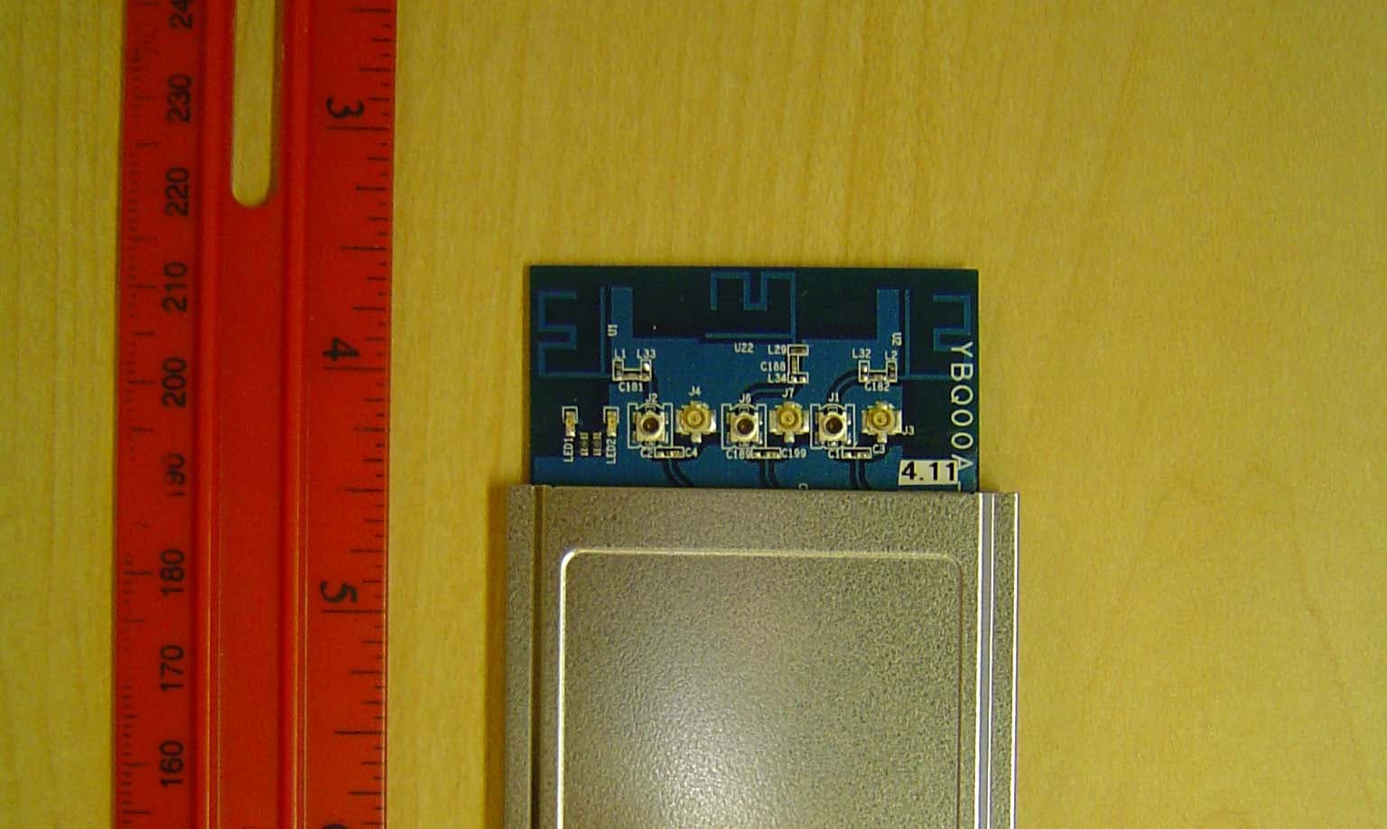
Click to zoom
Application Details
- Equipment Class
- DTS - Digital Transmission System
- Date of Grant
- May 21, 2006
- Application Purpose
- Original Equipment
- Date of Application
- May 19, 2006
- Equipment Note
- MIMO Cardbus Module
- Frequency Range
- 2412.00000000 - 2462.00000000
- Company
- Netgear Incorporated
- Country
- United States
Documents & Files
Document Text
Text extracted from the exhibit documents filed with the FCC. Open a document above to read the original.
Users Manual
Introduction: WNCRDBSB WLAN Card User's Guide - DRAFT Before you begin Things you should know WNCRDBSB network Before you begin Obtain the following information from your network administrator (if you are a home user, obtain this information from the person that installed your wireless access point): l Network names (SSID) of the specific wireless networks that you want to connect to. l WEP (Wired Equivalent Privacy) key information (if any) for the networks you want to connect to. l For Microsoft® Windows® networking, your customer name and workgroup name. l For your network account, your user name and password. l Your IP address (if not using a DHCP server) Things you should know When you start your computer, your WNCRDBSB WLAN card detects certain wireless networks that are within range. Before you can connect to these and other wireless networks, you must configure a profile for each network using the information you obtained from your network administrator. WEP is a security protocol for wireless local area networks (defined in the IEEE 802.11g standard) that encrypts data sent over radio waves. The use of the WEP key is optional and can be enabled or disabled. If the network you are connecting to has enabled WEP, you must also enable WEP in the network profile and set the WEP key to match the WEP key used by the network. Otherwise, you cannot connect to the network. WNCRDBSB network The WNCRDBSB solution allows you to make a wireless connection to a network, as illustrated below. Back to top Using the Broadcom Wireless Utility: Broadcom AirForce™ 54g™ and Intensi-fi™ Wireless Network Adapter User Guide Back to Contents Page Using the Broadcom Wireless Utility: Broadcom AirForce™ 54g™ and Intensi-fi™ Wireless Network Adapter User Guide Overview Utility Components Overview The Broadcom Wireless Utility enables you to do the following network tasks: l Manage your wireless networks and create network connection profiles (Wireless Networks tab) l Connect to available networks (utility icon in notification area) l Get information about the network status and signal and noise of your network connection (Link Status tab) l View current and accumulated statistics (Statistics tab) l Find out which broadcasting networks are in range and search for nonbroadcasting networks (Site Monitor tab) l Run tests on the wireless network adapter (Diagnostics tab) l Get date and version information about the utility, and software, hardware, and location details about your wireless network adapter ( Information tab) l Manually add or delete trusted servers and enable the manual acceptance or rejection of auto- provisioning and A-ID group changes ( Wireless Networks tab) l Manually import EAP-FAST PACs (Wireless Networks tab) In the utility, you can open Wireless Network Wizard to connect to a basic network or create an ad hoc network, or you can open the Wireless Network Connection Settings tool to connect to an advanced network. To do any of the other tasks, click the tab that is associated with the described task. To start using the utility, right-click the utility icon in the notification area, and then click Open Utility. If the icon is not available, open Broadcom Wireless Utility in Control Panel. NOTE: The utility icon may not appear exactly as shown here. See " Table 1. Signal Strength Indicated by the Broadcom Wireless Utility Icon." Utility Components Utility components include the utility icon in the notification area, the six utility tabs, and Wireless Network Connection Settings. file:///P|/User%20Manuals/WLANCard-UM302_LaLa/HTML/utility.htm (1 of 12)4/25/2006 1:57:41 PM Using the Broadcom Wireless Utility: Broadcom AirForce™ 54g™ and Intensi-fi™ Wireless Network Adapter User Guide Utility Icon To do any of the following tasks or operations, right-click the utility icon, and then click the appropriate item. l Open the on-line Broadcom AirForce™ 54g™ and Intensi-fi™ Wireless Network Adapter User Guide (Help Files) l Open About WLAN Card Utility to view links to Broadcom and Broadcom Customer Support websites and to view the version and date of the utility (About) l Hide the utility icon (Hide Tray Icon) l Disable or enable the radio (Disable/Enable Radio) l Connect to any of the networks for which you have created a connection profile and are within range (Connect To) l Open the utility to the Wireless Networks tab (Open Utility) l Open the utility to the Link Status tab to view information about the connection (Status) l Display a log of your wireless network events (Display Log) Wireless Networks Tab The Wireless Networks tab has tools that enable you to do the following: l Use the utility to manage your wireless networks l Add a network connection profile l Edit or remove a network connection profile l Change the order in which profiles are listed under Preferred network connections l Connect to any listed network without changing its order in the list l Disable or enable the radio (Disable/Enable Radio) l Show or hide the utility icon in the notification area l Choose which type of network to access l Lock or unlock a preferred network connection profile l Save your wireless network connection profiles as a WPN file l Import a WPN file l Manually add or delete trusted servers and enable the manual acceptance or rejection of auto- provisioning and A-ID group changes l Manually import EAP-FAST PACS On the Add menu, you can use either the wireless network wizard that is available from Broadcom Wireless Utility (see Connecting to a Basic Network or Creating an Ad Hoc Network Using the Wireless Network Wizard") or the utility (see "Connecting to an Advanced Network Using the Broadcom Wireless Utility") to add a network connection profile. To use the utility to manage your wireless networks, select the Let this tool manage your wireless networks check box. To add a network connection profile, click the Add arrow, and then click either Use Wizard (basic network) or Use Utility (advanced network). …
Text truncated - open the document above for the full version.
Cover Letter(s)
Specification 1. Electrical Properties : 1.1 Frequency Range............ 1.2 Impedance .................. 1.3 VSWR ..................... ... 1.4 Return Loss.................. 1.5 Radiation ..................... 1.6 Gain(peak)................... 1.8dBi (excluding cable loss) 1.7 Cable Loss.................. ...0.6dB 1.8 Polarization............... ...Linear Vertical 1.9 Admitted Power............ 2. Physical Properties : 2.1 Cable...........................φ1.13 Coaxial Cable 2.2 Antenna Cover............ ...ABS+PC 2.3 Operating Temp. ......... ...-20 ~ +65 2.4 Storage Temp. ............ ...-30 ~ +75 2.5 Color ........................ .White 2.6 Connector.................. ...HRS 1W 2.4GHz ~ 2.5GHz 50Ω Nominal 1.92 Max. -10 dB Maximum RF Antenna Cable Assembly Omni-directional 1 2 RF Antenna Assembly P/NO : C147-510271-A SPEC : 2.4GHz 3/21/2006 3 3/21/2006 0 345 330 315 300 285 270 255 240 225 210 195 180 165 150 135 120 105 90 75 60 45 30 15 -30-20-100 dB Far-field amplitude of 150-V.nsi 2.400000 GHz2.450000 GHz2.500000 GHz 4 3/21/2006 0 345 330 315 300 285 270 255 240 225 210 195 180 165 150 135 120 105 90 75 60 45 30 15 -30-20-100 dB Far-field amplitude of 150-H01.nsi 2.400000 GHz2.450000 GHz2.500000 GHz 5 6 7 8 9
Cover Letter(s)
NETGEAR, INC. 4500 Great America Parkway, Santa Clara, CA95054 U.S.A. Date April 27 th 2006 Elliott TCB 684 West Maude Ave. Sunnyvale, CA. 94085 FCC ID: PY306200045 Dear Examiner: I am writing to avoid the possibility of an inadvertent disclosure of proprietary information. The accompanying Form 731 is being filed with the commission on our behalf by Elliott Laboratories, Inc., a consulting and testing laboratory. Included as exhibits with the enclosed application are block diagrams, schematics, and a detailed description of the theory of operation of the device. It is our intention to provide Elliott TCB and the commission with a full disclosure of our product so that its merits can be evaluated. Indeed, we are pleased to provide any further information that the commission might wish to see. It is not our intention, however, to make our proprietary process a matter of public record. In view of the fact that the block diagrams, schematics, and associated theory of operation disclose the mechanism of our process, we ask that these portions (block diagrams, schematics, and theory of operation) of our application be withheld from public inspection as provided under FCC section 0.459. These documents contain details of the proprietary operation of product. These details are not readily discernible - even to technically sophisticated individuals - from our hardware and constitute trade secrets. We request therefore that these documents be segregated from the body of our evaluation report and withheld from public inspection. Thank you for your attention. Please let the undersigned know if Elliott TCB or the Commission disagrees with our position or requires further justification. Sincerely, Mark Gandler Sr. Compliance Engineer
Cover Letter(s)
May 4, 2006 Elliott TCB 684 West Maude Avenue Sunnvyale, CA 94085 Dear Application Examiner: Modular approval for the device is being requested. The device meets the eight requirements outlined in FCC Public Notice DA 00-1407 Released: June 26, 2000. Netgear is seeking a Limited Modular Approval. The module will be used exclusively by and in Netgear’s final products and will not be sold to OEM’s or to the general public. Netgear will be responsible for compliance of the module when installed in its final host. Netgear is aware that the module can only be used for mobile applications and cannot be used in “portable” (less than 20 cm separation distance) applications 1) The modular transmitter must have its own RF shielding. The EUT contains its own RF shielding (refer to external and internal photos) 2) The modular transmitter must have buffered modulation/data inputs. EUT has buffered data inputs to insure compliance with Part 15 requirements under conditions of excessive data rates or over- modulation. Please refer to the schematics. 3) The modular transmitter must have its own power supply regulation. The EUT has its own power supply regulation to insure compliance with Part 15 requirements regardless of the quality or level of external DC supplying the module from the host unit. Refer to Schematics. 4) The modular transmitter must comply with the antenna requirements of Section 15.203 and 15.204(c). The module will be installed inside final host and the user will not have access to the antennas. 5) The modular transmitter must be tested in a stand-alone configuration. The EUT was tested outside a system host. 6) The modular transmitter must be labeled with its own FCC ID number, and, if the FCC ID is not visible when the module is installed inside another device, then the outside of the device into which the module is installed must also display a label referring to the enclosed module. The devices containing the module will be labeled with the FCC ID of the module. 7) The modular transmitter must comply with any specific rule or operating requirements applicable to the transmitter and the manufacturer must provide adequate instructions along with the module to explain any such requirements. A copy of these instructions must be included in the application for equipment authorization. The operating limitations are fully understood by applicant. 8) The modular transmitter must comply with any applicable RF exposure requirements. The MPE calculation shows that the device meets the RF exposure requirements provided that a separation of at least 20cm is maintained between the EUT and people in its vicinity. The installation and user manuals for products containing this module will all reference this requirement. 9) The final device is designed for mobile or fixed operation (Portable is not permitted – Reference TCB Exclusion List (17 July 2002) II(g)). The final device will be used for mobile or fixed operation as detailed in the manual. Netgear will use the module only in its products and will not sell to OEM’s or to the general public. 10) The maximum antenna gain to allow compliance with RF exposure requirements is listed on the Grant of Certification for the module Maximum antenna gain info and specifications have been uploaded into the RF exposure exhibit for review and record. 11) The licensed module must have a FCC ID label on the module itself. That FCC ID label must be visible through a window on the final device or it must be visible when an access panel, door or cover is easily removed. If not, a second label must be placed on the outside of the final device that contains the following text: "Contains FCC ID: xxxyyyzzz” Refer to #6. The applicant is aware that a label will be required outside the final product if the label on the module is not visible when purchased or open. If there are any questions or if further information is needed, please contact Elliott Laboratories for assistance. Sincerely, Juan Martinez Senior EMC Engineer JM/dmg
ID Label/Location Info
NETGEAR WNCRDBSB FCC ID label & Location FCC ID: PY306200045 Module FCC Label NETGEAR WNCRDBSBFCC ID: PY306200045 NETGEAR WNCRDBSB FCC ID label & Location FCC ID: PY306200045 System FCC Label
RF Exposure Info
MPE Exposure Formula: S = ( P X G ) / ( 4 X π X d^2 ) where: S = power density P = transmitter conducted power in (mW) G = antenna numeric gain d = distance to radiation center (m) or (.02^2 ) = .020 m 2412 MHz (802.11b) Gain =1.3NumericEUT ant.:1.2dBi Power = 58mWEUT power:17.6dBm Frequency =2412MHzMPE limit:1 mW/cm^2 Cable Loss =0dB EIRP =75.86mW75.86mW R (cm) = S (20cm) = 2437 MHz (802.11b) Gain =1.3NumericEUT ant.:1.2dBi Power = 74mWEUT power:18.7dBm Frequency =2437MHzMPE limit:1 mW/cm^2 Cable Loss =0dB EIRP =97.72mW97.72mW R (cm) = S (20cm) = 2462 MHz (802.11b) Gain =1.3NumericEUT ant.:1.2dBi Power = 55mWEUT power:17.4dBm Frequency =2462MHzMPE limit:1 mW/cm^2 Cable Loss =0dB EIRP =72.44mW72.44mW R (cm) = S (20cm) = Enter Data in Linear Units 0.0152.4569429 Enter Data in Linear Units 2.78865680.019 Enter Data in Linear Units 2.40101610.014 2412 MHz (802.11g) Gain =1.3NumericEUT ant.:1.2dBi Power = 55mWEUT power:17.4dBm Frequency =2412MHzMPE limit:1 mW/cm^2 Cable Loss =0dB EIRP =72.44mW72.44mW R (cm) = S (20cm) = 2437 MHz (802.11g) Gain =1.3NumericEUT ant.:1.2dBi Power = 71mWEUT power:18.5dBm Frequency =2437MHzMPE limit:1 mW/cm^2 Cable Loss =0dB EIRP =93.33mW93.33mW R (cm) = S (20cm) = 2462 MHz (802.11g) Gain =1.3NumericEUT ant.:1.2dBi Power = 40mWEUT power:16dBm Frequency =2462MHzMPE limit:1 mW/cm^2 Cable Loss =0dB EIRP =52.48mW52.48mW R (cm) = S (20cm) = Enter Data in Linear Units 2.40101610.014 Enter Data in Linear Units 2.72517920.019 Enter Data in Linear Units 2.04359610.010 2412 MHz (802.11n, 20 MHz) Gain =2.6NumericEUT ant.:4.2dBi Power = 69mWEUT power:18.4dBm Frequency =2412MHzMPE limit:1 mW/cm^2 Cable Loss =0dB EIRP =181.97mW181.97mW R (cm) = S (20cm) = 2437 MHz (802.11n, 20 MHz) Gain =2.6NumericEUT ant.:4.2dBi Power = 129mWEUT power:21.1dBm Frequency =2437MHzMPE limit:1 mW/cm^2 Cable Loss =0dB EIRP =338.84mW338.84mW R (cm) = S (20cm) = 2462 MHz (802.11n, 20 MHz) Gain =2.6NumericEUT ant.:4.2dBi Power = 62mWEUT power:17.9dBm Frequency =2462MHzMPE limit:1 mW/cm^2 Cable Loss =0dB EIRP =162.18mW162.18mW R (cm) = S (20cm) = Enter Data in Linear Units 3.80535400.036 Enter Data in Linear Units 5.19272190.067 Enter Data in Linear Units 3.59248590.032 2422 MHz (802.11n, 40 MHz) Gain =2.6NumericEUT ant.:4.2dBi Power = 58mWEUT power:17.6dBm Frequency =2422MHzMPE limit:1 mW/cm^2 Cable Loss =0dB EIRP =151.36mW151.36mW R (cm) = S (20cm) = 2437 MHz (802.11n, 40 MHz) Gain =2.6NumericEUT ant.:4.2dBi Power = 59mWEUT power:17.7dBm Frequency =2437MHzMPE limit:1 mW/cm^2 Cable Loss =0dB EIRP =154.88mW154.88mW R (cm) = S (20cm) = 2452 MHz (802.11n, 40 MHz) Gain =2.6NumericEUT ant.:4.2dBi Power = 41mWEUT power:16.1dBm Frequency =2452MHzMPE limit:1 mW/cm^2 Cable Loss =0dB EIRP =107.15mW107.15mW R (cm) = S (20cm) = Enter Data in Linear Units 3.47052410.030 Enter Data in Linear Units 3.51071090.031 Enter Data in Linear Units 2.92008210.021
Test Report
File: R63793 Page 1 of 25 2016-01 Electromagnetic Emissions Test Report and Application for Grant of Equipment Authorization pursuant to Industry Canada RSS-Gen Issue 1 / RSS 210 Issue 6 FCC Part 15, Subpart C Section 15.247(DTS) on the Netgear Transmitter Model: WNCRDBSB FCC ID: PY306200045 GRANTEE: Netgear 4500 Great America Parkway Santa Clara, CA 95054 TEST SITE: Elliott Laboratories, Inc. 41039 Boyce Road Fremont, CA 94538 REPORT DATE: April 28, 2006 FINAL TEST DATE: April 25 and April 26, 2006 AUTHORIZED SIGNATORY: ______________________________ Juan Martinez Senior EMC Engineer Elliott Laboratories, Inc. is accredited by the A2LA, certificate number 2016-01, to perform the test(s) listed in this report. This report shall not be reproduced, except in its entirety, without the written approval of Elliott Laboratories, Inc. Elliott Laboratories, Inc. -- EMC Department Test Report Report Date: April 28, 2006 File: R63793 Page 2 of 25 Equipment Name and Model: Transceiver, WNCRDBSB Manufacturer: Netgear 4500 Great America Parkway Santa Clara, CA 95054 Tested to applicable standard: Industry Canada RSS-Gen Issue 1 RSS 210 Issue 6 “Low-power Licence-exempt Radiocommunication Devices (All Frequency Bands): Category I Equipment” Test Report Prepared For: Mark Gandler Netgear 4500 Great America Parkway Santa Clara, CA 95054 Measurement Facility Description Filed With Department of Industry: Departmental Acknowledgement Number: IC4549-3 Dated March 10, 2009 Declaration of Compliance I declare that the testing was performed or supervised by me; that the test measurements were made in accordance with the above mentioned departmental standards (through the use of ANSI C63.4: 2003 as referenced by FCC Part 15 and by section 1.0 of RSS-212, Issue 1, “Test Facilities and Test Methods for Radio Equipment” / RSS-Gen Issue 1); and that the equipment performed in accordance with the data submitted in this report. Signature ______________________________ Name Juan Martinez Title Senior EMC Engineer Elliott Laboratories Inc. Address 684 W. Maude Ave Sunnyvale, CA 94086 USA Date: April 28, 2006 Elliott Laboratories, Inc. -- EMC Department Test Report Report Date: April 28, 2006 File: R63793 Page 3 of 25 TABLE OF CONTENTS COVER PAGE............................................................................................................................................................. 1 TABLE OF CONTENTS ..........................................................................................................................................3 SCOPE........................................................................................................................................................................5 OBJECTIVE ..............................................................................................................................................................6 STATEMENT OF COMPLIANCE .........................................................................................................................7 TEST RESULTS SUMMARY..................................................................................................................................8 DIGITAL TRANSMISSION SYSTEMS (2400 – 2483.5MHZ) ............................................................................8 GENERAL REQUIREMENTS APPLICABLE TO ALL BANDS ........................................................................9 MEASUREMENT UNCERTAINTIES ...................................................................................................................9 EQUIPMENT UNDER TEST (EUT) DETAILS ..................................................................................................10 GENERAL............................................................................................................................................................10 ANTENNA SYSTEM ..........................................................................................................................................10 ENCLOSURE .......................................................................................................................................................10 MODIFICATIONS ...............................................................................................................................................10 SUPPORT EQUIPMENT.....................................................................................................................................10 EUT INTERFACE PORTS ..................................................................................................................................10 EUT OPERATION ...............................................................................................................................................11 TEST SITE ...............................................................................................................................................................12 GENERAL INFORMATION ...............................................................................................................................12 CONDUCTED EMISSIONS CONSIDERATIONS.............................................................................................12 RADIATED EMISSIONS CONSIDERATIONS.................................................................................................12 MEASUREMENT INSTRUMENTATION ..........................................................................................................13 RECEIVER SYSTEM ..........................................................................................................................................13 INSTRUMENT CONTROL COMPUTER ..........................................................................................................13 LINE IMPEDANCE STABILIZATION NETWORK (LISN) .............................................................................13 POWER ME…
Text truncated - open the document above for the full version.
Test Setup Photos
Radiated Emissions Test Configuration Photographs Radiated Emissions Test Configuration Photographs AC Power Line Conducted Emissions Test Configuration Photographs AC Power Line Conducted Emissions Test Configuration Photographs
Contact Information
Applicant
David Kay
Technical Contact
Elliott labsJuan Martinez
408 245 7800
684 West Maude Ave · Sunnyvale, California · United States
Test Firm
Elliott Laboratories Inc.David Bare
Technical Specifications
| # | Rule Parts | Frequency Range | Power Output |
|---|---|---|---|
| 1 | 15C | 2.41 GHz - 2.46 GHz | 138.35 mW |
Other Applications from Netgear Incorporated

PY325100647
Aug 04, 2026BE5000 Dual-Band PoE 2.5G Insight Managed WiFi 7 Outdoor Access Point
Equipment Class
DTS - Digital Transmission SystemPY325300652
May 12, 2026BE5000 Dual-Band PoE 2.5G Insight Managed WiFi 7 Access Point
Equipment Class
NII - Unlicensed National Information Infrastructure TXPY325400656
Apr 16, 2026Orbi Outdoor Satellite
Equipment Class
DTS - Digital Transmission SystemPY324400640
Dec 12, 2025Orbi 11BE WiFi 7 Tri-band Router, Orbi 11BE WiFi 7 Tri-band Satellite
Equipment Class
NII - Unlicensed National Information Infrastructure TXPY324100618
Jul 31, 2024Nighthawk 5G Mobile Router
Equipment Class
PCB - PCS Licensed Transmitter