PY310200134N 150 Wireless Router
Netgear Incorporated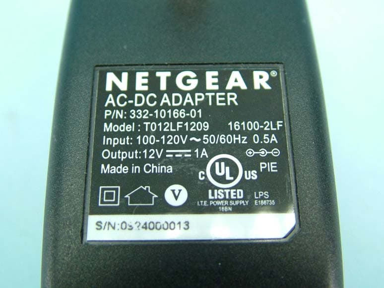
Click to zoom
Application Details
- Equipment Class
- DTS - Digital Transmission System
- Date of Grant
- Aug 01, 2010
- Application Purpose
- Original Equipment
- Date of Application
- Aug 01, 2010
- Equipment Note
- N 150 Wireless Router
- Frequency Range
- 2412.00000000 - 2462.00000000
- Company
- Netgear Incorporated
- Country
- United States
Documents & Files
Document Text
Text extracted from the exhibit documents filed with the FCC. Open a document above to read the original.
Users Manual
August 2010 v1.0 NETGEAR, Inc. 350 E. Plumeria Drive San Jose, CA 95134 USA N 150 Wireless Router WNR1000 v2h2 User Manual ii v1.0, August 2010 ©2010 by NETGEAR, Inc. All rights reserved. Product Registration, Support, and Documentation Register your product at http://www.netgear.com/register. Registration is required before you can use our telephone support service. Product updates and Web support are always available at http://www.netgear.com/support. Setup documentation is available on the CD, on the support website, and on the documentation website. When the wireless router is connected to the Internet, click the Knowledge Base or the Documentation link under Web Support on the main menu to view support information. Trademarks NETGEAR and the NETGEAR logo are registered trademarks, and RangeMax and Smart Wizard are trademarks of NETGEAR. Inc. in the United States and/or other countries. Microsoft, Windows, and Windows NT are registered trademarks and Windows Vista is a trademark of Microsoft Corporation. Other brand and product names are registered trademarks or trademarks of their respective holders. Statement of Conditions In the interest of improving internal design, operational function, and/or reliability, NETGEAR reserves the right to make changes to the products described in this document without notice. NETGEAR does not assume any liability that may occur due to the use or application of the product(s) or circuit layout(s) described herein. Certificate of the Manufacturer/Importer It is hereby certified that the N 150 Wireless Router WNR1000 v2h2 has been suppressed in accordance with the conditions set out in the BMPT-AmtsblVfg 243/1991 and Vfg 46/1992. The operation of some equipment (for example, test transmitters) in accordance with the regulations may, however, be subject to certain restrictions. Please refer to the notes in the operating instructions. Federal Office for Telecommunications Approvals has been notified of the placing of this equipment on the market and has been granted the right to test the series for compliance with the regulations. Bestätigung des Herstellers/Importeurs Es wird hiermit bestätigt, daß das N 150 Wireless Router WNR1000 v2h2 gemäß der im BMPT-AmtsblVfg 243/ 1991 und Vfg 46/1992 aufgeführten Bestimmungen entstört ist. Das vorschriftsmäßige Betreiben einiger Geräte (z.B. Testsender) kann jedoch gewissen Beschränkungen unterliegen. Lesen Sie dazu bitte die Anmerkungen in der Betriebsanleitung. Das Bundesamt für Zulassungen in der Telekommunikation wurde davon unterrichtet, daß dieses Gerät auf den Markt gebracht wurde und es ist berechtigt, die Serie auf die Erfüllung der Vorschriften hin zu überprüfen. Regulatory Compliance Information This section includes user requirements for operating this product in accordance with National laws for usage of radio spectrum and operation of radio devices. Failure of the end-user to comply with the applicable requirements may result in unlawful operation and adverse action against the end-user by the applicable National regulatory authority. v1.0, August 2010 iii NOTE:This product's firmware limits operation to only the channels allowed in a particular Region or Country. Therefore, all options described in this user's guide may not be available in your version of the product. Europe – EU Declaration of Conformity This device complies with the essential requirements of the R&TTE Directive 1999/5/EC. The following test methods have been applied in order to prove presumption of conformity with the essential requirements of the R&TTE Directive 1999/5/EC: •EN 60950-1: 2001 Safety of information technology equipment •EN 300 328 V1.7.1 (2006-10) Electromagnetic compatibility and Radio spectrum Matters (ERM); Wideband transmission systems; Data transmission equipment operating in the 2,4 GHz ISM band and using wide band modulation techniques; Harmonized EN covering essential requirements under article 3.2 of the R&TTE Directive •EN 301 489-17 V1.2.1 (2002-08) and EN 301 489-1 V1.4.1 (2002-08) Electromagnetic compatibility and Radio spectrum Matters (ERM); ElectroMagnetic Compatibility (EMC) standard for radio equipment and services; Part 17: Specific conditions for 2,4 GHz wideband transmission systems and 5 GHz high performance RLAN equipment This device is a 2.4 GHz wideband transmission system (transceiver), intended for use in all EU member states and EFTA countries under the following conditions and/or with the following restrictions: •In Italy the end-user should apply for a license at the national spectrum authorities in order to obtain authorization to use the device for setting up outdoor radio links and/or for supplying public access to telecommunications and/or network services. •This device may not be used for setting up outdoor radio links in France and in some areas the RF output power may be limited to 10 mW EIRP in the frequency range of 2454 - 2483.5 MHz. For detailed information the end-user should contact the national spectrum authority in France. Europe – Declaration of Conformity in Languages of the European Community Č esky [Czech] [NETGEAR Inc.] tímto prohlašuje, že tento [WNR1000 v2h2] je ve shode se základními požadavky a dalšími príslušnými ustanoveními smernice 1999/5/ES. Dansk [Danish] Undertegnede [NETGEAR Inc.] erklærer herved, at følgende udstyr [WNR1000v2h2] overholder de væsentlige krav og øvrige relevante krav i direktiv 1999/5/EF. Deutsch [German] Hiermit erklärt [NETGEAR Inc.], dass sich das Gerät [WNR1000 v2h2] in Übereinstimmung mit den grundlegenden Anforderungen und den übrigen einschlägigen Bestimmungen der Richtlinie 1999/5/EG befindet. Eesti [Estonian] Käesolevaga kinnitab [NETGEAR Inc.] seadme [WNR1000 v2h2] vastavust direktiivi 1999/ 5/EÜ põhinõuetele ja nimetatud direktiivist tulenevatele teistele asjakohastele sätetele. EnglishHereby, [NETGEAR Inc.], declares that this [WNR1000 v2h2] is in compliance with the essential requirements and other relevant provisions of Dir…
Text truncated - open the document above for the full version.
Users Manual
Fine-Tuning Your Network5-14 v1.0, August 2010 Optimizing Wireless Performance The speed and operating distance or range of your wireless connection can vary significantly based on the physical placement of the wireless router. You should choose a location for your router that will maximize the network speed. The following list describes how to optimize wireless router performance. •Identify critical wireless links. If your network has several wireless devices, decide which wireless devices need the highest data rate, and locate the router near them. Many wireless products have automatic data-rate fallback, which allows increased distances without loss of connectivity. This also means that devices that are farther away might be slower. Therefore, the most critical links in your network are those where the traffic is high and the distances are great. Optimize those first. •Choose placement carefully. For best results, place your router: –Near the center of the area in which your computers will operate. –In an elevated location such as a high shelf where the wirelessly connected computers have line-of-sight access (even if through walls). –Avoid obstacles to wireless signals. –Keep wireless devices at least 2 feet from large metal fixtures such as file cabinets, refrigerators, pipes, metal ceilings, reinforced concrete, and metal partitions. –Keep away from large amounts of water such as fish tanks and water coolers. •Reduce interference. –Avoid windows unless communicating between buildings. –Place wireless devices away from various electromagnetic noise sources, especially those in the 2400–2500 MHz frequency band. Common noise-creating sources are: •Computers and fax machines (no closer than 1 foot) •Copying machines, elevators, and cell phones (no closer than 6 feet) Note: Failure to follow these guidelines can result in significant performance degradation or inability to wirelessly connect to the router. For complete range and performance specifications, click the link to the online document “Wireless Networking Basics” in Appendix B. Fine-Tuning Your Network5-15 v1.0, August 2010 •Microwave ovens (no closer than 10 feet) •Choose your settings. –Use a scanning utility to determine what other wireless networks are operating nearby, and choose an unused channel. –Turn off SSID broadcast, and change the default SSID. Other nearby devices might automatically try to connect to your network several times a second, which can cause significant performance reduction. •Use WMM to improve the performance of voice and video traffic over the wireless link. Changing the MTU Size The Maximum Transmission Unit (MTU) is the largest data packet a network device transmits. When one network device communicates across the Internet with another, the data packets travel through many devices along the way. If any device in the data path has a lower MTU setting than the other devices, the data packets must be split or “fragmented” to accommodate the one with the smallest MTU. The best MTU setting for NETGEAR equipment is often just the default value, and changing the value might fix one problem but cause another. Leave MTU unchanged unless one of these situations occurs: •You have problems connecting to your ISP, or other Internet service, and either the technical support of the ISP or of NETGEAR recommends changing the MTU size. These might require an MTU change: –A secure Web site that will not open, or displays only part of a Web page –Yahoo e-mail –MSN –America Online’s DSL service •You use VPN and have severe performance problems. •You used a program to optimize MTU for performance reasons, and now you have connectivity or performance problems. Note: An incorrect MTU setting can cause Internet communication problems such as the inability to access certain Web sites, frames within Web sites, secure login pages, or FTP or POP servers. Fine-Tuning Your Network5-16 v1.0, August 2010 If you suspect an MTU problem, a common solution is to change the MTU size to 1400. If you are willing to experiment, you can gradually reduce the MTU size from the maximum value of 1500 until the problem goes away. Table 5-1 describes common MTU sizes and applications. To change the MTU size: 1.In the main menu, under Advanced, select WAN Setup. 2.In the MTU Size field, enter a new size between 64 and 1500. 3.Click Apply to save the new configuration. Overview of Home and Small Office Networking Technologies Common connection types and their speed and security considerations are: •Broadband Internet. Your Internet connection speed is determined by your modem type, such as ADSL or cable modem, as well as the connection speed of the sites to which you connect, and general Internet traffic. ADSL and cable modem connections are asymmetrical, meaning they have a lower data rate to the Internet (upstream) than from the Internet (downstream). Keep in mind that when you connect to another site that also has an asymmetrical connection, the data rate between your sites is limited by each side’s upstream data rate. A typical residential ADSL or cable modem connection provides a downstream throughput of about 1 to 3 megabits per second (Mbps). Newer technologies such as ADSL2+ and Fiber to the Home (FTTH) will increase the connection speed to tens of Mbps. Table 5-1. Common MTU Sizes MTUApplication 1500The largest Ethernet packet size and the default value. This is the typical setting for non- PPPoE, non-VPN connections, and is the default value for NETGEAR routers, adapters, and switches. 1492Used in PPPoE environments. 1472Maximum size to use for pinging. (Larger packets are fragmented.) 1468Used in some DHCP environments. 1460Usable by AOL if you do not have large e-mail attachments, for example. 1436Used in PPTP environments or with VPN. 1400Maximum size for AOL DSL. 576Typical value to connect to dial-up ISPs. Fine-Tuning Your Network5-17 v1.0,August 2010 •Wireless. Your N 150 Wireless Router WNR1000 v2h2 provides a wireless data throu…
Text truncated - open the document above for the full version.
Attestation Statements
Netgear Inc. 350 East Plumeria Drive San Jose, CA 95134 Date: 2010-07-01 General Declaration General Declaration General Declaration General Declaration FCC ID: PY310200134 We, Netgear Inc. declares that the device does not have “Ad Hoc on non-US frequencies” and/or “on DFS frequencies”. If you have any questions regarding the declaration, please don’t hesitate to contact us. Thank you! Sincerely yours, ------------------------------------------------- Mark Gandler / project manager Netgear Inc. TEL.: 408-907-8000 FAX: 408-907-8097 E-mail: [email protected]
Cover Letter(s)
FCC ID: PY310200134 Date: 2010-07-01 Federal Communications Commission Authorization and Evaluation Division Confidentiality Request Pursuant to Sections 0.457 and 0.459 of the Commission’s Rules, the Applicant hereby requests confidential treatment of information accompanying this Application as outlined below: Schematics Block diagram The above materials contain trade secrets and proprietary information not customarily released to the public. The public disclosure of these matters might be harmful to the Applicant and provide unjustified benefits to its competitors. The Applicant understands that pursuant to Rule 0.457, disclosure of this Application and all accompanying documentation will not be made before the date of the Grant for this application. Sincerely, ------------------------------------------------- Mark Gandler/ project manager Netgear Inc. TEL.: 408-907-8000 FAX: 408-907-8097 E-mail: [email protected] Netgear Inc. 350 East Plumeria Drive San Jose, CA 95134
Cover Letter(s)
Netgear Inc. 350 East Plumeria Drive San Jose, CA 95134 AUTHORIZATION LETTER FCC ID: PY310200134 Date:2010/7/1 To whom it may concern: We, the undersigned UNetgear Inc.U hereby authorize Bureau Veritas Consumer Products Services (H.K.) Ltd., Taoyuan Branch (BV CPS Taoyuan) of Taiwan to act on our behalf in all matters relating to all processes required in FCC Part15C and any communication needed with the national authority. Any and all acts carried out by BV CPS Taoyuan on our behalf shall have the same effects as acts of our own. If you have any questions regarding the authorization, please don’t hesitate to contact us. Thank you! Sincerely yours, ------------------------------------------------- Mark Gandler / project manager UNetgear Inc.U TEL.: 408-907-8000 FAX: 408-907-8097 E-mail: [email protected]
External Photos
Page 1 CONSTRUCTION PHOTOS OF EUT Adapter model 1: T012LF1209 16100-2LF Page 2 Page 3 Adapter model 2: MT12-Y120100-A1 Page 4 Page 5 Page 6
ID Label/Location Info
SHEET: AUTHOR:TITLE: P/N: REV: THIS DOCUMENT AND THE DATA DISCLOSED HEREIN OR WHEREWITH IS NOT TO BE REPRODUCED, USED OR DISCLOSED IN WHOLE OR IN PART TO ANYONE WITHOUT THE PERMISSION OF NETGEAR, INC. REV DESCRIPTION OF REVISION ENG APPD DATE 7 01AW-11251-011 of 1 AW,WNR1000,V2H2,PLBLR HU 21MAY10R HUINITIAL DOCUMENT CREATION 01 Pantone 877C Pantone Process Black C NOTE: 1. REFER TO NETGEAR SPEC. DOC-00093 FOR COLOR TOLERANCES. 2. INK COLOR IS SHOWN TO THE RIGHT. 3. DIE LINES ARE MAGENTA COLOR AND DO NOT PRINT. 4. MAC & SERIAL NUMBERS TO BE PRINTED BY THE ODM. 5. SEE NTGR DOC-00112 FOR SN STANDARD. 6. NTGR SN AND MAC ADDRESS BARCODE TO BE ENCODED AIM USS CODE39 AND INCLUDE PRINTED CHARACTERS BELOW BARCODE. 7. INSURE COUNTRY OF ORIGIN IS CORRECT. A. IF COUNTRY OF ORIGIN IS PRE-PRINTED, UNHIDE THE APPROPRIATE COUNTRY OF ORIGIN LAYER AND INCLUDE COUNTRY OF ORIGIN ON LABEL. B. IF COUNTRY OF ORIGIN IS POST-PRINTED USING A THERMAL PRINTER (OR EQUIVALENT), OMIT TEXT FROM ARTWORK (USE LAYERS).
ID Label/Location Info
Label Location
Internal Photos
Page 7 Page 8 Page 9 Page 10
Operational Description
FCC ID: PY310200134 Report No.: RF990629C08 OPERATIONAL DESCRIPTION This device is a N 150 Wireless Router, which operates in the 2.4GHz frequency spectrum with throughput of up to 150Mbps which OFDM technique will be applied. If the signal to noise ratio is too poor which could not support 150Mbps, the 11Mbps data rate with DSSS technique will be applied. The transmitter of the EUT is powered by an AC adapter. The antenna is monopole antenna without antenna connector. For more detailed instruction, please take a look at the user’s manual.
RF Exposure Info
Report No.: SA990629C08 Report Format Version 3.0.1 1 RF EXPOSURE REPORT REPORT NO.: SA990629C08 MODEL NO.: WNR1000 v2h2 FCC ID: PY310200134 ACCORDING: FCC Guidelines for Human Exposure IEEE C95.1 APPLICANT: NETGEAR, INC. ADDRESS: 350 East Plumeria Drive San Jose, CA 95134 ISSUED BY: Bureau Veritas Consumer Products Services (H.K.) Ltd., Taoyuan Branch LAB ADDRESS: No. 47, 14th Ling, Chia Pau Tsuen, Lin Kou Hsiang, Taipei Hsien 244, Taiwan, R.O.C. Report No.: SA990629C08 Report Format Version 3.0.1 2 1. RF EXPOSURE LIMIT LIMITS FOR MAXIMUM PERMISSIBLE EXPOSURE (MPE) FREQUENCY RANGE (MHz) ELECTRIC FIELD STRENGTH (V/m) MAGNETIC FIELD STRENGTH (A/m) POWER DENSITY (mW/cm 2 ) AVERAGE TIME (minutes) LIMITS FOR GENERAL POPULATION / UNCONTROLLED EXPOSURE 300-1500 ... ... F/1500 30 1500-100,000 ... ... 1.0 30 F = Frequency in MHz 2. MPE CALCULATION FORMULA Pd = (Pout*G) / (4*pi*r2) where Pd = power density in mW/cm2 Pout = output power to antenna in mW G = gain of antenna in linear scale Pi = 3.1416 R = distance between observation point and center of the radiator in cm 3. CLASSIFICATION The antenna of this product, under normal use condition, is at least 20cm away from the body of the user. So, this device is classified as Mobile Device. 4. CALCULATION RESULT OF MAXIMUM CONDUCTED POWER FREQUENCY BAND (MHz) MAX POWER (dBm) ANTENNA GAIN (dBi) DISTANCE (cm) POWER DENSITY (mW/ cm 2 ) LIMIT (mW/cm 2 ) 2412-2462 24.8 2.7 20 0.112 1.00
Test Report
Report No.: RF990629C08 1 Report Format Version 3.0.1 FCC TEST REPORT REPORT NO.: RF990629C08 MODEL NO.: WNR1000 v2h2 FCC ID: PY310200134 RECEIVED: May 18, 2010 TESTED: May 20 ~ Jul. 19, 2010 ISSUED: Jul. 21, 2010 APPLICANT: NETGEAR, INC. ADDRESS: 350 East Plumeria Drive San Jose, CA 95134 ISSUED BY: Bureau Veritas Consumer Products Services (H.K.) Ltd., Taoyuan Branch LAB ADDRESS: No. 47, 14th Ling, Chia Pau Tsuen, Lin Kou Hsiang, Taipei Hsien 244, Taiwan, R.O.C. TEST LOCATION: No. 19, Hwa Ya 2nd Rd, Wen Hwa Tsuen, Kwei Shan Hsiang, Taoyuan Hsien 333, Taiwan, R.O.C. This test report consists of 71 pages in total. It may be duplicated completely for legal use with the approval of the applicant. It should not be reproduced except in full, without the written approval of our laboratory. The client should not use it to claim product certification, approval or endorsement by TAF or any government agency. The test results in the report only apply to the tested sample. Report No.: RF990629C08 2 Report Format Version 3.0.1 TABLE OF CONTENTS 1. CERTIFICATION...................................................................................................... 4 2. SUMMARY OF TEST RESULTS ............................................................................. 5 2.1 MEASUREMENT UNCERTAINTY........................................................................... 5 3. GENERAL INFORMATION ...................................................................................... 6 3.1 GENERAL DESCRIPTION OF EUT ........................................................................ 6 3.2 DESCRIPTION OF TEST MODES .......................................................................... 8 3.2.1 CONFIGURATION OF SYSTEM UNDER TEST ..................................................... 8 3.2.2 TEST MODE APPLICABILITY AND TESTED CHANNEL DETAIL .......................... 9 3.3 GENERAL DESCRIPTION OF APPLIED STANDARDS ....................................... 11 3.4 DESCRIPTION OF SUPPORT UNITS .................................................................. 11 4. TEST TYPES AND RESULTS ............................................................................... 12 4.1 RADIATED EMISSION MEASUREMENT ............................................................. 12 4.1.1 LIMITS OF RADIATED EMISSION MEASUREMENT........................................... 12 4.1.2 TEST INSTRUMENTS........................................................................................... 13 4.1.3 TEST PROCEDURES ........................................................................................... 14 4.1.4 DEVIATION FROM TEST STANDARD.................................................................. 14 4.1.5 TEST SETUP......................................................................................................... 15 4.1.6 EUT OPERATING CONDITIONS .......................................................................... 15 4.1.7 TEST RESULTS .................................................................................................... 16 4.2 CONDUCTED EMISSION MEASUREMENT ........................................................ 30 4.2.1 LIMITS OF CONDUCTED EMISSION MEASUREMENT...................................... 30 4.2.2 TEST INSTRUMENTS........................................................................................... 30 4.2.3 TEST PROCEDURES ........................................................................................... 31 4.2.4 DEVIATION FROM TEST STANDARD.................................................................. 31 4.2.5 TEST SETUP......................................................................................................... 32 4.2.6 EUT OPERATING CONDITIONS .......................................................................... 32 4.2.7 TEST RESULTS .................................................................................................... 33 4.3 6dB BANDWIDTH MEASUREMENT..................................................................... 37 4.3.1 LIMITS OF 6dB BANDWIDTH MEASUREMENT .................................................. 37 4.3.2 TEST INSTRUMENTS........................................................................................... 37 4.3.3 TEST PROCEDURE.............................................................................................. 37 4.3.4 DEVIATION FROM TEST STANDARD.................................................................. 37 4.3.5 TEST SETUP......................................................................................................... 38 4.3.6 EUT OPERATING CONDITIONS .......................................................................... 38 4.3.7 TEST RESULTS .................................................................................................... 39 4.4 MAXIMUM OUTPUT POWER ............................................................................... 43 4.4.1 LIMITS OF MAXIMUM OUTPUT POWER MEASUREMENT................................ 43 4.4.2 INSTRUMENTS ..................................................................................................... 43 4.4.3 TEST PROCEDURE.............................................................................................. 43 Report No.: RF990629C08 3 Report Format Version 3.0.1 4.4.4 DEVIATION FROM TEST STANDARD.................................................................. 44 4.4.5 TEST SETUP......................................................................................................... 44 4.4.6 EUT OPERATING CONDITIONS .......................................................................... 44 4.4.7 TEST RESULTS .................................................................................................... 45 4.5 POWER SPECTRAL DENSITY MEASUREMENT ................................................ 46 4.5.1 LIMITS OF POWER SPECTRAL DENSITY MEASUREMENT ............................. 46 4.5.2 TEST INSTRUMENTS.......…
Text truncated - open the document above for the full version.
Test Setup Photos
1 PHOTOGRAPHS OF THE TEST CONFIGURATION CONDUCTED EMISSION TEST (TEST MODE A) 2 CONDUCTED EMISSION TEST (TEST MODE B) 3 RADIATED EMISSION TEST (TEST MODE A) 4 RADIATED EMISSION TEST (TEST MODE B)
Contact Information
Applicant
David Kay
Technical Contact
Bureau Veritas CPS (H.K.) Ltd. Taoyuan BranchGary Chang
[email protected]886-3-3183232
No. 19, Hwa Ya 2nd Rd., Kwei Shan Hsiang · Taoyuan Hsien · Taiwan
Non-Technical Contact
Bureau Veritas CPS (H.K.) Ltd. Taoyuan BranchWendy Liao
[email protected]886-3-3183232
Test Firm
Bureau Veritas CPS (H.K.) Ltd. Taoyuan BranchRichard Chen
Technical Specifications
| # | Rule Parts | Frequency Range | Power Output |
|---|---|---|---|
| 1 | 15C | 2.41 GHz - 2.46 GHz | 302.00 mW |
Other Applications from Netgear Incorporated

PY325100647
Aug 04, 2026BE5000 Dual-Band PoE 2.5G Insight Managed WiFi 7 Outdoor Access Point
Equipment Class
DTS - Digital Transmission SystemPY325300652
May 12, 2026BE5000 Dual-Band PoE 2.5G Insight Managed WiFi 7 Access Point
Equipment Class
NII - Unlicensed National Information Infrastructure TXPY325400656
Apr 16, 2026Orbi Outdoor Satellite
Equipment Class
DTS - Digital Transmission SystemPY324400640
Dec 12, 2025Orbi 11BE WiFi 7 Tri-band Router, Orbi 11BE WiFi 7 Tri-band Satellite
Equipment Class
NII - Unlicensed National Information Infrastructure TXPY324100618
Jul 31, 2024Nighthawk 5G Mobile Router
Equipment Class
PCB - PCS Licensed Transmitter