PY310400146PUSH2TV
Netgear Incorporated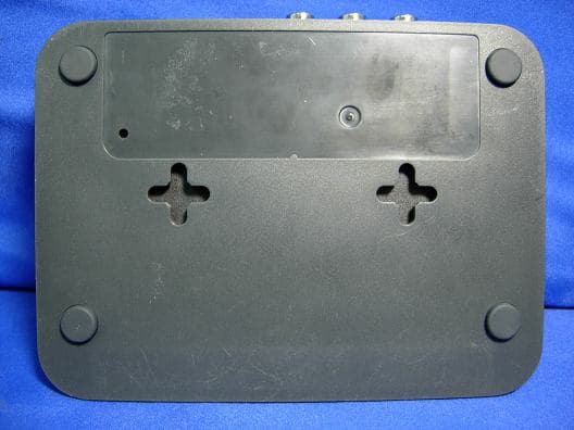
Click to zoom
Application Details
- Equipment Class
- DTS - Digital Transmission System
- Date of Grant
- Dec 20, 2010
- Application Purpose
- Original Equipment
- Date of Application
- Dec 19, 2010
- Equipment Note
- PUSH2TV
- Frequency Range
- 5755.00000000 - 5795.00000000
- Company
- Netgear Incorporated
- Country
- United States
Documents & Files
Document Text
Text extracted from the exhibit documents filed with the FCC. Open a document above to read the original.
Users Manual
202-10591-01 January 2011 NETGEAR, Inc. 350 East Plumeria Drive San Jose, CA 95134 Push 2 TV Adapter (PTV2000)/Intel Wireless Display User Manual ii v1.0, January 2011 © 2011 by NETGEAR, Inc. All rights reserved.. Technical Support Please refer to the support information card that shipped with your product. By registering your product at http://www.netgear.com/register, we can provide you with faster expert technical support and timely notices of product and software upgrades. NETGEAR, INC. Support Information Phone: 1-888-NETGEAR, for US & Canada only. For other countries, see your Support information card. E-mail: [email protected] North American NETGEAR website: http://www.netgear.com Trademarks NETGEAR, the NETGEAR logo, ProSafe, Smart Wizard, and Auto Uplink are trademarks or registered trademarks of NETGEAR, Inc. Microsoft, Windows, Windows NT and Vista are registered trademarks of Microsoft Corporation.Other brand and product names are registered trademarks or trademarks of their respective holders. Statement of Conditions In the interest of improving internal design, operational function, and/or reliability, NETGEAR reserves the right to make changes to the products described in this document without notice. NETGEAR does not assume any liability that may occur due to the use or application of the product(s) or circuit layout(s) described herein. Certificate of the Manufacturer/Importer It is hereby certified that the Push 2 TV Adapter (PTV2000)/Intel Wireless Display has been suppressed in accordance with the conditions set out in the BMPT-AmtsblVfg 243/1991 and Vfg 46/1992. The operation of some equipment (for example, test transmitters) in accordance with the regulations may, however, be subject to certain restrictions. Please refer to the notes in the operating instructions. The Federal Office for Telecommunications Approvals has been notified of the placing of this equipment on the market and has been granted the right to test the series for compliance with the regulations. Bestätigung des Herstellers/Importeurs Es wird hiermit bestätigt, daß dasPush 2 TV Adapter (PTV2000)/Intel Wireless Display gemäß der im BMPT- AmtsblVfg 243/1991 und Vfg 46/1992 aufgeführten Bestimmungen entstört ist. Das vorschriftsmäßige Betreiben einiger Geräte (z.B. Testsender) kann jedoch gewissen Beschränkungen unterliegen. Lesen Sie dazu bitte die Anmerkungen in der Betriebsanleitung. Das Bundesamt für Zulassungen in der Telekommunikation wurde davon unterrichtet, daß dieses Gerät auf den Markt gebracht wurde und es ist berechtigt, die Serie auf die Erfüllung der Vorschriften hin zu überprüfen. Voluntary Control Council for Interference (VCCI) Statement This equipment is in the Class B category (information equipment to be used in a residential area or an adjacent area thereto) and conforms to the standards set by the Voluntary Control Council for Interference by Data Processing Equipment and Electronic Office Machines aimed at preventing radio interference in such residential areas. When used near a radio or TV receiver, it may become the cause of radio interference. Read instructions for correct handling. v1.0, January 2011 iii Regulatory Compliance Information This section includes user requirements for operating this product in accordance with National laws for usage of radio spectrum and operation of radio devices. Failure of the end-user to comply with the applicable requirements may result in unlawful operation and adverse action against the end-user by the applicable National regulatory authority. NOTE:This product's firmware limits operation to only the channels allowed in a particular Region or Country. Therefore, all options described in this user's guide may not be available in your version of the product. Europe – EU Declaration of Conformity Marking by the above symbol indicates compliance with the Essential Requirements of the R&TTE Directive of the European Union (1999/5/EC). This equipment meets the following conformance standards: EN300 328, EN301 489-17, EN60950 Visit the NETGEAR EU Declarations of Conformity website at: http://kb.netgear.com/app/answers/detail/a_id/11621/sno/0 FCC Requirements for Operation in the United States FCC Information to User This product does not contain any user serviceable components and is to be used with approved antennas only. Any product changes or modifications will invalidate all applicable regulatory certifications and approvals FCC Guidelines for Human Exposure This equipment complies with FCC radiation exposure limits set forth for an uncontrolled environment. This equipment should be installed and operated with minimum distance of 20 cm between the radiator and your body. This transmitter must not be co-located or operating in conjunction with any other antenna or transmitter. FCC Declaration Of Conformity We NETGEAR, Inc., 350 East Plumeria Drive, San Jose, CA 95134, declare under our sole responsibility that the model PTV2000 Push 2 TV Adapter (PTV2000)/Intel Wireless Display complies with Part 15 of FCC Rules. Operation is subject to the following two conditions: •This device may not cause harmful interference, and •This device must accept any interference received, including interference that may cause undesired operation. Federal Communication Commission Interference Statement This equipment has been tested and found to comply with the limits for a Class B digital device, pursuant to Part 15 of the FCC Rules. These limits are designed to provide reasonable protection against harmful interference in a residential installation. This equipment generates, uses and can radiate radio frequency energy and, if not installed and used in accordance with the instructions, may cause harmful interference to radio communications. However, there is no guarantee that interference will not occur in a particular installation. If this equipment does cause harmful interference to radio or television reception, which can be determined by turning the equip…
Text truncated - open the document above for the full version.
External Photos
Report No.: 10A309R-RFUSP42V01 Page : 1 of 19 Attachment 2 : EUT Detailed Photographs (1) EUT Photo (2) EUT Photo Report No.: 10A309R-RFUSP42V01 Page : 2 of 19 (3) EUT Photo (4) EUT Photo
ID Label/Location Info
NETGEAR, Inc. FCC ID.: PY310400146 350 East Plumeria Drive, San Jose, CA 95134, USA Tel : 1-408-890-3140 FCC ID Label The FCC ID and DoC Label will be placed on the equipment as shown in the photograph below.
ID Label/Location Info
NETGEAR, Inc. FCC ID.: PY310400146 350 East Plumeria Drive, San Jose, CA 95134, USA Tel : 1-408-890-3140 FCC ID Label The FCC ID and DoC Label will be placed on the equipment as shown in the photograph below.
Internal Photos
Report No.: 10A309R-RFUSP42V01 Page : 3 of 19 (5) EUT Photo (6) EUT Photo Report No.: 10A309R-RFUSP42V01 Page : 4 of 19 (7) EUT Photo (8) EUT Photo Report No.: 10A309R-RFUSP42V01 Page : 5 of 19 (9) EUT Photo (10) EUT Photo Report No.: 10A309R-RFUSP42V01 Page : 6 of 19 (11) EUT Photo (12) EUT Photo Report No.: 10A309R-RFUSP42V01 Page : 7 of 19 (13) EUT Photo (14) EUT Photo Report No.: 10A309R-RFUSP42V01 Page : 8 of 19 (15) EUT Photo (16) EUT Photo Report No.: 10A309R-RFUSP42V01 Page : 9 of 19 (17) EUT Photo (18) EUT Photo Report No.: 10A309R-RFUSP42V01 Page : 10 of 19 (19) EUT Photo (20) EUT Photo Report No.: 10A309R-RFUSP42V01 Page : 11 of 19 (21) EUT Photo (22) EUT Photo Report No.: 10A309R-RFUSP42V01 Page : 12 of 19 (23) EUT Photo (24) EUT Photo Report No.: 10A309R-RFUSP42V01 Page : 13 of 19 (25) EUT Photo (26) EUT Photo Report No.: 10A309R-RFUSP42V01 Page : 14 of 19 (27) EUT Photo (28) EUT Photo Report No.: 10A309R-RFUSP42V01 Page : 15 of 19 (29) EUT Photo (30) EUT Photo Report No.: 10A309R-RFUSP42V01 Page : 16 of 19 (31) EUT Photo (32) EUT Photo Report No.: 10A309R-RFUSP42V01 Page : 17 of 19 (33) EUT Photo (34) EUT Photo Report No.: 10A309R-RFUSP42V01 Page : 18 of 19 (35) EUT Photo (36) EUT Photo Report No.: 10A309R-RFUSP42V01 Page : 19 of 19 (37) EUT Photo
Operational Description
Report No. 10A309R-RFUSP42V01 Page : 7 of 151 1.2. Operational Description The EUT is a Push2TV with a built-in 2.4GHz and 5GHz WLAN transceiver. This device provided four kinds of transmitting speed 1, 2, 5.5 and 11Mbps and the device of RF carrier is DBPSK, DQPSK and CCK (IEEE 802.11b). The device provided of eight kinds of transmitting speed 6, 9, 12, 18, 24, 36, 48 and 54Mbps the device of RF carrier is BPSK, QPSK, 16QAM and 64QAM (IEEE 802.11a/g). The device provided of eight kinds of transmitting speed 13,26,39,52,78,104,117 and 130Mbps in 802.11n(20BW) mode and 27,54,81,108,162,216,243 and 270Mbps(40BW) the device of RF carrier is BPSK, QPSK, 16QAM and 64QAM (IEEE 802.11n), the IEEE 802.11n is Multiple In, Multiple Out” (MIMO) technology. The device adapts direct sequence spread spectrum modulation. The antenna provides diversity function to improve the receiving function and the antennas to support 2(Transmit) × 2(Receive) MIMO technology. Intel Wireless Display allows consumers to use their HDTV as a huge, remote screen for their laptop. With Intel Wireless Display, consumers can connect their laptop to their TV and enjoy and share their personal media collections, latest YouTube videos, downloaded or streamed movies, music, or a variety of other Internet content from the comfort of their couch. Intel Wireless Display requires the following key elements: •Push 2 TV adapter. The adapter receives Wi-Fi signals from the laptop, translates the signals into an image, and sends the image to the TV. •A laptop computer with Intel Wireless Display installed. This will be used to manage the connection to the TV through the adapter.
RF Exposure Info
Report No. 10A309R-RFUS46V01 Page: 1 of 3 RF Exposure Evaluation declaration Product Name Push2TV Model No. PTV2000 FCC ID PY310400146 Applicant NETGEAR, Inc. Address 350 East Plumeria Drive, San Jose, CA 95134, USA Date of Receipt Oct. 20, 2010 Date of Declaration Nov. 25, 2010 Report No. 10A309R-RFUS46V01 The declaration results relate only to the samples calculated. The declaration shall not be reproduced except in full without the written approval of QuieTek Corporation. This report must not be used to claim product endorsement by NVLAP any agency of the U.S. Government Report No. 10A309R-RFUS46V01 Page: 2 of 3 1. RF Exposure Evaluation 1.1. Limits According to FCC 1.1310: The criteria listed in the following table shall be used to evaluate the environment impact of human exposure to radio frequency (RF) radiation as specified in 1.1307(b) LIMITS FOR MAXIMUM PERMISSIBLE EXPOSURE (MPE) Frequency Range (MHz) Electric Field Strength (V/m) Magnetic Field Strength (A/m) Power Density (mW/cm 2 ) Average Time (Minutes) (A) Limits for Occupational/ Control Exposures 300-1500 -- -- F/300 6 1500-100,000 -- -- 5 6 (B) Limits for General Population/ Uncontrolled Exposures 300-1500 -- -- F/1500 6 1500-100,000 -- -- 1 30 F= Frequency in MHz Friis Formula Friis transmission formula: Pd = (Pout*G)/(4*pi*r 2 ) Where Pd = power density in mW/cm 2 Pout = output power to antenna in mW G = gain of antenna in linear scale Pi = 3.1416 R = distance between observation point and center of the radiator in cm Pd id the limit of MPE, 1 mW/cm 2 . If we know the maximum gain of the antenna and the total power input to the antenna, through the calculation, we will know the distance r where the MPE limit is reached. 1.2. Test Procedure Software provided by client enabled the EUT to transmit and receive data at lowest, middle and highest channel individually. The temperature and related humidity: 18°Cand 78% RH. Report No. 10A309R-RFUS46V01 Page: 3 of 3 1.3. Test Result of RF Exposure Evaluation Product : Push2TV Test Item : RF Exposure Evaluation Test Site : No.3 OATS External Antenna Gain Antenna Gain: The maximum Gain measured in fully anechoic chamber is 5.72 dBi in logarithm scale. 802.11b Output Power Into Antenna & RF Exposure Evaluation Distance (5.72 dBi): Channel Frequency (MHz) Output Power to Antenna (mW) Power Density at R = 20 cm (mW/cm2) 1 2412.00 96.3829 0.071570 6 2437.00 81.0961 0.060219 11 2462.00 68.3912 0.050784 802.11g Output Power Into Antenna & RF Exposure Evaluation Distance (5.72 dBi): Channel Frequency (MHz) Output Power to Antenna (mW) Power Density at R = 20 cm (mW/cm2) 1 2412.00 178.6488 0.132657 6 2437.00 165.9587 0.123234 11 2462.00 139.6368 0.103688 802.11n-20MHz Output Power Into Antenna & RF Exposure Evaluation Distance (5.72 dBi): Channel Frequency (MHz) Output Power to Antenna (mW) Power Density at R = 20 cm (mW/cm2) 1 2412.00 255.8586 0.189990 6 2437.00 269.1535 0.199862 11 2462.00 248.3133 0.184387 802.11n-40MHz Output Power Into Antenna & RF Exposure Evaluation Distance (5.72 dBi): Channel Frequency (MHz) Output Power to Antenna (mW) Power Density at R = 20 cm (mW/cm2) 1 2422.00 271.6439 0.201711 4 2437.00 270.3958 0.200785 7 2452.00 200.9093 0.149187 The distance r (4 th column) calculated from the Fries transmission formula is far shorter than 20 cm separation requirement. Report No. 10A309R-RFUS46V01 Page: 4 of 3 802.11a Output Power Into Antenna & RF Exposure Evaluation Distance (6.41 dBi): Channel Frequency (MHz) Output Power to Antenna (mW) Power Density at R = 20 cm (mW/cm2) 149 5745.00 213.7962 0.186093 157 5785.00 92.8966 0.080859 165 2462.00 96.6051 0.084087 802.11a-20MHz Output Power Into Antenna & RF Exposure Evaluation Distance (6.41 dBi): Channel Frequency (MHz) Output Power to Antenna (mW) Power Density at R = 20 cm (mW/cm2) 149 5745.00 135.8313 0.118231 157 5785.00 141.2538 0.122951 165 2462.00 158.4893 0.137953 802.11a-40MHz Output Power Into Antenna & RF Exposure Evaluation Distance (6.41 dBi): Channel Frequency (MHz) Output Power to Antenna (mW) Power Density at R = 20 cm (mW/cm2) 151 5755.00 154.8817 0.134813 159 5795.00 133.3521 0.116073 The distance r (4 th column) calculated from the Fries transmission formula is far shorter than 20 cm separation requirement. Report No. 10A309R-RFUS46V01 Page: 5 of 3 802.11a Output Power Into Antenna & RF Exposure Evaluation Distance (5.88 dBi): Channel Frequency (MHz) Output Power to Antenna (mW) Power Density at R = 20 cm (mW/cm2) 36 5180.00 17.8649 0.013764 44 5220.00 16.0325 0.012352 48 5240.00 19.0546 0.014680 802.11a-20MHz Output Power Into Antenna & RF Exposure Evaluation Distance (5.88 dBi): Channel Frequency (MHz) Output Power to Antenna (mW) Power Density at R = 20 cm (mW/cm2) 36 5180.00 19.2752 0.014850 44 5220.00 18.9234 0.014579 48 5240.00 18.2390 0.014052 802.11a-40MHz Output Power Into Antenna & RF Exposure Evaluation Distance (5.88 dBi): Channel Frequency (MHz) Output Power to Antenna (mW) Power Density at R = 20 cm (mW/cm2) 38 5190.00 17.7828 0.013700 46 5230.00 19.0546 0.014680 The distance r (4 th column) calculated from the Fries transmission formula is far shorter than 20 cm separation requirement.
Test Report
Report No. 10A309R-RFUSP42V01 Page : 1 of 151 Test Report Product Name Push2TV Model No PTV2000 FCC ID. PY310400146 Applicant NETGEAR, Inc. Address 350 East Plumeria Drive, San Jose, CA 95134, USA Date of Receipt Oct. 20, 2010 Issue Date Nov. 25, 2010 Report No. 10A309R-RFUSP42V01 Report Version V1.0 The test results relate only to the samples tested. The test report shall not be reproduced except in full without the written approval of QuieTek Corporation. This report must not be used to claim product endorsement by NVLAP any agency of the U.S. Government Report No. 10A309R-RFUSP42V01 Page : 2 of 151 Test Report Certification Issue Date: Nov. 25, 2010 Report No.: 10A309R-RFUSP42V01 Product Name Push2TV Applicant NETGEAR, Inc. Address 350 East Plumeria Drive, San Jose, CA 95134, USA Manufacturer Maintek Computer (Suzhou) Co., Ltd. Model No. PTV2000 EUT Rated Voltage AC 100-240V, 50-60Hz EUT Test Voltage AC 120V/60Hz Trade Name NETGEAR Applicable Standard FCC CFR Title 47 Part 15 Subpart C: 2009 ANSI C63.4: 2003 Test Result Complied The test results relate only to the samples tested. The test report shall not be reproduced except in full without the written approval of QuieTek Corporation. This report must not be used to claim product endorsement by NVLAP any agency of the U.S. Government Documented By : ( Senior Adm. Specialist / Rita Huang ) Tested By : ( Engineer / Joe Guo ) Approved By : ( Manager / Vincent Lin) Accredited by NIST (NVLAP) NVLAP Lab Code: 200533-0 Report No. 10A309R-RFUSP42V01 Page : 3 of 151 TABLE OF CONTENTS Description Page 1. GENERAL INFORMATION .....................................................................................................5 1.1. EUT Description............................................................................................................................5 1.2. Operational Description ................................................................................................................7 1.3. Tested System Details....................................................................................................................8 1.4. Configuration of Tested System ....................................................................................................8 1.5. EUT Exercise Software .................................................................................................................8 1.6. Test Facility ...................................................................................................................................9 2. Conducted Emission..................................................................................................................10 2.1. Test Equipment............................................................................................................................10 2.2. Test Setup ....................................................................................................................................10 2.3. Limits ..........................................................................................................................................11 2.4. Test Procedure .............................................................................................................................11 2.5. Uncertainty ..................................................................................................................................11 2.6. Test Result of Conducted Emission.............................................................................................12 3. Peak Power Output ...................................................................................................................20 3.1. Test Equipment............................................................................................................................20 3.2. Test Setup ....................................................................................................................................20 3.3. Limits ..........................................................................................................................................20 3.4. Test Procedure .............................................................................................................................20 3.5. Uncertainty ..................................................................................................................................20 3.6. Test Result of Peak Power Output...............................................................................................21 4. Radiated Emission .....................................................................................................................28 4.1. Test Equipment............................................................................................................................28 4.2. Test Setup ....................................................................................................................................29 4.3. Limits ..........................................................................................................................................30 4.4. Test Procedure .............................................................................................................................31 4.5. Uncertainty ..................................................................................................................................31 4.6. Test Result of Radiated Emission................................................................................................32 5. RF antenna conducted test........................................................................................................66 5.1. Test Equipment............................................................................................................................66 5.2. Test Setup .........................................................................…
Text truncated - open the document above for the full version.
Test Report
Report No. 10A309R-RFUSP42V01 Page: 111 of 151 Product : Push2TV Test Item : Occupied Bandwidth Data Test Site : No.3 OATS Test Mode : Mode 2: Transmit (802.11g 6Mbps) (2412MHz) Channel No. Frequency (MHz) Measurement Level (kHz) Required Limit (kHz) Result 1 2412.00 16600 >500 Pass Figure Channel 1: Report No. 10A309R-RFUSP42V01 Page: 112 of 151 Product : Push2TV Test Item : Occupied Bandwidth Data Test Site : No.3 OATS Test Mode : Mode 2: Transmit (802.11g 6Mbps) (2437MHz) Channel No. Frequency (MHz) Measurement Level (kHz) Required Limit (kHz) Result 6 2437.00 16600 >500 Pass Figure Channel 6: Report No. 10A309R-RFUSP42V01 Page: 113 of 151 Product : Push2TV Test Item : Occupied Bandwidth Data Test Site : No.3 OATS Test Mode : Mode 2: Transmit (802.11g 6Mbps) (2462MHz) Channel No. Frequency (MHz) Measurement Level (kHz) Required Limit (kHz) Result 11 2462.00 16600 >500 Pass Figure Channel 11: Report No. 10A309R-RFUSP42V01 Page: 114 of 151 Product : Push2TV Test Item : Occupied Bandwidth Data Test Site : No.3 OATS Test Mode : Mode 3: Transmit - 802.11a 6Mbps (5745MHz) Channel No. Frequency (MHz) Measurement Level (kHz) Required Limit (kHz) Result 149 5745.00 16500 >500 Pass Figure Channel 149: Report No. 10A309R-RFUSP42V01 Page: 115 of 151 Product : Push2TV Test Item : Occupied Bandwidth Data Test Site : No.3 OATS Test Mode : Mode 3: Transmit - 802.11a 6Mbps (5785MHz) Channel No. Frequency (MHz) Measurement Level (kHz) Required Limit (kHz) Result 157 5785.00 16450 >500 Pass Figure Channel 157: Report No. 10A309R-RFUSP42V01 Page: 116 of 151 Product : Push2TV Test Item : Occupied Bandwidth Data Test Site : No.3 OATS Test Mode : Mode 3: Transmit - 802.11a 6Mbps (5825MHz) Channel No. Frequency (MHz) Measurement Level (kHz) Required Limit (kHz) Result 165 5825.00 16550 >500 Pass Figure Channel 165: Report No. 10A309R-RFUSP42V01 Page: 117 of 151 Product : Push2TV Test Item : Occupied Bandwidth Data Test Site : No.3 OATS Test Mode : Mode 4: Transmit - 802.11n-20BW_13Mbps(2.4G Band) (2412MHz) Channel No. Frequency (MHz) Measurement Level (kHz) Required Limit (kHz) Result 1 2412.00 17850 >500 Pass Figure Channel 1: Report No. 10A309R-RFUSP42V01 Page: 118 of 151 Product : Push2TV Test Item : Occupied Bandwidth Data Test Site : No.3 OATS Test Mode : Mode 4: Transmit - 802.11n-20BW_13Mbps(2.4G Band) (2437MHz) Channel No. Frequency (MHz) Measurement Level (kHz) Required Limit (kHz) Result 6 2437.00 17700 >500 Pass Figure Channel 6: Report No. 10A309R-RFUSP42V01 Page: 119 of 151 Product : Push2TV Test Item : Occupied Bandwidth Data Test Site : No.3 OATS Test Mode : Mode 4: Transmit - 802.11n-20BW_13Mbps(2.4G Band) (2462MHz) Channel No. Frequency (MHz) Measurement Level (kHz) Required Limit (kHz) Result 11 2462.00 17700 >500 Pass Figure Channel 11: Report No. 10A309R-RFUSP42V01 Page: 120 of 151 Product : Push2TV Test Item : Occupied Bandwidth Data Test Site : No.3 OATS Test Mode : Mode 5: Transmit - 802.11n-40BW_27Mbps(2.4G Band) (2422MHz) Channel No. Frequency (MHz) Measurement Level (kHz) Required Limit (kHz) Result 1 2422.00 36000 >500 Pass Figure Channel 1: Report No. 10A309R-RFUSP42V01 Page: 121 of 151 Product : Push2TV Test Item : Occupied Bandwidth Data Test Site : No.3 OATS Test Mode : Mode 5: Transmit - 802.11n-40BW_27Mbps(2.4G Band) (2437MHz) Channel No. Frequency (MHz) Measurement Level (kHz) Required Limit (kHz) Result 4 2437.00 36500 >500 Pass Figure Channel 4: Report No. 10A309R-RFUSP42V01 Page: 122 of 151 Product : Push2TV Test Item : Occupied Bandwidth Data Test Site : No.3 OATS Test Mode : Mode 5: Transmit - 802.11n-40BW_27Mbps(2.4G Band) (2452MHz) Channel No. Frequency (MHz) Measurement Level (kHz) Required Limit (kHz) Result 7 2452.00 36300 >500 Pass Figure Channel 7: Report No. 10A309R-RFUSP42V01 Page: 123 of 151 Product : Push2TV Test Item : Occupied Bandwidth Data Test Site : No.3 OATS Test Mode : Mode 6: Transmit - 802.11n-20BW_13Mbps(5G Band) (5745MHz) Channel No. Frequency (MHz) Measurement Level (kHz) Required Limit (kHz) Result 149 5745.00 17550 >500 Pass Figure Channel 149: Report No. 10A309R-RFUSP42V01 Page: 124 of 151 Product : Push2TV Test Item : Occupied Bandwidth Data Test Site : No.3 OATS Test Mode : Mode 6: Transmit - 802.11n-20BW_13Mbps(5G Band) (5785MHz) Channel No. Frequency (MHz) Measurement Level (kHz) Required Limit (kHz) Result 157 5785.00 17600 >500 Pass Figure Channel 157: Report No. 10A309R-RFUSP42V01 Page: 125 of 151 Product : Push2TV Test Item : Occupied Bandwidth Data Test Site : No.3 OATS Test Mode : Mode 6: Transmit - 802.11n-20BW_13Mbps(5G Band) (5825MHz) Channel No. Frequency (MHz) Measurement Level (kHz) Required Limit (kHz) Result 165 5825.00 17650 >500 Pass Figure Channel 165: Report No. 10A309R-RFUSP42V01 Page: 126 of 151 Product : Push2TV Test Item : Occupied Bandwidth Data Test Site : No.3 OATS Test Mode : Mode 7: Transmit - 802.11n-40BW_27Mbps(5G Band) (5755MHz) Channel No. Frequency (MHz) Measurement Level (kHz) Required Limit (kHz) Result 151 5755.00 36500 >500 Pass Figure Channel 151: Report No. 10A309R-RFUSP42V01 Page: 127 of 151 Product : Push2TV Test Item : Occupied Bandwidth Data Test Site : No.3 OATS Test Mode : Mode 7: Transmit - 802.11n-40BW_27Mbps(5G Band) (5795MHz) Channel No. Frequency (MHz) Measurement Level (kHz) Required Limit (kHz) Result 159 5795.00 36500 >500 Pass Figure Channel 159: Report No. 10A309R-RFUSP42V01 Page: 128 of 151 8. Power Density 8.1. Test Equipment Equipment Manufacturer Model No./Serial No. Last Cal. Spectrum Analyzer R&S FSP40 / 100170 Jun, 2010 Spectrum Analyzer Agilent E4407B / US39440758 Jun, 2010 X Spectrum Analyzer Agilent N9010A / MY48030495 Apr., 2010 X 8-WAY Power Divider JFW 50PD-647 / 526770 0916 Apr., 2010 Note: 1. All equipments are calibrated with traceable calibrations. Each calibration is traceable to the national or international standards. 2. The test instruments marked with “X” are used to measure the final test results. 3. The power combiner is used for measure 11n mode. 8.2. Test Setup…
Text truncated - open the document above for the full version.
Test Setup Photos
Report No.: 10A309R-RFUSP42V01 Page : 1 of 6 Attachment 1: EUT Test Setup Photographs Front View of Conducted Test - (Adapter: MT12-Y120100-A1) Back View of Conducted Test - (Adapter: MT12-Y120100-A1) Report No.: 10A309R-RFUSP42V01 Page : 2 of 6 Front View of Conducted Test - (Adapter: T012LF1209) Back View of Conducted Test - (Adapter: T012LF1209) Report No.: 10A309R-RFUSP42V01 Page : 3 of 6 Front View of Radiated Test - (Adapter: MT12-Y120100-A1) Back View of Radiated Test - (Adapter: MT12-Y120100-A1) Report No.: 10A309R-RFUSP42V01 Page : 4 of 6 Front View of Radiated Test - (Adapter: T012LF1209) Back View of Radiated Test - (Adapter: T012LF1209) Report No.: 10A309R-RFUSP42V01 Page : 5 of 6 Front View of Radiated Test (Horn) 1-18GHz Back View of Radiated Test (Horn) 1-18GHz Report No.: 10A309R-RFUSP42V01 Page : 6 of 6 Front View of Radiated Test (Horn) 18-40GHz Back View of Radiated Test (Horn) 18-40GHz
Contact Information
Applicant
David Kay
Test Firm
DEKRA TESTING AND CERTIFICATION CO., LTD. LinKouMirenda Liao
Technical Specifications
| # | Rule Parts | Frequency Range | Power Output |
|---|---|---|---|
| 4 | 15C | 5.75 GHz - 5.79 GHz | 154.80 mW |
Other Applications from Netgear Incorporated

PY325100647
Aug 04, 2026BE5000 Dual-Band PoE 2.5G Insight Managed WiFi 7 Outdoor Access Point
Equipment Class
DTS - Digital Transmission SystemPY325300652
May 12, 2026BE5000 Dual-Band PoE 2.5G Insight Managed WiFi 7 Access Point
Equipment Class
NII - Unlicensed National Information Infrastructure TXPY325400656
Apr 16, 2026Orbi Outdoor Satellite
Equipment Class
DTS - Digital Transmission SystemPY324400640
Dec 12, 2025Orbi 11BE WiFi 7 Tri-band Router, Orbi 11BE WiFi 7 Tri-band Satellite
Equipment Class
NII - Unlicensed National Information Infrastructure TXPY324100618
Jul 31, 2024Nighthawk 5G Mobile Router
Equipment Class
PCB - PCS Licensed Transmitter