PY313400245ProSAFE 802.11n Wall Mount Wireless Access Point
Netgear Incorporated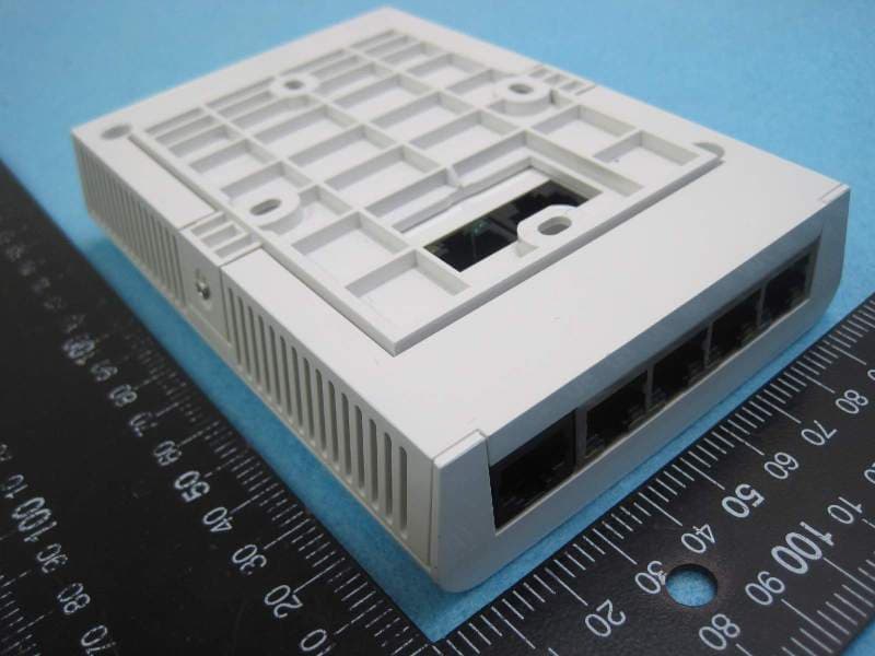
Click to zoom
Application Details
- Equipment Class
- DTS - Digital Transmission System
- Date of Grant
- Feb 06, 2014
- Application Purpose
- Original Equipment
- Date of Application
- Feb 06, 2014
- Equipment Note
- ProSAFE 802.11n Wall Mount Wireless Access Point
- Frequency Range
- 2422.00000000 - 2452.00000000
- Company
- Netgear Incorporated
- Country
- United States
Documents & Files
Document Text
Text extracted from the exhibit documents filed with the FCC. Open a document above to read the original.
Users Manual
Installation Guide ProSafe® Wall Mount Access Point WN370 Package Contents Unpack the box and verify the contents: •ProSafe® Wall Mount Access Point WN370 •Mounting bracket with four mounting screws •Punch down RJ45 connector •Warranty card •Software license agreement •Regulatory flyer •Installation Guide Installation Requirements You must have the following items to successfully install your access point: •A 6mm Phillips screwdriver •A T8 screwdriver •A computer running Windows XP or Windows 7 •A Standard EU or US wall outlet junction box with an ethernet cable routed through the wall from your LAN to the junction box •An IEEE 802.3af/at compliant PoE switch or !EEE 802.3af/at compliant PoE injector Mount the Access Point The access point requires an electrical outlet junction box mounted in a wall. To mount the access point to the wall: 1.Remove the faceplate from the outlet junction box. 2.Run the Ethernet cable through the junction box with enough slack to reach the access point. 3.Run the Ethernet cables through the mounting bracket. 4.Align the mounting bracket with the holes on the junction box. 5.Attach the mounting bracket to the junction box using the included Phillips head screws. 6.Connect the Ethernet cable providing PoE and network connectivity to the PoE port on the back of the access point. Note: If the Ethernet cable does not have a standard RJ45 connector, use the included RJ45 punch down connector to connect the Ethernet cable. 7.(Optional) Connect the Ethernet cable providing pass through support to the pass through port on the back of the access point. 8.Mount the access point to the mounting bracket using the included T8 screws. Set Up the Access Point The WN370 access point can only be deployed in a network managed by a ProSAFE WC7600 wireless controller. If you have a DHCP server in your network, option 43 must be enabled pointing towards the IP address of the WC7600. To discover and configure the access point using the WC7600 wireless controller: 1.Access the wireless controller at the network IP address that you configured. 2.Select Access Point > Discovery > Discovery Wizard. December 2013 NETGEAR, the NETGEAR logo, and Connect with Innovation are trademarks and/or registered trademarks of NETGEAR, Inc. and/or its subsidiaries in the United States and/or other countries. Information is subject to change without notice. © NETGEAR, Inc. All rights reserved. For indoor use only. Valid in all EU member states, EFTA states, and Switzerland. NETGEAR, Inc. 350 East Plumeria Drive San Jose, CA 95134 USA 3.Follow the steps onscreen to discover the access point and review the discovery results. 4.Select Access Point > Discovery > Managed AP List. Add the access points that you want to be managed by the wireless controller to the Managed AP List. Note: For extensive information about the Discovery Wizard and the discovery process, see the WC7600 reference manual. Verify Wireless Connectivity Using a computer with an 802.11b/g/n wireless adapter, verify connectivity by using a browser to connect to the Internet, or check for file and printer access on your network. You can also check the access point LEDs to verify a successful installation and connection. LEDDescription PowerSolid amber. The access point is booting. Slow blinking amber. The access point is not managed by a wireless controller. Green.The access point has successfully booted and is managed by a wireless controller. Note: If you cannot connect, see Troubleshooting Tips in this guide. Troubleshooting Tips Here are some tips for correcting simple problems you might have. The WC7600 Cannot Discover or Manage the Access Point If the WC7600 cannot discover or manage the access point, you can log in to the access point to troubleshoot and download the system log. NETGEAR support will use the system log to help diagnose any problems with the access point. Note: The WN370 has DHCP enabled by default and receives an IP address if you have a DHCP server in your network. If you have a DHCP server in your network, use the address assigned to the WN370 to log in to the access point. To log in to the access point and download the system log: 1.Configure a computer with the following IP options: •IP address. 192.168.0.22 •Subnet mask. 255.255.255.0 •Default gateway. 192.168.0.1 2.Enter http://192.168.0.160 or your access point’s assigned IP address into a browser. 3.Log in to the access point using the following default credentials: •ID. admin •Password. password. ActiveBlinking Green. There is network traffic through the access point. Off. There is not network traffic through the access point. WiFi On/OffSolid Green. The access point’s WiFi is active. Off. The access point’s WiFi is off. LEDDescription 4.Click Monitoring > Logs. 5.Click the Save As button. 6.Send the log to NETGEAR support. The Power LED is Solid Amber After Five Minutes There has been a boot up error and the access point needs to be reset. To reset the access point: 1.Remove the access point from the wall without disconnecting the Ethernet cable. 2.Press the reset button on the back of the access point for at least five seconds. 3.Mount the access point to the wall. 4.Follow the procedure for discovering the access point. Support Thank you for selecting NETGEAR products. After installing your device, locate the serial number on the label of your product and use it to register your product at https://my.netgear.com. You must register your product before you can use NETGEAR telephone support. NETGEAR recommends registering your product through the NETGEAR website. For product updates and web support, visit http://support.netgear.com. NETGEAR recommends that you use only the official NETGEAR support resources. For the current EU Declaration of Conformity, visit http://support.netgear.com/app/answers/detail/a_id/11621/. For regulatory compliance information, visit http://www.netgear.com/about/ regulatory/.
Users Manual
Notification of Compliance Regulatory Compliance Information This document includes user requirements for operating NETGEAR products in accordance with national laws including usage of radio spectrum and operation of radio devices. Failure of the end-user to comply with the applicable requirements may result in unlawful operation and adverse action against the end-user by the applicable national regulatory authority. The NETGEAR product firmware limits operation to only the channels allowed in a particular region or country. Therefore, all options described in this document may not be available in your version of the product. This document applies to both Class A and Class B devices: Class A devices are intended to be used in a commercial or industrial environment. They are not intended to be used in a residential home or be available for general public use. Class B devices are intended to be used in a residential setting, and may also be used in commercial and industrial applications. Examples of Class B devices are telephones, personal computers, and residential data gateways. Europe – EU Declaration of Conformity This section applies to products bearing the CE or CE! mark: Products bearing the CE or CE! mark comply with the following EU directives: EMC Directive 2004/108/EC Low Voltage Directive 2006/95/EC Ecodesign Directive 2009/125/EC RoHS Directive 2011/65/EU If the product has telecommunications functionality, it also complies with the requirement of the following EU directive: R&TTE Directive 1999/5/EC Compliance with these directives implies conformity to harmonized European standards that are noted in the EU Declaration of Conformity. The EU CE Declaration of Conformity may be found at http://support.netgear.com/app/answers/detail/a_id/11621/. Caution for installing this equipment outdoors: (Valid in all EU member states, EFTA states, and Switzerland.) Be aware that outdoor installations require special attention and will only be handled by trained and qualified installation personnel. No one from the general public is permitted to install NETGEAR wireless products outdoors when external antennas, power and grounding must be installed for use. Particular attention has to be given allowed operational frequencies. Contact NETGEAR for instructions on how to contact an installer for outdoor operations if this product requires the special considerations for outdoor installations. For detailed information concerning installations in France, the user should contact the national spectrum authority in France (http://www.arcep.fr/ ) The following paragraphs apply to WN2500RP: This device is a 2.4GHz and 5GHz wideband transmission system (transceiver), intended for indoor use only in all EU member states, EFTA states, and Switzerland. In Italy the end-user should apply for a license at the national spectrum authorities in order to obtain authorization to use the device for setting up outdoor radio links and/or for aupplying public access to telecommunications and/or network services. This device may not be used for setting up outdoor radio links in France and in some areas the RF output power may be limited to 10mW EIRP in the frequency range of 2454-2483.5 MHz. For detailed information the end-user should contact the national spectrum authority in France. Warning NETGEAR Class A products that may be utilized in domestic/residential environments may cause radio interference in which case the user may be required to take adequate measures. FCC Requirements for Operation in the United States Information in this section applies to products bearing the FCC mark (or statement): FCC Information to User This NETGEAR product does not contain any user serviceable components and is to be used with approved antennas only. Any product changes or modifications will invalidate all applicable regulatory certifications and approvals. The following statement applies to these products: EX6100 EX6200 VEGN2200 WN370 WN2500RP WN3000RPv2 WN3500RP This device and its antenna(s) must not be co-located or operating in conjunction with any other antenna or transmitter except in accordance with FCC multi-transmitter product procedures. FCC Guidelines for Human Exposure This NETGEAR product complies with FCC radiation exposure limits set forth for an uncontrolled environment. The equipment should be installed and operated with minimum distance of 20 cm between the radiator and your body. FCC Declaration of Conformity We, NETGEAR, Inc., 350 East Plumeria Drive, San Jose, CA 95134, declare under our sole responsibility that this product complies with Part 15 Subpart B of FCC CFR47 Rules. Operation is subject to the following two conditions: The device may not cause harmful interference, and The device must accept any interference received, including interference that may cause undesired operation. FCC Radio Frequency Interference Warnings & Instructions The NETGEAR product has been tested and found to comply with the limits for a Class B digital device, pursuant to Part 15 of the FCC Rules. These limits are designed to provide reasonable protection against harmful interference in a residential installation. This equipment uses and can radiate radio frequency energy and, if not installed and used in accordance with the instructions, may cause harmful interference to radio communications. However, there is no guarantee that interference will not occur in a particular installation. If this equipment does cause harmful interference to radio or television reception, which can be determined by turning the equipment off and on, the user is encouraged to try to correct the interference by one or more of the following methods: Reorient or relocate the receiving antenna. Increase the separation between the equipment and the receiver. Connect the equipment into an electrical outlet on a circuit different from that which the radio receiver is connected. Consult the dealer or an experienced…
Text truncated - open the document above for the full version.
Cover Letter(s)
Page No. : 1 NETGEAR, Inc. 350 East Plumeria Drive, San Jose, California 95134, USA Tel: 408-890-3657 / Fax: 408-907-8097 Confidential Letter Date: 2014/1/29 Federal Communications Commission Office of Engineering and Technology Equipment Authorization Division 7345 Oakland Mills Road Columbia, Maryland 21046 Subject: Confidentiality Request for FCC ID:PY313400245 Gentlemen: The form 731 and application have been electronically submitted and any attachments will be up loaded to your web site to be used in obtaining a grant of certification. Short-term Pursuant to DA 04-1705 of the Commission’s pubic notice, we request short-term confidential treatment for the following information until 180 days after the Grant Date of Equipment Authorization in order to ensure sensitive business information remains confidential until the actual marketing of the device: 1. External Photos 2. Internal Photos 3. Test Setup photos 4. User’s Manual Permanent NETGEAR, Inc. requests that the material in the following files be withheld from public disclosure in accordance with Section 0.457 of the Commission’s Rules, 47 C.F.R. 0.459, following grant of the application. 1. Block Diagram 2. Circuit Diagram 3. Operational Description 4. BOM list Should you require any further information, please contact the undersigned. Thank you for your consideration in this matter. Note: The registered grantee contact is not available, David Kay is signing for grantee contact. He/She can be reached at email: [email protected]. Sincerely, Applicant’s company name : NETGEAR, Inc. Applicant’s company address : 350 East Plumeria Drive, San Jose, California 95134, USA Signature : Signed for John Ramones Name and Job Title : John Ramones / Director of Product Design E-Mail : [email protected] Tel. : 408-890-3657
Cover Letter(s)
Netgear Inc. 350 East Plumeria Drive San Jose, CA 95134 U.S.A. Date: 2014/1/21 Power of Attorney To whom it may concern: I, the undersigned, John Ramones , hereby authorize the person listed below to act in behalf of me to sign all related documents for Netgear’s FCC application. Name: David Kay / Regulatory Compliance Manager Tel: +1 408 890 3657 E-mail: [email protected] Sincerely, Applicant : NETGEAR, Inc. Address : 350 East Plumeria Drive, San Jose, California 95134, USA Signature : _________________________________ Name and Job Title. : John Ramones / Director of Product Design and Regulations E-mail : [email protected] Te l . : 408-890-3657
Cover Letter(s)
Page No. :1 NETGEAR, Inc. 350 East Plumeria Drive, San Jose, California 95134, USA Tel: 408-890-3657 / Fax: 408-907-8097 Power of Attorney Date: 2013/12/26 Dear Sir, I hereby have entrusted the following person to be a proxy regarding application for Type Certification. Sporton International Inc. Address : No.8, Lane 724, Bo-ai St., Jhubei City, HsinChu County 302, Taiwan, R.O.C. Name : Leo Huang Job Title : Manager e-mail : [email protected] I am therefore responsible for the contents of the application. Brand name and model type of the specified radio equipment: NETGEAR / WN370 FCC ID: PY313400245 Product name: ProSAFE 802.11n Wall Mount Wireless Access Point Note: The registered grantee contact is not available, David Kay is signing for grantee contact. He/She can be reached at email: [email protected]. FCC Grantee contact person information. Applicant’s company name : NETGEAR, Inc. Applicant’s company address : 350 East Plumeria Drive, San Jose, California 95134, USA Signature : Signed for John Ramones Name and Job Title : John Ramones / Director of Product Design E-Mail : [email protected] Tel. : 408-890-3657
External Photos
Report No.: 3N2048 SPORTON International Inc. PAGE NUMBER : 1 OF 3 TEL : 886-3-327-3456 ISSUED DATE : Jan. 23, 2014 FAX : 886-3-327-0973 Photographs of EUT Report No.: 3N2048 SPORTON International Inc. PAGE NUMBER : 2 OF 3 TEL : 886-3-327-3456 ISSUED DATE : Jan. 23, 2014 FAX : 886-3-327-0973 Report No.: 3N2048 SPORTON International Inc. PAGE NUMBER : 3 OF 3 TEL : 886-3-327-3456 ISSUED DATE : Jan. 23, 2014 FAX : 886-3-327-0973
ID Label/Location Info
Label size: 6.3 x 6.5 cm
Internal Photos
Report No.: 3N2048 SPORTON International Inc. PAGE NUMBER : 1 OF 7 TEL : 886-3-327-3456 ISSUED DATE : Jan. 23, 2014 FAX : 886-3-327-0973 Photographs of EUT Report No.: 3N2048 SPORTON International Inc. PAGE NUMBER : 2 OF 7 TEL : 886-3-327-3456 ISSUED DATE : Jan. 23, 2014 FAX : 886-3-327-0973 Report No.: 3N2048 SPORTON International Inc. PAGE NUMBER : 3 OF 7 TEL : 886-3-327-3456 ISSUED DATE : Jan. 23, 2014 FAX : 886-3-327-0973 Report No.: 3N2048 SPORTON International Inc. PAGE NUMBER : 4 OF 7 TEL : 886-3-327-3456 ISSUED DATE : Jan. 23, 2014 FAX : 886-3-327-0973 Report No.: 3N2048 SPORTON International Inc. PAGE NUMBER : 5 OF 7 TEL : 886-3-327-3456 ISSUED DATE : Jan. 23, 2014 FAX : 886-3-327-0973 Report No.: 3N2048 SPORTON International Inc. PAGE NUMBER : 6 OF 7 TEL : 886-3-327-3456 ISSUED DATE : Jan. 23, 2014 FAX : 886-3-327-0973 Report No.: 3N2048 SPORTON International Inc. PAGE NUMBER : 7 OF 7 TEL : 886-3-327-3456 ISSUED DATE : Jan. 23, 2014 FAX : 886-3-327-0973
RF Exposure Info
Report No.: FR3N2048 FCC ID: PY313400245 Page No. : B1 of B3 Appendix B. Maximum Permissible Exposure Report No.: FR3N2048 FCC ID: PY313400245 Page No. : B2 of B3 1. Maximum Permissible Exposure 1.1. Applicable Standard Systems operating under the provisions of this section shall be operated in a manner that ensures that the public is not exposed to radio frequency energy levels in excess limit for maximum permissible exposure. In accordance with 47 CFR FCC Part 2 Subpart J, section 2.1091 this device has been defined as a mobile device whereby a distance of 0.2 m normally can be maintained between the user and the device. (A) Limits for Occupational / Controlled Exposure Frequency Range (MHz) Electric Field Strength (E) (V/m) Magnetic Field Strength (H) (A/m) Power Density (S) (mW/ cm²) Averaging Time |E|²,|H|² or S (minutes) 0.3-3.0 614 1.63 (100)* 6 3.0-30 1842 / f 4.89 / f (900 / f)* 6 30-300 61.4 0.163 1.0 6 300-1500 F/300 6 1500-100,000 5 6 (B) Limits for General Population / Uncontrolled Exposure Frequency Range (MHz) Electric Field Strength (E) (V/m) Magnetic Field Strength (H) (A/m) Power Density (S) (mW/ cm²) Averaging Time |E|²,|H|² or S (minutes) 0.3-1.34 614 1.63 (100)* 30 1.34-30 824/f 2.19/f (180/f)* 30 30-300 27.5 0.073 0.2 30 300-1500 F/1500 30 1500-100,000 1.0 30 Note: f = frequency in MHz ; *Plane-wave equivalent power density 1.2. MPE Calculation Method E (V/m) = d GP30 Power Density: Pd (W/m²) = 377 2 E E = Electric field (V/m) P = Average RF output power (W) G = EUT Antenna numeric gain (numeric) d = Separation distance between radiator and human body (m) The formula can be changed to Pd = 2 377 30 d GP From the EUT RF output power, the minimum mobile separation distance, d=0.2m, as well as the gain of the used antenna, the RF power density can be obtained. Report No.: FR3N2048 FCC ID: PY313400245 Page No. : B3 of B3 1.3. Calculated Result and Limit Antenna Type : Printed Antenna Max Conducted Power for IEEE 802.11g: 25.91 dBm Antenna Gain (dBi) Antenna Gain (numeric) Average Output Power (dBm) Average Output Power (mW) Power Density (S) (mW/cm²) Limit of Power Density (S) (mW/cm²) Test Result 3.00 1.9953 25.9084 389.8014 0.154808 1 Complies
Test Report
SPORTON International Inc. No. 52, Hwa Ya 1st Rd., Hwa Ya Technology Park, Kwei-Shan Hsiang, Tao Yuan Hsien, Taiwan, R.O.C. Ph: 886-3-327-3456 / FAX: 886-3-327-0973 / www.sporton.com.tw Report Format Version: 01 FCC RADIO TEST REPORT Applicant’s company NETGEAR, Inc. Applicant Address 350 East Plumeria Drive, San Jose, California 95134, USA FCC ID PY313400245 Product Name ProSAFE 802.11n Wall Mount Wireless Access Point Brand Name NETGEAR Model No. WN370 Test Rule 47 CFR FCC Part 15 Subpart C § 15.247 Test Freq. Range 2400 ~ 2483.5MHz Received Date Nov. 22, 2013 Final Test Date Jan. 05, 2014 Submission Type Original Equipment Statement Test result included in this report is for the IEEE 802.11n and IEEE 802.11b/g part of the product. The test result in this report refers exclusively to the presented test model / sample. Without written approval of SPORTON International Inc., the test report shall not be reproduced except in full. The measurements and test results shown in this test report were made in accordance with the procedures and found in compliance with the limit given in ANSI C63.10-2009, 47 CFR FCC Part 15 Subpart C, KDB 558074 D01 v03r01 and KDB 662911 D01 v02. The test equipment used to perform the test is calibrated and traceable to NML/ROC. Report No.: FR3N2048 Report Format Version: 01 Page No. : i of ii FCC ID: PY313400245 Issued Date : Jan. 23, 2014 Table of Contents 1. CERTIFICATE OF COMPLIANCE ......................................................................................................................... 1 2. SUMMARY OF THE TEST RESULT .......................................................................................................................... 2 3. GENERAL INFORMATION .................................................................................................................................. 3 3.1. Product Details....................................................................................................................................................................................3 3.2. Accessories .........................................................................................................................................................................................4 3.3. Table for Filed Antenna.......................................................................................................................................................................5 3.4. Table for Carrier Frequencies .............................................................................................................................................................5 3.5. Table for Test Modes ...........................................................................................................................................................................6 3.6. Table for Testing Locations..................................................................................................................................................................7 3.7. Table for Supporting Units ...................................................................................................................................................................7 3.8. Table for Parameters of Test Software Setting .....................................................................................................................................8 3.9. EUT Operation during Test ...................................................................................................................................................................8 3.10. Duty Cycle ..........................................................................................................................................................................................9 3.11. Test Configurations ...........................................................................................................................................................................11 4. TEST RESULT ................................................................................................................................................... 14 4.1. AC Power Line Conducted Emissions Measurement.........................................................................................................................14 4.2. Maximum Conducted Output Power Measurement .........................................................................................................................18 4.3. Power Spectral Density Measurement ..............................................................................................................................................21 4.4. 6dB Spectrum Bandwidth Measurement ..........................................................................................................................................29 4.5. Radiated Emissions Measurement ....................................................................................................................................................34 4.6. Emissions Measurement ....................................................................................................................................................................52 4.7. Antenna Requirements .....................................................................................................................................................................70 5. LIST OF MEASURING EQUIPMENTS ................................................................................................................... 71 6. MEASUREMENT UNCERTAINTY.......................................................................................................................... 73 APPENDIX A. TEST PHOTOS ........................................................................................................................ A1 ~ A5 APPENDIX B. MAXIMUM PERMISSIBLE EXPOSURE ....…
Text truncated - open the document above for the full version.
Test Setup Photos
Report No.: FR3N2048 FCC ID: PY313400245 Page No. : A1 of A5 Appendix A. Test Photos Report No.: FR3N2048 FCC ID: PY313400245 Page No. : A2 of A5 1. Photographs of Conducted Emissions Test Configuration FRONT VIEW REAR VIEW Report No.: FR3N2048 FCC ID: PY313400245 Page No. : A3 of A5 2. Photographs of Radiated Emissions Test Configuration Test Configuration: 9kHz ~30MHz FRONT VIEW REAR VIEW Report No.: FR3N2048 FCC ID: PY313400245 Page No. : A4 of A5 Test Configuration: 30MHz~1GHz FRONT VIEW REAR VIEW Report No.: FR3N2048 FCC ID: PY313400245 Page No. : A5 of A5 Test Configuration: Above 1GHz FRONT VIEW REAR VIEW
Contact Information
Applicant
David Kay
Test Firm
SPORTON International Inc.Leo Huang
Technical Specifications
| # | Rule Parts | Frequency Range | Power Output |
|---|---|---|---|
| 2 | 15C | 2.42 GHz - 2.45 GHz | 126.20 mW |
Other Applications from Netgear Incorporated

PY325100647
Aug 04, 2026BE5000 Dual-Band PoE 2.5G Insight Managed WiFi 7 Outdoor Access Point
Equipment Class
DTS - Digital Transmission SystemPY325300652
May 12, 2026BE5000 Dual-Band PoE 2.5G Insight Managed WiFi 7 Access Point
Equipment Class
NII - Unlicensed National Information Infrastructure TXPY325400656
Apr 16, 2026Orbi Outdoor Satellite
Equipment Class
DTS - Digital Transmission SystemPY324400640
Dec 12, 2025Orbi 11BE WiFi 7 Tri-band Router, Orbi 11BE WiFi 7 Tri-band Satellite
Equipment Class
NII - Unlicensed National Information Infrastructure TXPY324100618
Jul 31, 2024Nighthawk 5G Mobile Router
Equipment Class
PCB - PCS Licensed Transmitter