PY314200260Wireless Cable Data Gateway
Netgear Incorporated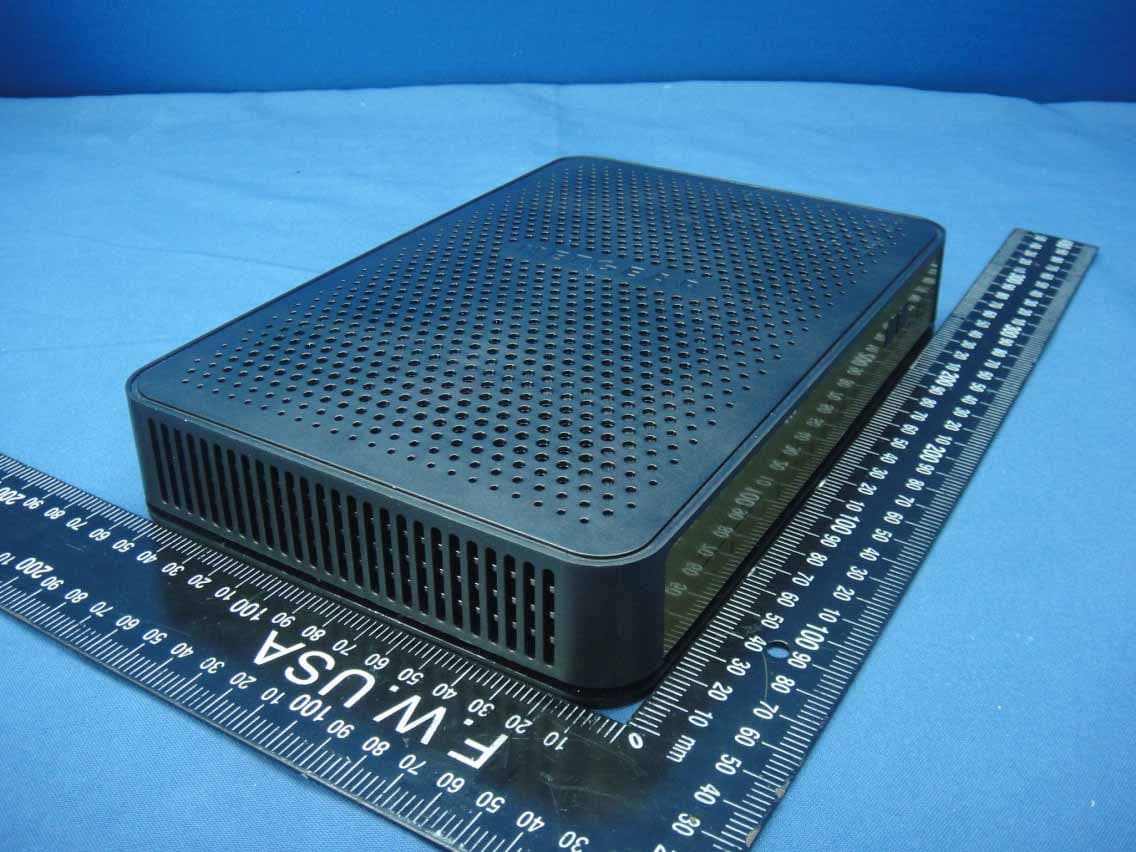
Click to zoom
Application Details
- Equipment Class
- DTS - Digital Transmission System
- Date of Grant
- Nov 11, 2014
- Application Purpose
- Original Equipment
- Date of Application
- Nov 10, 2014
- Equipment Note
- Wireless Cable Data Gateway
- Frequency Range
- 5745.00000000 - 5825.00000000
- Company
- Netgear Incorporated
- Country
- United States
Documents & Files
Document Text
Text extracted from the exhibit documents filed with the FCC. Open a document above to read the original.
Users Manual
Notification of Compliance Regulatory Compliance Information This document includes user requirements for operating NETGEAR products in accordance with national laws including usage of radio spectrum and operation of radio devices. Failure of the end-user to comply with the applicable requirements may result in unlawful operation and adverse action against the end-user by the applicable national regulatory authority. The NETGEAR product firmware limits operation to only the channels allowed in a particular region or country. Therefore, all options described in this document may not be available in your version of the product. This document applies to both Class A and Class B devices: Class A devices are intended to be used in a commercial or industrial environment. They are not intended to be used in a residential home or be available for general public use. Class B devices are intended to be used in a residential setting, and may also be used in commercial and industrial applications. Examples of Class B devices are telephones, personal computers, and residential data gateways. Fuses should only be installed by service personnel. NETGEAR recommends the use of 26 AWG or larger gauge phone line cords. Europe – EU Declaration of Conformity This section applies to products bearing the CE or CE! mark: Products bearing the CE or CE! mark comply with the following EU directives: EMC Directive 2004/108/EC Low Voltage Directive 2006/95/EC Ecodesign Directive 2009/125/EC RoHS Directive 2011/65/EU If the product has telecommunications functionality, it also complies with the requirement of the following EU directive: R&TTE Directive 1999/5/EC Compliance with these directives implies conformity to harmonized European standards that are noted in the EU Declaration of Conformity. The EU CE Declaration of Conformity may be found at http://support.netgear.com/app/answers/detail/a_id/11621/. Caution for installing this equipment outdoors: (Valid in all EU member states, EFTA states, and Switzerland.) Be aware that outdoor installations require special attention and will only be handled by trained and qualified installation personnel. No one from the general public is permitted to install NETGEAR wireless products outdoors when external antennas, power and grounding must be installed for use. Particular attention has to be given allowed operational frequencies. Contact NETGEAR for instructions on how to contact an installer for outdoor operations if this product requires the special considerations for outdoor installations. For detailed iformation concerning installations in France, the user should contact the national spectrum authority in France (http://www.arcep.fr/ ) The following paragraphs apply to WN2500RP: This device is a 2.4GHz and 5GHz wideband transmission system (transceiver), intended for indoor use only in all EU member states, EFTA states, and Switzerland. In Italy the end-user should apply for a license at the national spectrum authorities in order to obtain authorization to use the device for setting up outdoor radio links and/or for applying public access to telecommunications and/or network services. This device may not be used for setting up outdoor radio links in France and in some areas the RF output power may be limited to 10mW EIRP in the frequency range of 2454-2483.5 MHz. For detailed information the end-user should contact the national spectrum authority in France. Warning NETGEAR Class A products that may be utilized in domestic/residential environments may cause radio interference in which case the user may be required to take adequate measures. FCC Requirements for Operation in the United States Information in this section applies to products bearing the FCC mark (or statement): FCC Information to User This NETGEAR product does not contain any user serviceable components and is to be used with approved antennas only. Any product changes or modifications will invalidate all applicable regulatory certifications and approvals. The following statement applies to these products: C6300 JWNR2000v5 WN2500RP WNR618 D6200V2 JWNR2010v5 WN3000RPv2 EX2700 R6050 WN3500RP EX6100 R7500 WNDR3400v3 EX6200 R8000 WN1000v4 HMNC100 STS7000 WNR2010 JNR1010v2 VEGN2200 WNR2020 JR6150 WN370 WNR614 FCC Guidelines for Human Exposure The NETGEAR product complies with FCC radiation exposure limits set forth for an uncontrolled environment. The equipment should be installed and operated with minimum distance of 20cm between the radiator and your body. The following statement applies to this product: C6300XB3C6300BD This product complies with FCC radiation exposure limits set forth for an uncontrolled environment. The device should be installed and operated with minimum distance of 25cm 35cm between the radiator and your body. The following statement applies to this product: R8000 This product complies with FCC radiation exposure limits set forth for an uncontrolled environment. The device should be installed and operated with minimum distance of 30cm between the radiator and your body. FCC Declaration of Conformity We, NETGEAR, Inc., 350 East Plumeria Drive, San Jose, CA 95134, declare under our sole responsibility that this product complies with Part 15 Subpart B of FCC CFR47 Rules. Operation is subject to the following two conditions: The device may not cause harmful interference, and The device must accept any interference received, including interference that may cause undesired operation. FCC Radio Frequency Interference Warnings & Instructions The NETGEAR product has been tested and found to comply with the limits for a Class B digital device, pursuant to Part 15 of the FCC Rules. These limits are designed to provide reasonable protection against harmful interference in a residential installation. This equipment uses and can radiate radio frequency energy and, if not installed and used in accordance with the instructions, m…
Text truncated - open the document above for the full version.
Users Manual
350 East Plumeria Drive San Jose, CA 95134 USA September 2014 202-11434-01 AC1900, N900, and N450 WiFi Cable Data Gateways Models C6300BD, CG4500BD, and CG3000Dv2 User Manual 2 AC1900, N900, and N450 WiFi Cable Data Gateways Support Thank you for selecting NETGEAR products. For technical support, contact Cox Support. Compliance For regulatory compliance information, visit http://www.netgear.com/about/regulatory. See the regulatory compliance document before connecting the power supply. Trademarks NETGEAR, the NETGEAR logo, and Connect with Innovation are trademarks and/or registered trademarks of NETGEAR, Inc. and/or its subsidiaries in the United States and/or other countries. Information is subject to change without notice. © NETGEAR, Inc. All rights reserved. Revision History Publication Part NumberPublish DateComments 202-11434-01September 2014First publication 3 Contents Chapter 1 Hardware Overview Introduction . . . . . . . . . . . . . . . . . . . . . . . . . . . . . . . . . . . . . . . . . . . . . . . . . . . . . . . . . 8 Hardware Features of the AC1900 WiFi Cable Data Gateway. . . . . . . . . . . . . . . 8 Front Panel of the AC1900 WiFi Cable Data Gateway . . . . . . . . . . . . . . . . . . . 8 Back Panel of the AC1900 WiFi Cable Data Gateway . . . . . . . . . . . . . . . . . . 11 Product Label of the AC1900 WiFi Cable Data Gateway . . . . . . . . . . . . . . . . 12 Hardware Features of the N900 WiFi Cable Data Gateway . . . . . . . . . . . . . . . . 12 Front Panel of the N900 WiFi Cable Data Gateway . . . . . . . . . . . . . . . . . . . . 12 Back Panel of the N900 WiFi Cable Data Gateway . . . . . . . . . . . . . . . . . . . . . 15 Product Label of the N900 WiFi Cable Data Gateway . . . . . . . . . . . . . . . . . . 16 Hardware Features of the N450 WiFi Cable Data Gateway . . . . . . . . . . . . . . . . 16 Front Panel of the N450 WiFi Cable Data Gateway . . . . . . . . . . . . . . . . . . . . 16 Back Panel of the N450 WiFi Cable Data Gateway . . . . . . . . . . . . . . . . . . . . . 19 Product Label of the N450 WiFi Cable Data Gateway . . . . . . . . . . . . . . . . . . 20 Position Your WiFi Cable Data Gateway . . . . . . . . . . . . . . . . . . . . . . . . . . . . . . . . . 20 Chapter 2 Connect and Get Started WiFi Cable Data Gateway Setup Requirements . . . . . . . . . . . . . . . . . . . . . . . . . . 23 Use Standard TCP/IP Properties for DHCP . . . . . . . . . . . . . . . . . . . . . . . . . . . . 23 WiFi Devices and Security Settings . . . . . . . . . . . . . . . . . . . . . . . . . . . . . . . . . . 23 Types of Logins and Access . . . . . . . . . . . . . . . . . . . . . . . . . . . . . . . . . . . . . . . . . . . 23 Access NETGEAR genie . . . . . . . . . . . . . . . . . . . . . . . . . . . . . . . . . . . . . . . . . . . . . . . 23 Change the Password . . . . . . . . . . . . . . . . . . . . . . . . . . . . . . . . . . . . . . . . . . . . . . . . 25 Join the WiFi Network of the WiFi Cable Data Gateway . . . . . . . . . . . . . . . . . . . 26 Manual Method . . . . . . . . . . . . . . . . . . . . . . . . . . . . . . . . . . . . . . . . . . . . . . . . . . . 26 Wi-Fi Protected Setup Method . . . . . . . . . . . . . . . . . . . . . . . . . . . . . . . . . . . . . . . . 27 Chapter 3 Configure Parental Controls and Basic WiFi Settings Set Up Parental Controls . . . . . . . . . . . . . . . . . . . . . . . . . . . . . . . . . . . . . . . . . . . . . 29 View or Change the Basic Settings for the Main WiFi Network . . . . . . . . . . . . . 31 Enable and Configure the Guest WiFi Network. . . . . . . . . . . . . . . . . . . . . . . . . . . 36 Chapter 4 Manage Internet, WAN, and LAN Settings and Use the WPS Wizard Manage the Internet Setup . . . . . . . . . . . . . . . . . . . . . . . . . . . . . . . . . . . . . . . . . . . 42 Manage the WAN Settings . . . . . . . . . . . . . . . . . . . . . . . . . . . . . . . . . . . . . . . . . . . . 43 View or Change the WAN Settings . . . . . . . . . . . . . . . . . . . . . . . . . . . . . . . . . . . 43 Configure a Default DMZ Server . . . . . . . . . . . . . . . . . . . . . . . . . . . . . . . . . . . . 45 4 AC1900, N900, and N450 WiFi Cable Data Gateways Manage the LAN Settings . . . . . . . . . . . . . . . . . . . . . . . . . . . . . . . . . . . . . . . . . . . . 46 View or Change the LAN Settings . . . . . . . . . . . . . . . . . . . . . . . . . . . . . . . . . . . 47 Use the WiFi Cable Data Gateway as a DHCP Server . . . . . . . . . . . . . . . . . . . 48 Manage IP Address Reservation . . . . . . . . . . . . . . . . . . . . . . . . . . . . . . . . . . . . . 49 Use the WPS Wizard to Add a Device to the WiFi Network . . . . . . . . . . . . . . . . 52 Use WPS with the Push Button Method . . . . . . . . . . . . . . . . . . . . . . . . . . . . . . 53 Use WPS with the PIN Method . . . . . . . . . . . . . . . . . . . . . . . . . . . . . . . . . . . . . . 55 Chapter 5 Manage the Firewall and Secure Your Network Block Keywords and Domains for HTTP Traffic . . . . . . . . . . . . . . . . . . . . . . . . . . 59 Set Up Blocking . . . . . . . . . . . . . . . . . . . . . . . . . . . . . . . . . . . . . . . . . . . . . . . . . . . 59 Remove a Keyword or Domain from the Blocked List . . . . . . . . . . . . . . . . . . . 60 Remove All Keywords and Domains from the Blocked List . . . . . . . . . . . . . . 61 Specify a Trusted Computer . . . . . . . . . . . . . . . . . . . . . . . . . . . . . . . . . . . . . . . . 61 Block Access to Services and Applications . . . . . . . . . . . . . . . . . . . . . . . . . . . . . . 62 Block a Default Service . . . . . . . . . . . . . . . . . . . . . . . . . . . . . . . . . . . . . . . . . . . . 63 Add and Block a Custom Service . . . . . . . . . . . . . . . . . . . . . . . . . . . . . . . . . . . . 65 Change the Settings for a Blocked Service . . . . . . . . . . . . . . . . . . . . . . . . . . . . 67 Remove a Blocked Service. . . . . . . . . . . . . . . . . . . . . . . . . . . . . . . . . . . . . . . . . . 68 Schedule When Fe…
Text truncated - open the document above for the full version.
Attestation Statements
Netgear Incorporated 350 East Plumeria Drive San Jose California United States 95134 TEL: 408-890-3160 FAX: 408-907-8097 August 4, 2014 We, Netgear INC.declare that the device does not support channel 12 ~ 13 in 2.4GHz band and any non- US channels in all the operational mode(s) for the following product. FCC ID: PY314200260 If you should have any question(s) regarding this declaration, please don’t hesitate to contact us. Thank you! ----------------------------------- Name: David Kay / Title: Director of Product Design Netgear INC. Tel: 408-890-3160 Fax: 408-907-8097 E-mail: [email protected]
Cover Letter(s)
Netgear Incorporated 350 East Plumeria Drive San Jose California United States 95134 TEL: 408-890-3657 FAX: 408-907-8097 Date: 2014-09-05 FCC ID: PY314200260 To the attention of Federal Communications Commission Authorization and Evaluation Division Confidentiality Request Pursuant to Sections 0.457 and 0.459 of the Commission’s Rules, the Applicant hereby requests confidential treatment of information accompanying this Application as outlined below: Schematics Block Diagram Software Operating Description The above materials contain trade secrets and proprietary information not customarily released to the public. The public disclosure of these matters might be harmful to the Applicant and provide unjustified benefits to its competitors. The Applicant understands that pursuant to Rule 0.457, disclosure of this Application and all accompanying documentation will not be made before the date of the Grant for this application. Sincerely yours, ----------------------------------- Name: David Kay / Title: Regulatory Compliance Manager NETGEAR Inc. Tel: 408-890-3657 Fax: 408-907-8097 E-mail: [email protected]
Cover Letter(s)
NETGEAR INC. 2350 East Plumeria Drive, San Jose CA 96134, USA Tel: 408 890 3657 Fax: 408 907 8097 Date: 2014-09-29 FCC ID: PY314100252 A U T H O R I Z A T I O N L E T T E R To whom it may concern: We, the undersigned, hereby authorize Andrea Hsia / Senior Specialist of Bureau Veritas Consumer Products Services (H.K.) Ltd., Taoyuan Branch (BV CPS Taoyuan) of Taiwan to act on our behalf in all manners relating to FCC15C/E application for equipment authorization, including signing of all documents relating to these matters. Any and all acts carried out by Andrea Hsia / Senior Specialist of BV CPS Taoyuan on our behalf shall have the same effect as acts of our own. If you have any questions regarding the authorization, please don’t hesitate to contact us. Sincerely yours, ----------------------------------- Name: David Kay/ Title: Regulatory Compliance Manager Netgear INC. Tel: 408-890-3657 Fax: 408-907-8097 E-mail: [email protected]
External Photos
Report No.: 140710C17 Page 1 CONSTRUCTION PHOTOS OF EUT Report No.: 140710C17 Page 2 Report No.: 140710C17 Page 3 Model: AD898F20 Report No.: 140710C17 Page 4 Report No.: 140710C17 Page 5 Model: 2AAF042F Report No.: 140710C17 Page 6
ID Label/Location Info
Label Location
ID Label/Location Info
SHEET: AUTHOR:TITLE: P/N: REV: THIS DOCUMENT AND THE DATA DISCLOSED HEREIN OR WHEREWITH IS NOT TO BE REPRODUCED, USED OR DISCLOSED IN WHOLE OR IN PART TO ANYONE WITHOUT THE PERMISSION OF NETGEAR, INC. REV DESCRIPTION OF REVISION ENG APPDDATE 01AW-12905-011 of 1 AW,C6300BD-1CXNAS, PLBLR HU 07APR14R HUINITIAL DOCUMENT CREATION01 7 NOTE: 1. REFER TO NETGEAR SPEC. DOC-00093 FOR COLOR TOLERANCES. 2. INK COLOR IS SHOWN TO THE RIGHT. 3. DIE LINES ARE MAGENTA COLOR AND DO NOT PRINT. 4. MAC & SERIAL NUMBERS TO BE PRINTED BY THE ODM. 5. See NTGR DOC-00112 for SN standard. 6. NTGR SN and MAC address barcode to be encoded AIM USS Code39 and include printed characters below barcodes. 7. INSURE COUNTRY OF ORIGIN IS CORRECT. A. IF COUNTRY OF ORIGIN IS PRE-PRINTED, UNHIDE THE APPROPRIATE COUNTRY OF ORIGIN LAYER AND INCLUDE COUNTRY OF ORIGIN ON LABEL. B. IF COUNTRY OF ORIGIN IS POST-PRINTED USING A THERMAL PRINTER (OR EQUIVALENT), OMIT TEXT FROM ARTWORK (USE LAYERS). PANTONE 877C PANTONE BLACK C
Internal Photos
Report No.: 140710C17 Page 7 Report No.: 140710C17 Page 8 Report No.: 140710C17 Page 9 Report No.: 140710C17 Page 10 Report No.: 140710C17 Page 11 Report No.: 140710C17 Page 12 Report No.: 140710C17 Page 13 Report No.: 140710C17 Page 14 Report No.: 140710C17 Page 15
Operational Description
FCC ID: PY314200260 Report No.: RF140710C17 Operational Description This device is a Wireless Cable Data Gateway, which operates in 2.4GHz & 5.0GHz band; the maximum data rate could be up to 1 300Mbps which OFDM technique. If the signal to noise radio is too poor which could not support 1300Mbps, the 11Mbps data rate with DSSS technique will be applied. The transmitter of the EUT is powered by the 12Vdc. The EUT is used PCB antenna with IPEX connector. The other instruction, please have a look at the user’s manual. FCC 15.407(c) states: The device shall automatically discontinue transmission in case of either absence of information to transmit or operational failure. These provisions are not intended to preclude the transmission of control or signaling information or the use of repetitive codes used by certain digital technologies to complete frame or burst intervals. Applicants shall include in their application for equipment authorization a description of how this requirement is met” Data transmission is always initiated by software, which is then pass down through the MAC, through the digital and analog baseband, and finally to the RF chip. Several special packets (ACKs, CTS, PSPoll, etc...) are initiated by the MAC. There are the only ways the digital baseband portion will turn on the RF transmitter, which it then turns off at the end of the packet. Therefore, the transmitter will be on only while one of the aforementioned packets are being transmitted.
RF Exposure Info
Report No.: SA140710C17 1 of 9 Report Format Version 5.0.0 RF EXPOSURE REPORT REPORT NO.: SA140710C17 MODEL NO.: C6300BD FCC ID: PY314200260 RECEIVED: July 10, 2014 TESTED: July 29, 2014 ISSUED: Oct. 09, 2014 APPLICANT: Netgear Inc ADDRESS: 350 E. Plumeria Drive, San Jose CA 95134, USA ISSUED BY: Bureau Veritas Consumer Products Services (H.K.) Ltd., Taoyuan Branch Hsin Chu Laboratory LAB ADDRESS: No. 81-1, Lu Liao Keng, 9th Ling,Wu Lung Tsuen, Chiung Lin Hsiang, Hsin Chu Hsien 307, Taiwan, R.O.C. This report should not be used by the client to claim product certification, approval, or endorsement by any government agencies. This report is for your exclusive use. Any copying or replication of this report to or for any other person or entity, or use of our name or trademark, is permitted only with our prior written permission. This report sets forth our findings solely with respect to the test samples identified herein. The results set forth in this report are not indicative or representative of the quality or characteristics of the lot from which a test sample was taken or any similar or identical product unless specifically and expressly noted. Our report includes all of the tests requested by you and the results thereof based upon the information that you provided to us. You have 60 days from date of issuance of this report to notify us of any material error or omission caused by our negligence, provided, however, that such notice shall be in writing and shall specifically address the issue you wish to raise. A failure to raise such issue within the prescribed time shall constitute your unqualified acceptance of the completeness of this report, the tests conducted and the correctness of the report contents. Unless specific mention, the uncertainty of measurement has been explicitly taken into account to declare the compliance or non-compliance to the specification Report No.: SA140710C17 2 of 9 Report Format Version 5.0.0 TABLE OF CONTENTS RELEASE CONTROL RECORD ..................................................................................... 3 1. CERTIFICATION ...................................................................................................... 4 2. RF EXPOSURE LIMIT .............................................................................................. 5 3. MPE CALCULATION FORMULA ............................................................................. 5 4. CLASSIFICATION .................................................................................................... 5 5. ANTENNA GAIN....................................................................................................... 6 6. CALCULATION RESULT OF MAXIMUM CONDUCTED POWER ........................... 7 Report No.: SA140710C17 3 of 9 Report Format Version 5.0.0 RELEASE CONTROL RECORD ISSUE NO. REASON FOR CHANGE DATE ISSUED SA140710C17 Original release Oct. 09, 2014 Report No.: SA140710C17 5 of 9 Report Format Version 5.0.0 2. RF EXPOSURE LIMIT LIMITS FOR MAXIMUM PERMISSIBLE EXPOSURE (MPE) FREQUENCY RANGE (MHz) ELECTRIC FIELD STRENGTH (V/m) MAGNETIC FIELD STRENGTH (A/m) POWER DENSITY (mW/cm 2 ) AVERAGE TIME (minutes) LIMITS FOR GENERAL POPULATION / UNCONTROLLED EXPOSURE 300-1500 ... ... F/1500 30 1500-100,000 ... ... 1.0 30 F = Frequency in MHz 3. MPE CALCULATION FORMULA Pd = (Pout*G) / (4*pi*r 2 ) where Pd = power density in mW/cm 2 Pout = output power to antenna in mW G = gain of antenna in linear scale pi = 3.1416 r = distance between observation point and center of the radiator in cm 4. CLASSIFICATION The antenna of this product, under normal use condition, is at least 35cm away from the body of the user. So, this device is classified as Mobile Device. Report No.: SA140710C17 6 of 9 Report Format Version 5.0.0 5. ANTENNA GAIN The antennas provided to the EUT, please refer to the following table: For 2.4G used Ant. No. Transmitter Circuit Brand Model Antenna Type Antenna Gain (dBi) Connector type 1 CHAIN (0) MASTER WAVE 98P92UIPF030 PCB 2 I-PEX 2 CHAIN (1) 98P92UIPF031 2 3 CHAIN (2) 98P92UIPF033 2 For 5G used Ant. No. Transmitter Circuit Brand Model Antenna Type Antenna Gain (dBi) Connector type 4 CHAIN (0) MASTER WAVE 98P92UIPF033 PCB 2 I-PEX 5 CHAIN (1) 98P92UIPF034 2 6 CHAIN (2) 98P92UIPF034 2 Report No.: SA140710C17 7 of 9 Report Format Version 5.0.0 6. CALCULATION RESULT OF MAXIMUM CONDUCTED POWER For WLAN: 15.247(2.4GHz) 802.11b FREQUENCY (MHz) CONDUCTED POWER (mW) ANTENNA GAIN (dBi) DISTANCE (cm) POWER DENSITY (mW/cm 2 ) LIMIT (mW/cm 2 ) 2412 - 2462 683.701 6.77 35 0.21112 1.00 NOTE: Directional gain = 2dBi + 10log(3) = 6.77dBi. 802.11g FREQUENCY (MHz) CONDUCTED POWER (mW) ANTENNA GAIN (dBi) DISTANCE (cm) POWER DENSITY (mW/cm 2 ) LIMIT (mW/cm 2 ) 2412 - 2462 661.388 6.77 35 0.20423 1.00 NOTE: Directional gain = 2dBi + 10log(3) = 6.77dBi. 802.11n (HT20) FREQUENCY BAND (MHz) CONDUCTED POWER (mW) ANTENNA GAIN (dBi) DISTANCE (cm) POWER DENSITY (mW/cm 2 ) LIMIT (mW/cm 2 ) 2412 - 2462 476.954 6.77 35 0.14728 1.00 NOTE: Directional gain = 2dBi + 10log(3) = 6.77dBi. 802.11n (HT40) FREQUENCY (MHz) CONDUCTED POWER (mW) ANTENNA GAIN (dBi) DISTANCE (cm) POWER DENSITY (mW/cm 2 ) LIMIT (mW/cm 2 ) 2422 - 2452 200.838 6.77 35 0.06202 1.00 NOTE: Directional gain = 2dBi + 10log(3) = 6.77dBi. Report No.: SA140710C17 8 of 9 Report Format Version 5.0.0 For WLAN: 15.247(5GHz) 802.11a FREQUENCY (MHz) CONDUCTED POWER (mW) ANTENNA GAIN (dBi) DISTANCE (cm) POWER DENSITY (mW/cm 2 ) LIMIT (mW/cm 2 ) 5745 - 5825 829.037 6.77 35 0.25599 1.00 NOTE: Directional gain = 2dBi + 10log(3) = 6.77dBi. 802.11ac (VHT20) FREQUENCY (MHz) CONDUCTED POWER (mW) ANTENNA GAIN (dBi) DISTANCE (cm) POWER DENSITY (mW/cm 2 ) LIMIT (mW/cm 2 ) 5745 - 5825 831.402 6.77 35 0.25672 1.00 NOTE: Directional gain = 2dBi + 10log(3) = 6.77dBi. 802.11ac (VHT40) FREQUENCY (MHz) CONDUCTED POWER (mW) ANTENNA GAIN (dBi) DISTANCE (cm) POWER DENSITY (mW/cm 2 ) LIMIT (mW/cm 2 ) 5755 - 5795 814.961 6.77 35 0.25165 1.00 NOTE: Directional gain = 2dBi…
Text truncated - open the document above for the full version.
Test Report
Report No.: RF140710C17 R1 1 of 118 Report Format Version 5.2.1 Cancels and replaces the report No.: RF140710C17-1 dated Oct. 09, 2014 FCC TEST REPORT (15.247) REPORT NO.: RF140710C17 R1 MODEL NO.: C6300BD FCC ID: PY314200260 RECEIVED: July 10, 2014 TESTED: July 22 to 29, 2014 ISSUED: Oct. 15, 2014 APPLICANT: Netgear Inc ADDRESS: 350 E. Plumeria Drive, San Jose CA 95134, USA ISSUED BY: Bureau Veritas Consumer Products Services (H.K.) Ltd., Taoyuan Branch Hsin Chu Laboratory LAB ADDRESS : No. 81-1, Lu Liao Keng, 9th Ling, Wu Lung Tsuen, Chiung Lin Hsiang, Hsin Chu Hsien 307, Taiwan, R.O.C. TEST LOCATION (1): No. 81-1, Lu Liao Keng, 9th Ling, Wu Lung Tsuen, Chiung Lin Hsiang, Hsin Chu Hsien 307, Taiwan, R.O.C. TEST LOCATION (2): No. 49, Ln. 206, Wende Rd., Shangshan Tsuen, Chiung Lin Hsiang, Hsin Chu Hsien 307, Taiwan, R.O.C. This report should not be used by the client to claim product certification, approval, or endorsement by TAF or any government agencies. This report is for your exclusive use. Any copying or replication of this report to or for any other person or entity, or use of our name or trademark, is permitted only with our prior written permission. This report sets forth our findings solely with respect to the test samples identified herein. The results set forth in this report are not indicative or representative of the quality or characteristics of the lot from which a test sample was taken or any similar or identical product unless specifically and expressly noted. Our report includes all of the tests requested by you and the results thereof based upon the information that you provided to us. You have 60 days from date of issuance of this report to notify us of any material error or omission caused by our negligence, provided, however, that such notice shall be in writing and shall specifically address the issue you wish to raise. A failure to raise such issue within the prescribed time shall constitute your unqualified acceptance of the completeness of this report, the tests conducted and the correctness of the report contents. Unless specific mention, the uncertainty of measurement has been explicitly taken into account to declare the compliance or non-compliance to the specification Report No.: RF140710C17 R1 2 of 118 Report Format Version 5.2.1 Cancels and replaces the report No.: RF140710C17-1 dated Oct. 09, 2014 Table of Contents RELEASE CONTROL RECORD .......................................................................................... 5 1. CERTIFICATION ...................................................................................................... 6 2. SUMMARY OF TEST RESULTS .............................................................................. 7 2.1 MEASUREMENT UNCERTAINTY ........................................................................... 8 3. GENERAL INFORMATION ....................................................................................... 9 3.1 GENERAL DESCRIPTION OF EUT ......................................................................... 9 3.2 DESCRIPTION OF TEST MODES ......................................................................... 12 3.2.1 TEST MODE APPLICABILITY AND TESTED CHANNEL DETAIL ......................... 13 3.3 GENERAL DESCRIPTION OF APPLIED STANDARDS ........................................ 16 3.4 DUTY CYCLE OF TEST SIGNAL ........................................................................... 17 3.5 DESCRIPTION OF SUPPORT UNITS ................................................................... 19 3.6 CONFIGURATION OF SYSTEM UNDER TEST .................................................... 20 4. TEST TYPES AND RESULTS (FOR 2.4GHZ, 2.400 ~ 2.4835GHZ BAND) ........... 21 4.1 CONDUCTED EMISSION MEASUREMENT ......................................................... 21 4.1.1 LIMITS OF CONDUCTED EMISSION MEASUREMENT....................................... 21 4.1.2 TEST INSTRUMENTS ........................................................................................... 21 4.1.3 TEST PROCEDURES ............................................................................................ 22 4.1.4 DEVIATION FROM TEST STANDARD .................................................................. 22 4.1.5 TEST SETUP ......................................................................................................... 22 4.1.6 EUT OPERATING CONDITIONS ........................................................................... 23 4.1.7 TEST RESULTS(MODE 1) ..................................................................................... 24 4.1.8 TEST RESULTS(MODE 2) ..................................................................................... 26 4.2 RADIATED EMISSION AND BANDEDGE MEASUREMENT ................................. 28 4.2.1 LIMITS OF RADIATED EMISSION AND BANDEDGE MEASUREMENT .............. 28 4.2.2 TEST INSTRUMENTS ........................................................................................... 29 4.2.3 TEST PROCEDURES ............................................................................................ 30 4.2.4 DEVIATION FROM TEST STANDARD .................................................................. 31 4.2.5 TEST SETUP ......................................................................................................... 31 4.2.6 EUT OPERATING CONDITIONS ........................................................................... 31 4.2.7 TEST RESULTS ..................................................................................................... 32 4.3 6DB BANDWIDTH MEASUREMENT ..................................................................... 45 4.3.1 LIMITS OF 6DB BANDWIDTH MEASUREMENT .................................................. 45 4.3.2 TEST INSTRUMENTS ........................................................................................... 45 4.3.3 TEST PROCEDURE ...........................................................................…
Text truncated - open the document above for the full version.
Test Report
Report No.: RF140710C17-1 R1 1 of 57 Report Format Version 5.3.0 Cancels and replaces the report No.: RF140710C17-1 dated Oct. 09, 2014 FCC TEST REPORT (15.407) REPORT NO.: RF140710C17-1 R1 MODEL NO.: C6300BD FCC ID: PY314200260 RECEIVED: July 10, 2014 TESTED: July 22 to 29, 2014 ISSUED: Oct. 15, 2014 APPLICANT: Netgear Inc ADDRESS: 350 E.…
Text truncated - open the document above for the full version.
Contact Information
Applicant
David Kay
Test Firm
Bureau Veritas CPS (H.K.) Ltd., Taoyuan BranchRichard Chen
Technical Specifications
| # | Rule Parts | Frequency Range | Power Output |
|---|---|---|---|
| 2 | 15C | 5.75 GHz - 5.83 GHz | 831.00 mW |
Other Applications from Netgear Incorporated

PY325100647
Aug 04, 2026BE5000 Dual-Band PoE 2.5G Insight Managed WiFi 7 Outdoor Access Point
Equipment Class
DTS - Digital Transmission SystemPY325300652
May 12, 2026BE5000 Dual-Band PoE 2.5G Insight Managed WiFi 7 Access Point
Equipment Class
NII - Unlicensed National Information Infrastructure TXPY325400656
Apr 16, 2026Orbi Outdoor Satellite
Equipment Class
DTS - Digital Transmission SystemPY324400640
Dec 12, 2025Orbi 11BE WiFi 7 Tri-band Router, Orbi 11BE WiFi 7 Tri-band Satellite
Equipment Class
NII - Unlicensed National Information Infrastructure TXPY324100618
Jul 31, 2024Nighthawk 5G Mobile Router
Equipment Class
PCB - PCS Licensed Transmitter