PY314200263N300 WiFi Range Extender
Netgear Incorporated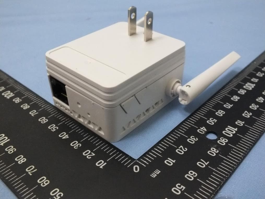
Click to zoom
Application Details
- Equipment Class
- DTS - Digital Transmission System
- Date of Grant
- Jun 26, 2014
- Application Purpose
- Original Equipment
- Date of Application
- Jun 26, 2014
- Equipment Note
- N300 WiFi Range Extender
- Frequency Range
- 2422.00000000 - 2452.00000000
- Company
- Netgear Incorporated
- Country
- United States
Documents & Files
Document Text
Text extracted from the exhibit documents filed with the FCC. Open a document above to read the original.
Users Manual
Installation N300 WiFi Range Extender Model EX2700 2 Getting Started The NETGEAR WiFi Range Extender increases the distance of a WiFi network by boosting the existing WiFi signal and enhancing the overall signal quality over long distances. An extender repeats the signals from an existing WiFi router or access point. Existing WiFi Sometimes your router does not provide the WiFi cover age you need. WiFi Range Extender Boosts the range of your existing WiFi and creat es a str onger signal in hard-to-reach areas. 3 Meet Your Extender Before you install your extender, familiarize yourself with its LEDs, buttons, and port. Router Link LED Device Link LED Power LED WPS LED Power On/Off button WPS button Factory Reset button Ethernet port 4 LED Descriptions Router Link LEDThis LED indicates the connection between the extender and the router or access point. Solid green. Best connection. Solid amber. Good connection. Solid red. Poor connection. Off. No connection. Device Link LEDThis LED indicates the connection between the extender and a computer or mobile device. Solid green. Best connection. Solid amber. Good connection. Solid red. Poor connection. Off. No connection. Power LEDSolid amber. The extender is booting. Solid green. The extender is powered on. Off. The extender is powered off. WPS LEDSolid green. WiFi security is enabled (WPA or WPA2). Blinking green. A WPS connection is being established. Off. WiFi security is not enabled. Note: If the Router Link LED or Device LED is amber or red, see ”Find the Best Location” on page 10. 5 Install the WiFi Extender Place the extender, apply power, and connect it to your WiFi network. Place the Extender and Apply Power 1. Place your extender in the same room as your WiFi router. Proximity to the WiFi router is required only during the initial setup process. 2. Plug the extender into an electrical outlet. The Power LED lights green. If the Power LED does not light, press the Power button. Connect to an Existing WiFi Network To extend the range of your WiFi network, you must connect the extender to your existing WiFi network. You can do this in one of two ways: • Connect with WPS. For more information, see ”Connect with WPS” on page 6. • Connect with web browser setup. For more information, see ”Connect with Web Browser Setup” on page 7. 6 Connect with WPS Wi-Fi Protected Setup (WPS) lets you join a secure WiFi network without typing the network name and password. Note: WPS does not support WEP network security. If you are using WEP security, follow the instructions in “Connect with Web Browser Setup” on page 7. 1. Press the WPS button on the side panel of the extender. The WPS LED blinks. 2. Within two minutes, press the WPS button on your router or access point. The WPS LED on the extender lights solid green, the Router Link LED lights, and the extender connects to your existing WiFi network. If the Router Link LED does not light, try again. If it still does not light, see “Connect with Web Browser Setup” on page 7. 3. Find the new extender network name. The extender’s wireless network name (SSID) changes to your existing WiFi network name, with _EXT at the end of the name, for example: • Existing WiFi network name. MyNetworkName • New extended network name. MyNetworkName_EXT 7 4. Connect your WiFi devices to the new extender network. Use the same WiFi password that you use for your WiFi router. 5. Unplug the extender and move it to a new location closer to the area with a poor WiFi signal. The location that you choose must be within the range of your existing WiFi router network. 6. Plug the extender into an electrical outlet. The Power LED lights green. If the Power LED does not light, press the Power button. 7. Use the Router Link LED on the front panel to help you choose a spot where the extender-to-router connection is optimal. Connect with Web Browser Setup 1. Use a WiFi network manager on a computer or mobile device to find and connect to the NETGEAR_EXT (SSID) WiFi network. After the connection with the computer or mobile device is established, the Device Link LED lights. 2. Open a web browser window from the same computer or mobile device. The browser takes you directly to the NETGEAR genie Smart Setup. If you are not automatically directed to NETGEAR genie, launch a web 8 browser and type www.mywifiext.net in the address field. Enter admin for the user name and password for the password. 3. Select a WiFi network to extend and click the Continue button. 4. Type the network password (also called passphrase or security key) in the Password field, and click the Continue button. 5. In the Name field, type the name (SSID) for your new extender WiFi network and click the Continue button. You can use the same security settings as your existing network by selecting the check box. The settings are applied and the following screen displays. 9 On iPads, iPhones, and MacBook computers, this screen automatically closes. 6. Use a WiFi network manager on the computer or mobile device to connect to the extender’s newly created WiFi network. Repeat this step for all of your computers and mobile devices. 7. If the screen is still displayed on your computer or device, select the check box at the bottom of the screen and click the Continue button. 10 8. Unplug the extender and move it to a new location closer to the area with a poor WiFi signal. The location that you choose must be within the range of your existing WiFi router network. 9. Plug the extender into an electrical outlet. The Power LED lights green. If the Power LED does not light, press the Power button. Use the Router Link LED to help you choose a spot where the extender-to-router connection is optimal. Find the Best Location If the WiFi signal is weak, the first time you join the extender network, the Router Link LED or Device Link LED is amber or red. If this happens, adjust the position of the extender. • If the Router Link LED is amber or red, move the extender closer to the router. • If the…
Text truncated - open the document above for the full version.
Users Manual
Notification of Compliance Regulatory Compliance Information This document includes user requirements for operating NETGEAR products in accordance with national laws including usage of radio spectrum and operation of radio devices. Failure of the end-user to comply with the applicable requirements may result in unlawful operation and adverse action against the end-user by the applicable national regulatory authority. The NETGEAR product firmware limits operation to only the channels allowed in a particular region or country. Therefore, all options described in this document may not be available in your version of the product. This document applies to both Class A and Class B devices: Class A devices are intended to be used in a commercial or industrial environment. They are not intended to be used in a residential home or be available for general public use. Class B devices are intended to be used in a residential setting, and may also be used in commercial and industrial applications. Examples of Class B devices are telephones, personal computers, and residential data gateways. Fuses should only be installed by service personnel. NETGEAR recommends the use of 26 AWG or larger gauge phone line cords. Europe – EU Declaration of Conformity This section applies to products bearing the CE or CE! mark: Products bearing the CE or CE! mark comply with the following EU directives: EMC Directive 2004/108/EC Low Voltage Directive 2006/95/EC Ecodesign Directive 2009/125/EC RoHS Directive 2011/65/EU If the product has telecommunications functionality, it also complies with the requirement of the following EU directive: R&TTE Directive 1999/5/EC Compliance with these directives implies conformity to harmonized European standards that are noted in the EU Declaration of Conformity. The EU CE Declaration of Conformity may be found at http://support.netgear.com/app/answers/detail/a_id/11621/. Caution for installing this equipment outdoors: (Valid in all EU member states, EFTA states, and Switzerland.) Be aware that outdoor installations require special attention and will only be handled by trained and qualified installation personnel. No one from the general public is permitted to install NETGEAR wireless products outdoors when external antennas, power and grounding must be installed for use. Particular attention has to be given allowed operational frequencies. Contact NETGEAR for instructions on how to contact an installer for outdoor operations if this product requires the special considerations for outdoor installations. For detailed iformation concerning installations in France, the user should contact the national spectrum authority in France (http://www.arcep.fr/ ) The following paragraphs apply to WN2500RP: This device is a 2.4GHz and 5GHz wideband transmission system (transceiver), intended for indoor use only in all EU member states, EFTA states, and Switzerland. In Italy the end-user should apply for a license at the national spectrum authorities in order to obtain authorization to use the device for setting up outdoor radio links and/or for applying public access to telecommunications and/or network services. This device may not be used for setting up outdoor radio links in France and in some areas the RF output power may be limited to 10mW EIRP in the frequency range of 2454-2483.5 MHz. For detailed information the end-user should contact the national spectrum authority in France. Warning NETGEAR Class A products that may be utilized in domestic/residential environments may cause radio interference in which case the user may be required to take adequate measures. FCC Requirements for Operation in the United States Information in this section applies to products bearing the FCC mark (or statement): FCC Information to User This NETGEAR product does not contain any user serviceable components and is to be used with approved antennas only. Any product changes or modifications will invalidate all applicable regulatory certifications and approvals. The following statement applies to these products: A6210 JWNR2010v5 WN3000RPv2 C6300 R6050 WN3500RP D6200V2 R7500 WNDR3400v3 EX6100 R8000 WNR2010 EX6200 STS7000 WNR2020 HMNC100 VEGN2200 WNR614 JR6150 WN370 WNR618 JWNR2000v5 WN2500RP EX2700 This device and its antenna(s) must not be co-located or operating in conjunction with any other antenna or transmitter except in accordance with FCC multi-transmitter product procedures. FCC Guidelines for Human Exposure The NETGEAR product complies with FCC radiation exposure limits set forth for an uncontrolled environment. The equipment should be installed and operated with minimum distance of 20cm between the radiator and your body. The following statement applies to this product: C6300XB3 This product complies with FCC radiation exposure limits set forth for an uncontrolled environment. The device should be installed and operated with minimum distance of 25cm between the radiator and your body. The following statement applies to this product: R8000 This product complies with FCC radiation exposure limits set forth for an uncontrolled environment. The device should be installed and operated with minimum distance of 30cm between the radiator and your body. FCC Declaration of Conformity We, NETGEAR, Inc., 350 East Plumeria Drive, San Jose, CA 95134, declare under our sole responsibility that this product complies with Part 15 Subpart B of FCC CFR47 Rules. Operation is subject to the following two conditions: The device may not cause harmful interference, and The device must accept any interference received, including interference that may cause undesired operation. FCC Radio Frequency Interference Warnings & Instructions The NETGEAR product has been tested and found to comply with the limits for a Class B digital device, pursuant to Part 15 of the FCC Rules. These limits are designed to provide reasonable protection against harmful interferenc…
Text truncated - open the document above for the full version.
Cover Letter(s)
NETGEAR Inc. 350 East Plumeria Drive San Jose, California 95134 USA Date: June 23, 2014 Federal Communications Commission Authorization and Evaluation Division 7435 Oakland Mills Rd Columbia MD 21046-1609 Subject: Request for confidentiality FCC ID: PY314200263 To whom it may concern: Short-term confidentiality Pursuant to DA 04-1705 of the Commission’s public notice, in order to comply with the marketing regulations in 47CFR §2.803 and the importation rules in 47 CFR §2.1204, while ensuring that business sensitive information remains confidential until the actual marketing of newly authorized devices. We are requesting the commission to grant short-term confidentiality request on the following attachments for 180 days. ☒ Internal Photographs ☒ External Photographs ☒ User's manual ☒ Test Set up photo Permanent confidentiality Pursuant to Sections 0.457 and 0.459 of the Commission’s Rules, the Applicant Hereby requests confidential treatment of information accompanying this Application As outlined below: ☒ Block Diagram ☒ Schematics ☒ Operation description The above materials contain trade secrets and proprietary information not customarily released to the public. The public disclosure of these materials may be harmful to the applicant and provide unjustified benefits to its competitors. The applicant understands that pursuant to Section 0.457 of the Rules, disclosure of this application and all accompanying documentation will not be made before the date of the Grant for this application. Should you require any further information, please contact the undersigned. Thank you for your consideration in this matter. Applicant : NETGEAR, Inc. Address : 350 East Plumeria Drive, San Jose, California 95134, USA Signature : _________________________________ Name and Job Title. : David Kay / Regulatory Compliance Manager E-mail : [email protected] Tel. : 408-890-3160
Cover Letter(s)
NETGEAR Inc. 350 East Plumeria Drive San Jose, California 95134 USA Date: June 23, 2014 Subject: Ad Hoc Mode Function Declaration To whom it may concern, We, NETGEAR, Inc. declare that the device does not support any non-US channels and country code selection in all the operational mode(s) for the following product. FCC ID: PY314200263 IC : 4054A-14200263 Regards, Applicant’s company name : NETGEAR, Inc. Applicant’s company address : 350 East Plumeria Drive, San Jose, California 95134, USA Signature : Name and Job Title : David Kay / Regulatory Compliance Manager E-Mail : [email protected] Tel. : 408-890-3160
Cover Letter(s)
NETGEAR Inc. 350 East Plumeria Drive San Jose, California 95134 USA Date: 2014/6/23 Federal Communications Commission 7435 Oakland Mills Rd Columbia MD 21046-1609 Subject: Product Certification Representative Authorization Letter FCC ID: PY314200263 To whom it may concern: We the undersigned, hereby authorize following person to act as our agent in the preparation of an application for equipment authorization o the FCC Rules and Regulations. International Certification Corp. Address : No.3-1, Lane 6, Wen San 3rd St. Kwei Shan Hsiang, Tao Yuan Hsein 333, Taiwan (R.O.C.) Name : Gary Chang Job Title : Manager e-mail : [email protected] Webs We further certifies that neither the applicant nor any party to this application, as defined in 47 CFR Ch. 1.2002(b), is subject to a denial to Federal benefits, that include FCC benefits, pursuant to section 5301 of the Anti-Drug Abuse Act of 1998, 21 U.S.C. 835(a). This appointment also includes the authority to complete FCC Form 731 on our behalf and sign the application as an authorized agent. Applicant : NETGEAR, Inc. Address : 350 East Plumeria Drive, San Jose, California 95134, USA Signature : _________________________________ Name and Job Title. : David Kay / Regulatory Compliance Manager E-mail : [email protected] Tel. : 408-890-3160
External Photos
Project No.: EP461202 Page No. : 1 of 11 Photographs of EUT
ID Label/Location Info
SHEET: AUTHOR:TITLE: P/N: REV: THIS DOCUMENT AND THE DATA DISCLOSED HEREIN OR WHEREWITH IS NOT TO BE REPRODUCED, USED OR DISCLOSED IN WHOLE OR IN PART TO ANYONE WITHOUT THE PERMISSION OF NETGEAR, INC. REV DESCRIPTION OF REVISION ENG APPD DATE Pantone Cool Gray 11C 01AW-12910-011 of 1 AW, EX2700NA V1, PLBLJ RAMONES J RAMONESINITIAL DOCUMENT CREATION 01 7 15APR14 NOTE: 1. REFER TO NETGEAR SPEC. DOC-00093 FOR COLOR TOLERANCES. 2. SCALE IS 2:1 3. INK COLOR IS SHOWN TO THE RIGHT. 4. DIE LINES ARE MAGENTA COLOR AND DO NOT PRINT. 5. MAC & SERIAL NUMBERS TO BE PRINTED BY THE ODM. 6. See NTGR DOC-00112 for SN standard. 7. NTGR SN and MAC address barcode to be encoded AIM USS Code39 and include printed characters below barcodes. 8. INSURE COUNTRY OF ORIGIN IS CORRECT. A. IF COUNTRY OF ORIGIN IS PRE-PRINTED, UNHIDE THE APPROPRIATE COUNTRY OF ORIGIN LAYER AND INCLUDE COUNTRY OF ORIGIN ON LABEL. B. IF COUNTRY OF ORIGIN IS POST-PRINTED USING A THERMAL PRINTER (OR EQUIVALENT), OMIT TEXT FROM ARTWORK (USE LAYERS). Made in Taiwan Made in China Back Label location
Internal Photos
Project No.: EP461202 Page No. : 2 of 11 Project No.: EP461202 Page No. : 3 of 11 Project No.: EP461202 Page No. : 4 of 11 Project No.: EP461202 Page No. : 5 of 11 Project No.: EP461202 Page No. : 6 of 11 Project No.: EP461202 Page No. : 7 of 11 Project No.: EP461202 Page No. : 8 of 11 Project No.: EP461202 Page No. : 9 of 11 Project No.: EP461202 Page No. : 10 of 11 Project No.: EP461202 Page No. : 11 of 11
RF Exposure Info
Report No.: FA461202 Page : 1 of 5 Report Version: Rev. 01 FCC RF Exposure Report FCC ID : PY314200263 Equipment : N300 WiFi Range Extender Model No. : EX2700 Brand Name : NETGEAR Applicant : NETGEAR, Inc. Address : 350 East Plumeria Drive, San Jose, California 95134, U.S.A. Standard : 47 CFR FCC Part 2.1091 Received Date : Jun. 06, 2014 Tested Date : Jun. 06 ~ Jun. 10, 2014 We, International Certification Corp., would like to declare that the tested sample has been evaluated and in compliance with the requirement of the above standards. The test results contained in this report refer exclusively to the product. It may be duplicated completely for legal use with the approval of the applicant. It shall not be reproduced except in full without the written approval of our laboratory. Approved & Reviewed by: Gary Chang / Manager Ty: XXX Report No.: FA461202 Page : 2 of 5 Report Version: Rev. 01 Table of Contents 1 MPE EVALUATION OF MOBILE DEVICES ......................................................................................... 4 1.1 LIMITS FOR GENERAL POPULATION/UNCONTROLLED EXPOSURE............................................. 4 1.2 MPE EVALUATION FORMULA ............................................................................................................. 4 1.3 MPE EVALUATION RESULTS .............................................................................................................. 4 2 TEST LABORATORY INFORMATION ................................................................................................. 5 Report No.: FA461202 Page : 3 of 5 Report Version: Rev. 01 Release Record Report No. Version Description Issued Date FA461202 Rev. 01 Initial issue Jun. 23, 2014 Report No.: FA461202 Page : 4 of 5 Report Version: Rev. 01 1 MPE EVALUATION OF MOBILE DEVICES Human exposure to RF emissions from mobile devices (47 CFR §2.1091) may be evaluated based on the MPE limits adopted by the FCC for electric and magnetic field strength and/or power density, as appropriate, since exposures are assumed to occur at distances of 20 cm or more from persons. 1.1 LIMITS FOR GENERAL POPULATION/UNCONTROLLED EXPOSURE Frequency Range (MHz) Power Density (mW /cm 2 ) Averaging Time (minutes) 300~1500 F/1500 30 1500~100000 1.0 30 1.2 MPE EVALUATION FORMULA Pd = 2 **4RPi Pt Where Pd= Power density in mW/cm 2 Pt= EIRP in mW Pi= 3.1416 R= Measurement distance 1.3 MPE EVALUATION RESULTS Frequency Range (MHz) Maximum Conducted Power (dBm) Antenna Gain (dBi) Distance (cm) Power Density (mW/cm 2 ) Limit (mW/cm 2 ) 2412~2462 24.04 2.2 20 0.084 1 Report No.: FA461202 Page : 5 of 5 Report Version: Rev. 01 2 Test laboratory information Established in 2012, ICC provides foremost EMC & RF Testing and advisory consultation services by our skilled engineers and technicians. Our services employ a wide variety of advanced edge test equipment and one of the widest certification extents in the business. International Certification Corp, it is our definitive objective is to institute long term, trust-based associations with our clients. The expectation we set up with our clients is based on outstanding service, practical expertise and devotion to a certified value structure. Our passion is to grant our clients with best EMC / RF services by oriented knowledgeable and accommodating staff. Our Test sites are located at Linkou District and Kwei Shan Hsiang. Location map can be found on our website http://www.icertifi.com.tw. Linkou Kwei Shan Tel: 886-2-2601-1640 Tel: 886-3-271-8666 No. 30-2, Ding Fwu Tsuen, Lin Kou District, New Taipei City, Taiwan, R.O.C. No. 3-1, Lane 6, Wen San 3rd St., Kwei Shan Hsiang, Tao Yuan Hsien 333, Taiwan, R.O.C. If you have any suggestion, please feel free to contact us as below information Tel: 886-3-271-8666 Fax: 886-3-318-0155 Email: [email protected] ══END══
Test Report
Report No.: FR461202 Page : 1 of 62 Report Version: Rev. 02 FCC Test Report FCC ID : PY314200263 Equipment : N300 WiFi Range Extender Model No. : EX2700 Brand Name : NETGEAR Applicant : NETGEAR, Inc. Address : 350 East Plumeria Drive, San Jose, California 95134, U.S.A. Standard : 47 CFR FCC Part 15.247 Received Date : Jun. 06, 2014 Tested Date : Jun. 06 ~ Jun. 10, 2014 We, International Certification Corp., would like to declare that the tested sample has been evaluated and in compliance with the requirement of the above standards. The test results contained in this report refer exclusively to the product. It may be duplicated completely for legal use with the approval of the applicant. It shall not be reproduced except in full without the written approval of our laboratory. Approved & Reviewed by: Gary Chang / Manager Ty: XXX Report No.: FR461202 Page : 2 of 62 Report Version: Rev. 02 Table of Contents 1 GENERAL DESCRIPTION .................................................................................................................... 5 1.1 Information .............................................................................................................................................. 5 1.2 Local Support Equipment List ................................................................................................................ 7 1.3 Test Setup Chart .................................................................................................................................... 7 1.4 The Equipment List ................................................................................................................................ 8 1.5 Test Standards ....................................................................................................................................... 9 1.6 Measurement Uncertainty ...................................................................................................................... 9 2 TEST CONFIGURATION ....................................................................................................................... 9 2.1 Testing Condition ................................................................................................................................. 10 2.2 The Worst Test Modes and Channel Details ....................................................................................... 10 3 TRANSMITTER TEST RESULTS ........................................................................................................ 11 3.1 Conducted Emissions ........................................................................................................................... 11 3.2 6dB and Occupied Bandwidth .............................................................................................................. 14 3.3 RF Output Power .................................................................................................................................. 17 3.4 Power Spectral Density ........................................................................................................................ 19 3.5 Unwanted Emissions into Restricted Frequency Bands ...................................................................... 21 3.6 Emissions in non-restricted frequency bands ...................................................................................... 49 4 TEST LABORATORY INFORMATION ............................................................................................... 62 Report No.: FR461202 Page : 3 of 62 Report Version: Rev. 02 Release Record Report No. Version Description Issued Date FR461202 Rev. 01 Initial issue Jun. 23, 2014 FR461202 Rev. 02 Modified power supply type from 0.3A to 0.1A. Jun. 25, 2014 Report No.: FR461202 Page : 4 of 62 Report Version: Rev. 02 Summary of Test Results FCC Rules Test Items Measured Result 15.207 Conducted Emissions [dBuV]: 0.183MHz 55.36 (Margin -8.97dB) - QP Pass 15.247(d) 15.209 Radiated Emissions [dBuV/m at 3m]: 2483.50MHz 53.87 (Margin -0.13dB) - AV Pass 15.247(b)(3) Fundamental Emission Output Power Power [dBm]: 11b: 24.04 11g: 23.60 HT20: 23.48 HT40: 18.38 Pass 15.247(a)(2) 6dB Bandwidth Meet the requirement of limit Pass 15.247(e) Power Spectral Density Meet the requirement of limit Pass 15.203 Antenna Requirement Meet the requirement of limit Pass Report No.: FR461202 Page : 5 of 62 Report Version: Rev. 02 1 General Description 1.1 Information 1.1.1 Specification of the Equipment under Test (EUT) RF General Information Frequency Range (MHz) IEEE Std. 802.11 Ch. Freq. (MHz) Channel Number Transmit Chains (N TX ) Data Rate / MCS 2400-2483.5 b 2412-2462 1-11 [11] 2 1-11 Mbps 2400-2483.5 g 2412-2462 1-11 [11] 2 6-54 Mbps 2400-2483.5 n (HT20) 2412-2462 1-11 [11] 2 MCS 0-15 2400-2483.5 n (HT40) 2422-2452 3-9 [7] 2 MCS 0-15 Note 1: RF output power specifies that Maximum Conducted (Average) Output Power. Note 2: 802.11b uses a combination of DSSS-DBPSK, DQPSK, CCK modulation. Note 3: 802.11g/n uses a combination of OFDM-BPSK, QPSK, 16QAM, 64QAM modulation. 1.1.2 Antenna Details Ant. No. Type Gain (dBi) Connector Remark 1 Dipole 2.2 UFL --- 2 Dipole 2.2 UFL --- 1.1.3 Power Supply Type of Equipment under Test (EUT) Power Supply Type 100-240Vac, 50-60Hz, 0.1A 1.1.4 Accessories N/A Report No.: FR461202 Page : 6 of 62 Report Version: Rev. 02 1.1.5 Channel List Frequency band (MHz) 2400~2483.5 802.11 b / g / n HT20 802.11n HT40 Channel Frequency(MHz) Channel Frequency(MHz) 1 2412 3 2422 2 2417 4 2427 3 2422 5 2432 4 2427 6 2437 5 2432 7 2442 6 2437 8 2447 7 2442 9 2452 8 2447 --- --- 9 2452 --- --- 10 2457 --- --- 11 2462 --- --- 1.1.6 Test Tool and Duty Cycle Test Tool MT7620QA, V1.0.6.0 Duty Cycle and Duty Factor Mode Duty cycle (%) Duty factor (dB) 11b 100.00% 0.00 11g 99.50% 0.02 HT20 98.74% 0.05 HT40 98.33% 0.07 Report No.: FR461202 Page : 7 of 62 Report Version: Rev. 02 1.1.7 Power Setting Modulation Mode Test Frequency (MHz) Power Set 11…
Text truncated - open the document above for the full version.
Test Setup Photos
Report No.: FR461202 Page: : 1 of 2 Report Version: Rev. 01 Photographs of the Test Configuration Conducted Emission Test Report No.: FR461202 Page: : 2 of 2 Report Version: Rev. 01 Radiated Emission Test
Contact Information
Applicant
David Kay
Test Firm
International Certification Corp.Fu-Cheng Chuang
Technical Specifications
| # | Rule Parts | Frequency Range | Power Output |
|---|---|---|---|
| 2 | 15C | 2.42 GHz - 2.45 GHz | 69.00 mW |
Other Applications from Netgear Incorporated

PY325100647
Aug 04, 2026BE5000 Dual-Band PoE 2.5G Insight Managed WiFi 7 Outdoor Access Point
Equipment Class
DTS - Digital Transmission SystemPY325300652
May 12, 2026BE5000 Dual-Band PoE 2.5G Insight Managed WiFi 7 Access Point
Equipment Class
NII - Unlicensed National Information Infrastructure TXPY325400656
Apr 16, 2026Orbi Outdoor Satellite
Equipment Class
DTS - Digital Transmission SystemPY324400640
Dec 12, 2025Orbi 11BE WiFi 7 Tri-band Router, Orbi 11BE WiFi 7 Tri-band Satellite
Equipment Class
NII - Unlicensed National Information Infrastructure TXPY324100618
Jul 31, 2024Nighthawk 5G Mobile Router
Equipment Class
PCB - PCS Licensed Transmitter