PY314200280AC1900 WiFi Range Extender
Netgear Incorporated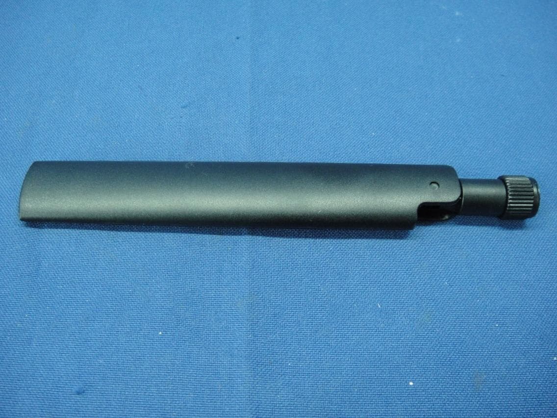
Click to zoom
Application Details
- Equipment Class
- NII - Unlicensed National Information Infrastructure TX
- Date of Grant
- Dec 07, 2014
- Application Purpose
- Original Equipment
- Date of Application
- Dec 07, 2014
- Equipment Note
- AC1900 WiFi Range Extender
- Frequency Range
- 5180.00000000 - 5240.00000000
- Company
- Netgear Incorporated
- Country
- United States
Documents & Files
Document Text
Text extracted from the exhibit documents filed with the FCC. Open a document above to read the original.
Users Manual
1. Attach the antennas. Attach the antennas to the connectors and turn them clockwise to tighten. Bend and rotate the antennas into position. Double check that the antennas are properly tightened. 2. Turn on your extender. Place the extender close to your WiFi router. Plug the extender into an electrical outlet. Press the Power button if necessary. 3. Connect to your WiFi router. Press the WPS button on the extender. The Link Rate LEDs and Device to Extender LED blink green. Within two minutes, press the WPS button on your WiFi router. After a few seconds, the 2.4 GHZ Link Rate LED lights green, indicating a good connection between your WiFi router and your extender. If the 2.4 GHz Link Rate LED does not light, or the LED is blinking amber, try again. If the LED still does not light, follow the instructions for No WPS button on the right. 4. Add a WiFi band. If your WiFi router supports the 5 GHz band (not all routers do), and you want to extend that band, repeat Step 2 and check that the 5 GHz Link Rate LED lights solid green to confirm the connection. 5. Choose a location and check the signal strength. Now that the extender is connected to your WiFi router, you can move it to a location that will boost your WiFi range. The location you choose must be within the range of your existing WiFi router network. The Link Rate LEDs help you choose a spot where the extender-to-router connection is optimal. See the Indicator LEDs section on the back to learn how the LEDs show the best connection. If you get no connection or a poor connection, move the extender closer to your WiFi router and try again until the 2.4 GHz or 5 GHz Link Rate LED lights green. 6. Connect your WiFi devices. Take your WiFi device to the location with poor WiFi router coverage. Find the new extender network name: Existing network name: MyNetworkName New extended network name: MyNetworkName_2GEXT or MyNetworkName_5GEXT Select the new network and use your WiFi router password to connect. You are now using your extended WiFi network. 1. Attach the antennas. Attach the antennas to the connectors and turn them clockwise to tighten. Bend and rotate the antennas into position. Double check that the antennas are properly tightened. 2. Turn on your extender. Place the extender close to your WiFi router. Plug the extender into an electrical outlet. Press the Power button if necessary. 3. Connect to the extender. On a computer, tablet, or smartphone, open the WiFi connection manager and connect to the extender network called NETGEAR_EXT. When you are connected to the extender, the Device to Extender LED lights solid green. 4. Set up with NETGEAR genie. Launch a web browser. You are automatically taken to a login screen. If a login screen does not display, go to www.mywifiext.net. To set up your extender, do the following: a. Click the NEW EXTENDER SETUP button. b. Complete the Extender Setup screen and click the NEXT button. c. Click the WiFi Range Extender button. d. Click the Smart Setup button. e. Select a WiFi network to extend and click the Next button. If you do not want to extend both WiFi bands, clear the 2.4GHz WiFi Networks or the 5GHz WiFi Networks checkbox. f. In the Password field, type the existing WiFi network password and click the Next button. g. Set the network name (SSID) and password for your extender and click the Next button. h. Use a WiFi network manager on the computer or WiFi device to connect to the new extended WiFi network. 5. Choose a location and check the signal strength. Now that the extender is connected to your WiFi router, you can move it to a location that will boost your WiFi range. The location you choose must be within the range of your existing WiFi router network. The Link Rate LEDs help you choose a spot where the extender-to-router connection is optimal. See the Indicator LEDs section on the back to learn how the LEDs show the best connection. If you get no connection or a poor connection, move the extender closer to your WiFi router and try again until the 2.4 GHz or 5 GHz Link Rate LED lights green. AC1900 WiFi Range Extender Model EX7000 Quick Start Guide Getting Started Does your WiFi router have a WPS button? Ye s No (or not sure) Wi-Fi Protected Setup (WPS) is an easy way to connect WiFi devices. The button might look like one of these: AC1900 WiFi Range Extender Model EX7000 Quick Start Guide Hardware Front Panel and Side PanelRear Panel Indicator LEDs Support After installing your extender, locate the serial number on the label and use it to register your product at https://my.netgear.com. You must register your product before you can use NETGEAR telephone support. NETGEAR recommends registering your product through the NETGEAR website. For product updates and web support, visit http://support.netgear.com. You can get the user manual online at http://downloadcenter.netgear.com or through a link in the product’s user interface. NETGEAR recommends that you use only the official NETGEAR support resources. For the current EU Declaration of Conformity, visit: http://support.netgear.com/app/answers/detail/a_id/11621/. For regulatory compliance information, visit http://www.netgear.com/about/regulatory/. See the regulatory compliance document before connecting the power supply. NETGEAR, the NETGEAR logo, and Connect with Innovation are trademarks and/or registered trademarks of NETGEAR, Inc. and/or its subsidiaries in the United States and/or other countries. Information is subject to change without notice. Other brand and product names are registered trademarks or trademarks of their respective holders. © NETGEAR, Inc. All rights reserved. NETGEAR, Inc. 350 East Plumeria Drive, San Jose, CA 95134 USA August 2014 BETA DOCUMENT This LED indicates the 2.4 GHz WiFi connection between the extender and the router. Solid green. Best connection Solid amber. Good connection Solid red. Poor connection Off. No connection This LED indicates the 5 GHz WiFi connection between the extender and the route…
Text truncated - open the document above for the full version.
Attestation Statements
NETGEAR, INC. 350 East Plumeria Drive, San Jose, CA 95134, USA Tel:408-890-3657/Fax:408-907-8097 Date: 2014/11/10 G E N E R A L D E C L A R A T I O N We, NETGEAR, INC. declare that the device does not support channel 12 ~ 14 in 2.4GHz band and any non- US channels in all the operational mode(s) for the following product. FCC ID: PY314200280 If you have any questions regarding the authorization, please don’t hesitate to contact us. Thank you! ------------------------------------------------------ David Kay/ Regulatory Compliance Manager NETGEAR, INC. TEL: 4088903657 FAX: 4089078097 E-mail: [email protected]
Cover Letter(s)
NETGEAR, INC. 350 East Plumeria Drive, San Jose, CA 95134, USA Tel:408-890-3657/Fax:408-907-8097 P O W E R O F A T T O R N E Y Date: 2014/11/10 FCC ID: PY314200280 To whom it may concern: We, the undersigned, hereby authorize Amanda Wu of Bureau Veritas Consumer Products Services (H.K.) Ltd., Taoyuan Branch (BV CPS Taoyuan) of Taiwan to act on our behalf in all manners relating to FCC application for equipment authorization, including signing of all documents relating to these matters. Any and all acts carried out by Amanda Wu of BV CPS Taoyuan on our behalf shall have the same effect as acts of our own. If you have any questions regarding the authorization, please don’t hesitate to Contact us. Thank you! Sincerely yours, ------------------------------------------------------ David Kay/ Regulatory Compliance Manager NETGEAR, INC. TEL: 4088903657 FAX: 4089078097 E-mail: [email protected]
Cover Letter(s)
NETGEAR, INC. 350 East Plumeria Drive, San Jose, CA 95134, USA Tel:408-890-3657/Fax:408-907-8097 Date: 2014/11/10 FCC ID: PY314200280 Federal Communications Commission Authorization and Evaluation Division Confidentiality Request Pursuant to Sections 0.457 and 0.459 of the Commission’s Rules, the Applicant hereby requests confidential treatment of information accompanying this Application as outlined below: Schematics Block Diagram Software Operational Description The above materials contain trade secrets and proprietary information not customarily released to the public. The public disclosure of these matters might be harmful to the Applicant and provide unjustified benefits to its competitors. The Applicant understands that pursuant to Rule 0.457, disclosure of this Application and all accompanying documentation will not be made before the date of the Grant for this application. Sincerely yours, ------------------------------------------------------ David Kay/ Regulatory Compliance Manager NETGEAR, INC. TEL: 4088903657 FAX: 4089078097 E-mail: [email protected]
Cover Letter(s)
NETGEAR, INC. 350 East Plumeria Drive, San Jose, CA 95134, USA Tel:408-890-3657/Fax:408-907-8097 Federal Communications Commission Authorization and Evaluation Division Date: November 11, 2014 Confidentiality Request FCC ID: PY314200280 Pursuant to Sections 0.457 and 0.459 of the commission’s rules, we request short-term confidential treatment for the following information until 180 days in order to ensure sensitive business information remains confidential until the actual marketing of the device: External photos Test Setup photos User’s manual Internal Photos Sincerely yours, ------------------------------------------------------ David Kay/ Regulatory Compliance Manager NETGEAR, INC. TEL: 4088903657 FAX: 4089078097 E-mail: [email protected]
External Photos
Report No. : 140901E08 Page 1 CONSTRUCTION PHOTOS OF EUT Report No. : 140901E08 Page 2 Report No. : 140901E08 Page 3 Report No. : 140901E08 Page 4 Adapter : SAS030F1 NA Report No. : 140901E08 Page 5 Report No. : 140901E08 Page 6 Adapter : P030WF120B Report No. : 140901E08 Page 7
ID Label/Location Info
SHEET: AUTHOR:TITLE: P/ N : REV: THIS DOCUMENT AND THE DATA DISCLOSED HEREIN OR WHEREWITH IS NOT TO BE REPRODUCED, USED OR DISCLOSED IN WHOLE OR IN PART TO ANYONE WITHOUT THE PERMISSION OF NETGEAR, INC. REV DESCRIPTION OF REVISION ENG APPDD AT E 01 AW-13019-021 of 1 AW,PLBL,EX7000,V2M HUMPHREY 02SEP14M HUMPHREYINITIAL DOCUMENT CREATION01 Pantone 877C Black NOTE: 1. REFER TO NETGEAR SPEC. DOC-00093 FOR COLOR TOLERANCES. 2. INK COLOR IS SHOWN TO THE RIGHT. 3. DIE LINES ARE MAGENTA COLOR AND DO NOT PRINT. 4. MAC & SERIAL NUMBERS TO BE PRINTED BY THE ODM. 5. See NTGR DOC-00112 for SN standard. 6. NTGR SN and MAC address barcode to be encoded AIM USS Code39 and include printed characters below barcodes. 7. INSURE COUNTRY OF ORIGIN IS CORRECT. A. IF COUNTRY OF ORIGIN IS PRE-PRINTED, UNHIDE THE APPROPRIATE COUNTRY OF ORIGIN LAYER AND INCLUDE COUNTRY OF ORIGIN ON LABEL. B. IF COUNTRY OF ORIGIN IS POST-PRINTED USING A THERMAL PRINTER (OR EQUIVALENT), OMIT TEXT FROM ARTWORK (USE LAYERS). 8. THE BACK OF PRODUCT LABEL SHOULD BE BLACK WITHOUT THE OF THE TRACE OF FRONT ARTWORK. 9. ALIGN THE PRINTED LABELS AT THE CORNER OF THE MARKS WHEN PLACE THE LABELS. ResetPower (Fig. 1) FCC ID: PY314200280 FCC LABEL LOCATION The label will be permanently affixed at a conspicuous location on the device. (Pull & Push) EUT Back
Internal Photos
Report No. : 140901E08 Page 1 CONSTRUCTION PHOTOS OF EUT Report No. : 140901E08 Page 2 Report No. : 140901E08 Page 3 Report No. : 140901E08 Page 4
RF Exposure Info
Report No.: SA140901E08 1 of 10 Report Format Version 5.2.1 RF EXPOSURE REPORT REPORT NO.: SA140901E08 MODEL NO.: EX7000 FCC ID: PY314200280 RECEIVED:Sep. 01, 2014 TESTED:Oct. 27 to 30, 2014 ISSUED:Dec. 04, 2014 APPLICANT: NETGEAR, Inc. ADDRESS: 350 East Plumeria Drive San Jose, CA 95134 ISSUED BY: Bureau Veritas Consumer Products Services (H.K.) Ltd., Taoyuan Branch Hsin Chu Laboratory LAB ADDRESS : No. 81-1, Lu Liao Keng, 9th Ling, Wu Lung Tsuen, Chiung Lin Hsiang, Hsin Chu Hsien 307, Taiwan, R.O.C. TEST LOCATION (1): No. 81-1, Lu Liao Keng, 9th Ling, Wu Lung Tsuen, Chiung Lin Hsiang, Hsin Chu Hsien 307, Taiwan, R.O.C. TEST LOCATION (2): No. 49, Ln. 206, Wende Rd., Shangshan Tsuen, Chiung Lin Hsiang, Hsin Chu Hsien 307, Taiwan, R.O.C. This report should not be used by the client to claim product certification, approval, or endorsement by any government agencies. This report is for your exclusive use. Any copying or replication of this report to or for any other person or entity, or use of our name or trademark, is permitted only with our prior written permission. This report sets forth our findings solely with respect to the test samples identified herein. The results set forth in this report are not indicative or representative of the quality or characteristics of the lot from which a test sample was taken or any similar or identical product unless specifically and expressly noted. Our report includes all of the tests requested by you and the results thereof based upon the information that you provided to us. You have 60 days from date of issuance of this report to notify us of any material error or omission caused by our negligence, provided, however, that such notice shall be in writing and shall specifically address the issue you wish to raise. A failure to raise such issue within the prescribed time shall constitute your unqualified acceptance of the completeness of this report, the tests conducted and the correctness of the report contents. Unless specific mention, the uncertainty of measurement has been explicitly taken into account to declare the compliance or non-compliance to the specification Report No.: SA140901E08 2 of 10 Report Format Version 5.2.1 TABLE OF CONTENTS RELEASE CONTROL RECORD ..................................................................................... 3 1. CERTIFICATION ...................................................................................................... 4 2. RF EXPOSURE LIMIT ............................................................................................. 5 3. MPE CALCULATION FORMULA ............................................................................. 5 4. CLASSIFICATION .................................................................................................... 5 5. ANTENNA GAIN ...................................................................................................... 6 6. CALCULATION RESULT OF MAXIMUM CONDUCTED POWER .......................... 7 Report No.: SA140901E08 3 of 10 Report Format Version 5.2.1 RELEASE CONTROL RECORD ISSUE NO. REASON FOR CHANGE DATE ISSUED SA140901E08 Original release Dec. 04, 2014 Report No.: SA140901E08 5 of 10 Report Format Version 5.2.1 2. RF EXPOSURE LIMIT LIMITS FOR MAXIMUM PERMISSIBLE EXPOSURE (MPE) FREQUENCY RANGE (MHz) ELECTRIC FIELD STRENGTH (V/m) MAGNETIC FIELD STRENGTH (A/m) POWER DENSITY (mW/cm 2 ) AVERAGE TIME (minutes) LIMITS FOR GENERAL POPULATION / UNCONTROLLED EXPOSURE 300-1500 ... ... F/1500 30 1500-100,000 ... ... 1.0 30 F = Frequency in MHz 3. MPE CALCULATION FORMULA Pd = (Pout*G) / (4*pi*r 2 ) where Pd = power density in mW/cm 2 Pout = output power to antenna in mW G = gain of antenna in linear scale pi = 3.1416 r = distance between observation point and center of the radiator in cm 4. CLASSIFICATION The antenna of this product, under normal use condition, is at least 27cm away from the body of the user. So, this device is classified as Mobile Device. Report No.: SA140901E08 6 of 10 Report Format Version 5.2.1 5. ANTENNA GAIN 1. The antennas provided to the EUT, please refer to the following table: Antenna No. Brand Model Antenna Gain(dBi) Frequency range (MHz ~ MHz) Antenna Type Connecter Type Antenna L Netgear NA 2 2412~2477 5150~5250 5250~5350 5470~5725 5725~5850 Dipole Re-SMA Antenna M Netgear NA 2 2412~2477 5150~5250 5250~5350 5470~5725 5725~5850 Dipole Re-SMA Antenna R Netgear NA 2 2412~2477 5150~5250 5250~5350 5470~5725 5725~5850 Dipole Re-SMA Report No.: SA140901E08 7 of 10 Report Format Version 5.2.1 6. CALCULATION RESULT OF MAXIMUM CONDUCTED POWER For 15.247(2.4GHz): CDD Mode: 802.11b: FREQUENCY (MHz) CONDUCTED POWER (mW) ANTENNA GAIN (dBi) DISTANCE (cm) POWER DENSITY (mW/cm 2 ) LIMIT (mW/cm 2 ) 2412 ~ 2462 970.44 6.77 27 0.50354 1 Directional gain = 2dBi + 10log(3) = 6.77dBi 802.11g: FREQUENCY (MHz) CONDUCTED POWER (mW) ANTENNA GAIN (dBi) DISTANCE (cm) POWER DENSITY (mW/cm 2 ) LIMIT (mW/cm 2 ) 2412 ~ 2462 836.767 6.77 27 0.43418 1 Directional gain = 2dBi + 10log(3) = 6.77dBi VHT20: FREQUENCY (MHz) CONDUCTED POWER (mW) ANTENNA GAIN (dBi) DISTANCE (cm) POWER DENSITY (mW/cm 2 ) LIMIT (mW/cm 2 ) 2412 ~ 2462 911.213 6.77 27 0.47280 1 Directional gain = 2dBi + 10log(3) = 6.77dBi VHT40: FREQUENCY (MHz) CONDUCTED POWER (mW) ANTENNA GAIN (dBi) DISTANCE (cm) POWER DENSITY (mW/cm 2 ) LIMIT (mW/cm 2 ) 2422 ~ 2452 151.299 6.77 27 0.07851 1 Directional gain = 2dBi + 10log(3) = 6.77dBi Beamforming Mode: VHT20: FREQUENCY (MHz) CONDUCTED POWER (mW) ANTENNA GAIN (dBi) DISTANCE (cm) POWER DENSITY (mW/cm 2 ) LIMIT (mW/cm 2 ) 2412 ~ 2462 827.261 6.77 27 0.42924 1 Directional gain = 2dBi + 10log(3) = 6.77dBi VHT40: FREQUENCY (MHz) CONDUCTED POWER (mW) ANTENNA GAIN (dBi) DISTANCE (cm) POWER DENSITY (mW/cm 2 ) LIMIT (mW/cm 2 ) 2422 ~ 2452 151.299 6.77 27 0.07851 1 Directional gain = 2dBi + 10log(3) = 6.77dBi Report No.: SA140901E08 8 of 10 Report Format Version 5.2.1 For 15.247(5GHz): CDD Mode: 802.11a: FREQUENCY (MHz) CONDUCTED POWER (mW) ANTENNA GAIN (…
Text truncated - open the document above for the full version.
Test Report
Report No.: RF140901E08 1 of 150 Report Format Version 5.2.1 FCC TEST REPORT (15.247) REPORT NO.: RF140901E08 MODEL NO.: EX7000 FCC ID: PY314200280 RECEIVED: Sep. 01, 2014 TESTED: Sep. 09 to Oct. 30, 2014 ISSUED: Dec. 04, 2014 APPLICANT: NETGEAR, Inc. ADDRESS: 350 East Plumeria Drive San Jose, CA 95134 ISSUED BY: Bureau Veritas Consumer Products Services (H.K.) Ltd., Taoyuan Branch Hsin Chu Laboratory LAB ADDRESS: No. 81-1, Lu Liao Keng, 9th Ling, Wu Lung Tsuen, Chiung Lin Hsiang, Hsin Chu Hsien 307, Taiwan, R.O.C. TEST LOCATION (1): No. 81-1, Lu Liao Keng, 9th Ling, Wu Lung Tsuen, Chiung Lin Hsiang, Hsin Chu Hsien 307, Taiwan, R.O.C. TEST LOCATION (2): No. 49, Ln. 206, Wende Rd., Shangshan Tsuen, Chiung Lin Hsiang, Hsin Chu Hsien 307, Taiwan, R.O.C. This report should not be used by the client to claim product certification, approval, or endorsement by TAF or any government agencies. This report is for your exclusive use. Any copying or replication of this report to or for any other person or entity, or use of our name or trademark, is permitted only with our prior written permission. This report sets forth our findings solely with respect to the test samples identified herein. The results set forth in this report are not indicative or representative of the quality or characteristics of the lot from which a test sample was taken or any similar or identical product unless specifically and expressly noted. Our report includes all of the tests requested by you and the results thereof based upon the information that you provided to us. You have 60 days from date of issuance of this report to notify us of any material error or omission caused by our negligence, provided, however, that such notice shall be in writing and shall specifically address the issue you wish to raise. A failure to raise such issue within the prescribed time shall constitute your unqualified acceptance of the completeness of this report, the tests conducted and the correctness of the report contents. Unless specific mention, the uncertainty of measurement has been explicitly taken into account to declare the compliance or non-compliance to the specification Report No.: RF140901E08 2 of 150 Report Format Version 5.2.1 Table of Contents RELEASE CONTROL RECORD .......................................................................................... 5 1. CERTIFICATION ...................................................................................................... 6 2. SUMMARY OF TEST RESULTS .............................................................................. 7 2.1 MEASUREMENT UNCERTAINTY ........................................................................... 8 3. GENERAL INFORMATION ....................................................................................... 9 3.1 GENERAL DESCRIPTION OF EUT ......................................................................... 9 3.2 DESCRIPTION OF TEST MODES ......................................................................... 13 3.2.1 TEST MODE APPLICABILITY AND TESTED CHANNEL DETAIL ......................... 14 3.3 GENERAL DESCRIPTION OF APPLIED STANDARDS ........................................ 18 3.4 DUTY CYCLE OF TEST SIGNAL ........................................................................... 19 3.5 DESCRIPTION OF SUPPORT UNITS ................................................................... 21 3.6 CONFIGURATION OF SYSTEM UNDER TEST .................................................... 22 4. TEST TYPES AND RESULTS (FOR 2.4GHz, 2.400 ~ 2.4835GHz BAND) ............ 23 4.1 CONDUCTED EMISSION MEASUREMENT ......................................................... 23 4.1.1 LIMITS OF CONDUCTED EMISSION MEASUREMENT....................................... 23 4.1.2 TEST INSTRUMENTS ........................................................................................... 23 4.1.3 TEST PROCEDURES ............................................................................................ 25 4.1.4 DEVIATION FROM TEST STANDARD .................................................................. 25 4.1.5 TEST SETUP ......................................................................................................... 25 4.1.6 EUT OPERATING CONDITIONS ........................................................................... 26 4.1.7 TEST RESULTS ..................................................................................................... 27 4.2 RADIATED EMISSION AND BANDEDGE MEASUREMENT ................................. 31 4.2.1 LIMITS OF RADIATED EMISSION AND BANDEDGE MEASUREMENT .............. 31 4.2.2 TEST INSTRUMENTS ........................................................................................... 32 4.2.3 TEST PROCEDURES ............................................................................................ 34 4.2.4 DEVIATION FROM TEST STANDARD .................................................................. 35 4.2.5 TEST SETUP ......................................................................................................... 35 4.2.6 EUT OPERATING CONDITIONS ........................................................................... 35 4.2.7 TEST RESULTS ..................................................................................................... 36 4.3 6DB BANDWIDTH MEASUREMENT ..................................................................... 49 4.3.1 LIMITS OF 6DB BANDWIDTH MEASUREMENT .................................................. 49 4.3.2 TEST INSTRUMENTS ........................................................................................... 49 4.3.3 TEST PROCEDURE .............................................................................................. 49 4.3.4 DEVIATION FROM TEST STANDARD .................................................................. 49 4.3.5 TEST SETUP ......................................................................................................... 49 4.…
Text truncated - open the document above for the full version.
Test Report
Report No.: RF140901E08-1 1 of 65 Report Format Version 5.3.0 FCC TEST REPORT (15.407) REPORT NO.: RF140901E08-1 MODEL NO.: EX7000 FCC ID: PY314200280 RECEIVED: Sep. 01, 2014 TESTED: Sep. 09 to Oct. 30, 2014 ISSUED: Dec. 04, 2014 APPLICANT: NETGEAR, Inc. ADDRESS: 350 East Plumeria Drive San Jose, CA 95134 ISSUED BY: Bureau Veritas Consumer Products Services (H.K.) Ltd., Taoyuan Branch Hsin Chu Laboratory LAB ADDRESS : No. 81-1, Lu Liao Keng, 9th Ling, Wu Lung Tsuen, Chiung Lin Hsiang, Hsin Chu Hsien 307, Taiwan, R.O.C. TEST LOCATION (1): No. 81-1, Lu Liao Keng, 9th Ling, Wu Lung Tsuen, Chiung Lin Hsiang, Hsin Chu Hsien 307, Taiwan, R.O.C. TEST LOCATION (2): No. 49, Ln. 206, Wende Rd., Shangshan Tsuen, Chiung Lin Hsiang, Hsin Chu Hsien 307, Taiwan, R.O.C. This report should not be used by the client to claim product certification, approval, or endorsement by TAF or any government agencies. This report is for your exclusive use. Any copying or replication of this report to or for any other person or entity, or use of our name or trademark, is permitted only with our prior written permission. This report sets forth our findings solely with respect to the test samples identified herein. The results set forth in this report are not indicative or representative of the quality or characteristics of the lot from which a test sample was taken or any similar or identical product unless specifically and expressly noted. Our report includes all of the tests requested by you and the results thereof based upon the information that you provided to us. You have 60 days from date of issuance of this report to notify us of any material error or omission caused by our negligence, provided, however, that such notice shall be in writing and shall specifically address the issue you wish to raise. A failure to raise such issue within the prescribed time shall constitute your unqualified acceptance of the completeness of this report, the tests conducted and the correctness of the report contents. Unless specific mention, the uncertainty of measurement has been explicitly taken into account to declare the compliance or non-compliance to the specification Report No.: RF140901E08-1 2 of 65 Report Format Version 5.3.0 Table of Contents RELEASE CONTROL RECORD .......................................................................................... 4 1. CERTIFICATION ...................................................................................................... 5 2. SUMMARY OF TEST RESULTS .............................................................................. 6 2.1 MEASUREMENT UNCERTAINTY ........................................................................... 7 3. GENERAL INFORMATION ....................................................................................... 8 3.1 GENERAL DESCRIPTION OF EUT ......................................................................... 8 3.2 DESCRIPTION OF TEST MODES ......................................................................... 12 3.2.1 TEST MODE APPLICABILITY AND TESTED CHANNEL DETAIL ......................... 13 3.3 GENERAL DESCRIPTION OF APPLIED STANDARDS ........................................ 15 3.4 DUTY CYCLE OF TEST SIGNAL ........................................................................... 16 3.5 DESCRIPTION OF SUPPORT UNITS ................................................................... 17 3.6 CONFIGURATION OF SYSTEM UNDER TEST .................................................... 18 4. TEST TYPES AND RESULTS ................................................................................ 19 4.1 CONDUCTED EMISSION MEASUREMENT ......................................................... 19 4.1.1 LIMITS OF CONDUCTED EMISSION MEASUREMENT....................................... 19 4.1.2 TEST INSTRUMENTS ........................................................................................... 19 4.1.3 TEST PROCEDURES ............................................................................................ 20 4.1.4 DEVIATION FROM TEST STANDARD .................................................................. 20 4.1.5 TEST SETUP ......................................................................................................... 20 4.1.6 EUT OPERATING CONDITIONS ........................................................................... 21 4.1.7 TEST RESULTS ..................................................................................................... 22 4.2 RADIATED EMISSION AND BANDEDGE MEASUREMENT ................................. 26 4.2.1 LIMITS OF RADIATED EMISSION AND BANDEDGE MEASUREMENT .............. 26 4.2.2 LIMITS OF UNWANTED EMISSION OUT OF THE RESTRICTED BANDS .......... 27 4.2.3 TEST INSTRUMENTS ........................................................................................... 28 4.2.4 TEST PROCEDURES ............................................................................................ 30 4.2.5 DEVIATION FROM TEST STANDARD .................................................................. 30 4.2.6 TEST SETUP ......................................................................................................... 31 4.2.7 EUT OPERATING CONDITION ............................................................................. 31 4.2.8 TEST RESULTS ..................................................................................................... 32 4.3 TRANSMIT POWER MEASUREMENT .................................................................. 42 4.3.1 LIMITS OF TRANSMIT POWER MEASUREMENT ............................................... 42 4.3.2 TEST INSTRUMENTS ........................................................................................... 43 4.3.3 TEST PROCEDURE .............................................................................................. 44 4.3.4 DEVIATION FROM TEST STANDARD .................................................................. 44 4.3.5 TEST SETUP ..…
Text truncated - open the document above for the full version.
Test Setup Photos
Report No.: 120702E04 1 of 4 PHOTOGRAPHS OF THE TEST CONFIGURATION CONDUCTED EMISSION TEST (With Adapter 1: SAS030F1 NA) Report No.: 120702E04 2 of 4 CONDUCTED EMISSION TEST (With Adapter 2: P030WF120B) Report No.: 120702E04 3 of 4 RADIATED EMISSION TEST (Below 1GHz) Report No.: 120702E04 4 of 4 RADIATED EMISSION TEST (Above 1GHz)
Contact Information
Applicant
David Kay
Test Firm
Bureau Veritas CPS (H.K.) Ltd., Taoyuan BranchRichard Chen
Technical Specifications
| # | Rule Parts | Frequency Range | Power Output |
|---|---|---|---|
| 1 | 15E | 5.18 GHz - 5.24 GHz | 433.00 mW |
Other Applications from Netgear Incorporated

PY325100647
Aug 04, 2026BE5000 Dual-Band PoE 2.5G Insight Managed WiFi 7 Outdoor Access Point
Equipment Class
DTS - Digital Transmission SystemPY325300652
May 12, 2026BE5000 Dual-Band PoE 2.5G Insight Managed WiFi 7 Access Point
Equipment Class
NII - Unlicensed National Information Infrastructure TXPY325400656
Apr 16, 2026Orbi Outdoor Satellite
Equipment Class
DTS - Digital Transmission SystemPY324400640
Dec 12, 2025Orbi 11BE WiFi 7 Tri-band Router, Orbi 11BE WiFi 7 Tri-band Satellite
Equipment Class
NII - Unlicensed National Information Infrastructure TXPY324100618
Jul 31, 2024Nighthawk 5G Mobile Router
Equipment Class
PCB - PCS Licensed Transmitter