PY314200281Outdoor High Power Wireless N Access Point
Netgear Incorporated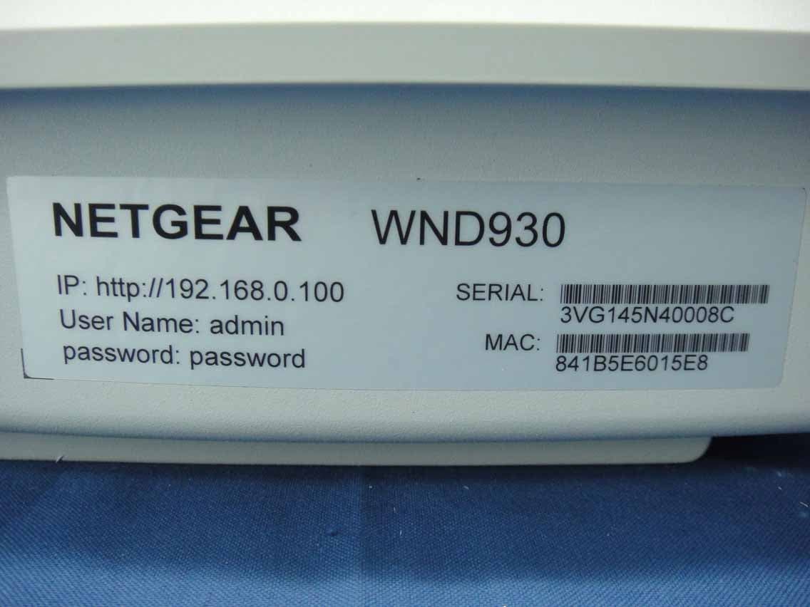
Click to zoom
Application Details
- Equipment Class
- NII - Unlicensed National Information Infrastructure TX
- Date of Grant
- Aug 27, 2014
- Application Purpose
- Original Equipment
- Date of Application
- Aug 27, 2014
- Equipment Note
- Outdoor High Power Wireless N Access Point
- Frequency Range
- 5180.00000000 - 5240.00000000
- Company
- Netgear Incorporated
- Country
- United States
Documents & Files
Document Text
Text extracted from the exhibit documents filed with the FCC. Open a document above to read the original.
Users Manual
Installation NETGEAR Outdoor High Power Wireless N Access Point WND930 Set Up the Access Point Before mounting the access point in a high location, first set up and test the unit to verify wireless network connectivity. Note: The access point has a DHCP client enabled by default. If a DHCP server exists in your network, the access point obtains an IP address from the DHCP server. If a DHCP server is not detected in your network after 30 seconds, the access point sets its IP address to a static IP address of 192.168.0.100. ¾To cable your access point: 1. Using an Ethernet cable, connect a power sourcing equipment (PSE) to a PoE port on the access point. Note: You must supply either AT power to at least one LAN port or AF power to two LAN ports to power the access point. You must supply AT power to both LAN ports to receive PoE power out. 2. If a DHCP server is not connected to your network, configure a computer with a static IP address of 192.168.0.210 and a subnet mask of 255.255.255.0. 3. Connect an Ethernet cable from a LAN port on the access point to a LAN port on the PC. 4. Check the LEDs to verify that the access point is set up correctly. Package Contents Unpack the box and verify the contents: • Outdoor High Power Wireless N Access Point • Wall mounting bracket • Four bracket screws • Two pole mount clamps • Three weatherproof cable glands LEDDescription Power LED•Off. Power is off. •Solid green. Power is on. •Amber, then blinking green. A self-test is running or software is being loaded. During startup, the LED is first steady amber, then goes off, and then blinks green before turning steady green after about 45 seconds. If after one minute the LED remains amber or continues to blink green, it indicates a system fault. Activity LED•Off. There is no network traffic through the access point. •Blinking green. There is network traffic through the access point. 2.4G WLAN LED •Off. The wireless interface is off. •Solid green. The wireless interface is on. •Blinking green. Wireless activity is detected on the 2.4G band. 5G WLAN LED•Off. The wireless interface is off. •Solid green. The wireless interface is on. •Blinking green. Wireless activity is detected on the 5G band. Heater LED•Off. Heater is off. •Solid green. Heater is on. LAN port LEDs•Off. No link is detected. •Solid green. Link is detected. •Solid amber. 10/100/1000 speed connection is detected. •Blinking amber. 10/100/1000 speed activity is detected. ¾To configure your access point for your network: 1. Connect to the access point by opening your browser and entering the access point’s IP address If a DHCP server is not installed in your network, the default IP address is 192.168.0.100. A login window displays. 2. Enter admin for the user name and password for the password, both in lower case letters. The access point user interface displays. 3. Select Configuration > System > Basic > General from the menu. August 2014 NETGEAR, Inc. 350 East Plumeria Drive San Jose, CA 95134, USA NETGEAR, the NETGEAR logo, and Connect with Innovation are trademarks and/or registered trademarks of NETGEAR, Inc. and/or its subsidiaries in the United States and/or other countries. Information is subject to change without notice. © NETGEAR, Inc. All rights reserved. 4. Complete the Access Point Name field and select your Country/ Region of operation from the drop-down list. 5. Select Configuration > IP > IP Settings from the menu and configure the IP settings for your network. Note: If you use DHCP, reserve an IP address (based on the access point’s MAC address) on the DHCP server. You can then use that address to log in to the access point. 6. Select Configuration > Wireless > Basic > Wireless Settings and configure the wireless settings for your network. For more information about wireless settings, see the reference manual. 7. Select Configuration > Security > Profile Settings and configure security profiles for your network. For more information about security profile settings, see the reference manual. Deploy the Access Point The best location for your access point is elevated such as wall or ceiling mounted, at the center of your wireless coverage area, and within line of sight of all mobile devices. ¾To deploy your access point: 1. Disconnect your access point and position it where you will deploy it. 2. Connect an ethernet cable from your access point to a LAN port on your router, switch or hub. 3. Connect a power sourcing equipment (PSE) to one of the PoE ports on the access point. If your router switch or hub supplies PoE, skip this step. Note: You must supply either AT power to at least one LAN port or AF power to two LAN ports to power the access point. You must supply AT power to both LAN ports to receive PoE power out. 4. Using a wireless device, verify connectivity by using a browser to connect to the Internet. ProblemCausePossible Solution You cannot access the Internet or the LAN from a wireless device. A configuration problem exists. •Make sure that the SSID and wireless security settings of the wireless device are the same as those of the access point. •The wireless device might not have the correct TCP/IP settings to communicate with the network. Restart the wireless device and check that TCP/IP is set up correctly for that network. •The access point default values might not work with your network. Check the access point default configuration against the configuration of other devices in your network. For information about changing the default values of the access point, see the reference manual. Support Thank you for selecting NETGEAR products. After installing your device, locate the serial number on the label of your product and use it to register your product at https://my.netgear.com. You must register your product before you can use NETGEAR telephone support. NETGEAR recommends registering your product through the NETGEAR website. For product updates and web support, visit http://support.netgear.com. NETGEAR recommends th…
Text truncated - open the document above for the full version.
Attestation Statements
NETGEAR, INC. 350 East Plumeria Drive, San Jose, CA 95134, USA Tel:408-890-3530/Fax:408-907-8097 Date: 2014/6/27 G E N E R A L D E C L A R A T I O N We, NETGEAR, INC. declare that the device does not support channel 12 ~ 13 in 2.4GHz band and any non- US channels in all the operational mode(s) for the following product. FCC ID: PY314200281 If you have any questions regarding the authorization, please don’t hesitate to contact us. Thank you! Signature: David Kay/ Regulatory Compliance Manager NETGEAR, INC. TEL: 4088903160 FAX: 4089078097 E-mail: [email protected]
Attestation Statements
NETGEAR, INC. 350 East Plumeria Drive, San Jose, CA 95134, USA Tel:408-890-3530/Fax:408-907-8097 P R O F E S S I O N A L I N S T A L LA T I O N A T T E S T A T I O N Date: 2014-08-27 FCC ID: PY314200281 To Whom It May Concern: Please be advised that due to the unique market and function of this product, this product will need special trained professional in configuring and installing the product. We hereby declare that the product will be distributed through controlled distribution channels which require a trained professional to install this product and will not be sold directly to the general public through retail stores. Sincerely yours, ----------------------------------- David Kay/ Regulatory Compliance Manager NETGEAR, INC. TEL: 408 890 3657 FAX: 408 907 8097 E-mail: [email protected]
Cover Letter(s)
NETGEAR, INC. 350 East Plumeria Drive, San Jose, CA 95134, USA Tel:408-890-3530/Fax:408-907-8097 Date: 2014/6/27 FCC ID: PY314200281 Federal Communications Commission Authorization and Evaluation Division Confidentiality Request Pursuant to Sections 0.457 and 0.459 of the Commission’s Rules, the Applicant hereby requests confidential treatment of information accompanying this Application as outlined below: Schematics Block Diagram The above materials contain trade secrets and proprietary information not customarily released to the public. The public disclosure of these matters might be harmful to the Applicant and provide unjustified benefits to its competitors. The Applicant understands that pursuant to Rule 0.457, disclosure of this Application and all accompanying documentation will not be made before the date of the Grant for this application. Sincerely yours, David Kay/ Regulatory Compliance Manager NETGEAR, INC. TEL: 4088903160 FAX: 4089078097 E-mail: [email protected]
Cover Letter(s)
NETGEAR, INC. 350 East Plumeria Drive, San Jose, CA 95134, USA Tel:408-890-3530/Fax:408-907-8097 Federal Communications Commission Authorization and Evaluation Division Date: June 27, 2014 Confidentiality Request FCC ID: PY314200281 Pursuant to Sections 0.457 and 0.459 of the commission’s rules, we request short-term confidential treatment for the following information until 180 days in order to ensure sensitive business information remains confidential until the actual marketing of the device: External photos Test Setup photos User’s manual Internal Photos Sincerely yours, ------------------------------------------------------- David Kay/ Regulatory Compliance Manager NETGEAR, INC. TEL: 4088903160 FAX: 4089078097 E-mail: [email protected]
Cover Letter(s)
NETGEAR, INC. 350 East Plumeria Drive, San Jose, CA 95134, USA Tel:408-890-3530/Fax:408-907-8097 P O W E R O F A T T O R N E Y Date: 2014/6/27 FCC ID: PY314200281 To whom it may concern: We, the undersigned, NETGEAR, INC. hereby authorize Bureau Veritas Consumer Products Services (H.K) Ltd., Taoyuan Branch. of Taiwan to act on our behalf in all matters relating to all processes required in the FCC Part 15C+15E approval and any communication needed with the national authority. Any and all acts carried out by Bureau Veritas Consumer Products Services (H.K) Ltd., Taoyuan Branch. on our behalf shall have the same effects as acts of our own. If you have any questions regarding the authorization, please don’t hesitate to Contact us. Thank you! Sincerely yours, Signature: David Kay/ Regulatory Compliance Manager NETGEAR, INC. TEL: 4088903160 FAX: 4089078097 E-mail: [email protected]
External Photos
Report No.: 140606E08 1 of 15 CONSTRUCTION PHOTOS OF EUT
ID Label/Location Info
SHEET: AUTHOR:TITLE: P/N: REV: THIS DOCUMENT AND THE DATA DISCLOSED HEREIN OR WHEREWITH IS NOT TO BE REPRODUCED, USED OR DISCLOSED IN WHOLE OR IN PART TO ANYONE WITHOUT THE PERMISSION OF NETGEAR, INC. REVDESCRIPTION OF REVISIONENG APPDDATE 02AW-12884-011 of 1 AW, WND930, PLBLM HUMPHREY 10MAR14R HUINITIAL DOCUMENT CREATION01 11AUG14M HUMPHREYCHANGED FC ID, PRODUCT NAME02 White Pantone Cool Grey 11C NOTE: 1. REFER TO NETGEAR SPEC. DOC-00093 FOR COLOR TOLERANCES. 2. INK COLOR IS SHOWN TO THE RIGHT. 3. PART OUTLINE IS MAGENTA COLOR AND DOES NOT PRINT. 4. THE MATERIALS AND PROCESS USED TO FABRICATE THIS PART ARE TO BE CONSISTENT WITH THE EU DIRECTIVE 2002/95/EC, RESTRICTION OF HAZARDOUS SUBSTANCES IN ELECTRICAL AND ELECTRONIC EQUIPMENT (RoHS). THE FINISHED PART TO BE ACCOMPANIED BY A SIGNED CERTIFICATE OF COMPLIANCE TO DIRECTIVE 2002/95/EC. 2.4GHz2.4GHz WND930 PLACE LABEL AT LOCATION SHOWN (Fig. 1) FCC ID: PY314200281 FCC LABEL LOCATION The label will be permanently affixed at a conspicuous location on the device. Label
Internal Photos
Report No.: 140606E08 2 of 15 Report No.: 140606E08 3 of 15 Report No.: 140606E08 4 of 15 Report No.: 140606E08 5 of 15 Report No.: 140606E08 6 of 15 Report No.: 140606E08 7 of 15 Report No.: 140606E08 8 of 15 Report No.: 140606E08 9 of 15 Report No.: 140606E08 10 of 15 Rev 1.0 Report No.: 140606E08 11 of 15 Report No.: 140606E08 12 of 15 Report No.: 140606E08 13 of 15 Report No.: 140606E08 14 of 15 Report No.: 140606E08 15 of 15
Operational Description
FCC ID: PY314200281 Report No.: RF140606E08 Operational Description This device is a Outdoor High Power Wireless N Access Point, which operates in both of the 5GHz and 2.4GHz bands and can transmitting simultaneously, the maximum data rate could be up to 300Mbps which OFDM technique. If the signal to noise radio is too poor which could not support 300Mbps, the 11Mbps data rate with DSSS technique will be applied. The transmitter of the EUT is powered by 48Vdc (from POE). The antennas provided to the EUT, please refer to the following table: The other instruction, please have a look at the users manual. FCC 15.407(c) states: The device shall automatically discontinue transmission in case of either absence of information to transmit or operational failure. These provisions are not intended to preclude the transmission of control or signaling information or the use of repetitive codes used by certain digital technologies to complete frame or burst intervals. Applicants shall include in their application for equipment authorization a description of how this requirement is met” Data transmission is always initiated by software, which is then pass down through the MAC, through the digital and analog baseband, and finally to the RF chip. Several special packets (ACKs, CTS, PSPoll, etc...) are initiated by the MAC. There are the only ways the digital baseband portion will turn on the RF transmitter, which it then turns off at the end of the packet. Therefore, the transmitter will be on only while one of the aforementioned packets are being transmitted.
RF Exposure Info
Report No.: SA140606E08 1 of 7 Report Format Version 5.0.1 Reference No.: RF EXPOSURE REPORT REPORT NO.: SA140606E08 MODEL NO.: WND930 FCC ID: PY314200281 RECEIVED: June 06, 2014 TESTED: Aug. 07, 2014 ISSUED: Aug. 20, 2014 APPLICANT: Netgear Incorporated ADDRESS: 350 East Plumeria Drive San Jose, CA 95134 ISSUED BY: Bureau Veritas Consumer Products Services (H.K.) Ltd., Taoyuan Branch Hsin Chu Laboratory LAB ADDRESS: No. 81-1, Lu Liao Keng, 9th Ling,Wu Lung Tsuen, Chiung Lin Hsiang, Hsin Chu Hsien 307, Taiwan, R.O.C. This report should not be used by the client to claim product certification, approval, or endorsement by any government agencies. This report is for your exclusive use. Any copying or replication of this report to or for any other person or entity, or use of our name or trademark, is permitted only with our prior written permission. This report sets forth our findings solely with respect to the test samples identified herein. The results set forth in this report are not indicative or representative of the quality or characteristics of the lot from which a test sample was taken or any similar or identical product unless specifically and expressly noted. Our report includes all of the tests requested by you and the results thereof based upon the information that you provided to us. You have 60 days from date of issuance of this report to notify us of any material error or omission caused by our negligence, provided, however, that such notice shall be in writing and shall specifically address the issue you wish to raise. A failure to raise such issue within the prescribed time shall constitute your unqualified acceptance of the completeness of this report, the tests conducted and the correctness of the report contents. Unless specific mention, the uncertainty of measurement has been explicitly taken into account to declare the compliance or non-compliance to the specification Report No.: SA140606E08 2 of 7 Report Format Version 5.0.1 Reference No.: TABLE OF CONTENTS RELEASE CONTROL RECORD ..................................................................................... 3 1. CERTIFICATION ...................................................................................................... 4 2. RF EXPOSURE LIMIT ............................................................................................. 5 3. MPE CALCULATION FORMULA ............................................................................. 5 4. CLASSIFICATION .................................................................................................... 5 5. ANTENNA GAIN ...................................................................................................... 6 6. CALCULATION RESULT OF MAXIMUM CONDUCTED POWER .......................... 7 Report No.: SA140606E08 3 of 7 Report Format Version 5.0.1 Reference No.: RELEASE CONTROL RECORD ISSUE NO. REASON FOR CHANGE DATE ISSUED SA140606E08 Original release Aug. 20, 2014 Report No.: SA140606E08 4 of 7 Report Format Version 5.0.1 Reference No.: 1. CERTIFICATION PRODUCT: Outdoor High Power Wireless N Access Point BRAND NAME: NETGEAR MODEL NO.: WND930 TEST SAMPLE: ENGINEERING SAMPLE APPLICANT: Netgear Incorporated TESTED DATE: Aug. 07, 2014 STANDARDS: FCC Part 2 (Section 2.1091) KDB 447498 D03 IEEE C95.1 The above equipment (Model: WND930) has been tested by Bureau Veritas Consumer Products Services (H.K.) Ltd., Taoyuan Branch, and found compliance with the requirement of the above standards. The test record, data evaluation & Equipment Under Test (EUT) configurations represented herein are true and accurate accounts of the measurements of the sample’s EMC characteristics under the conditions specified in this report. PREPARED BY : , DATE: Aug. 20, 2014 ( Lori Chung, Specialist ) APPROVED BY : , DATE:Aug. 20, 2014 ( May Chen, Manager ) Report No.: SA140606E08 5 of 7 Report Format Version 5.0.1 Reference No.: 2. RF EXPOSURE LIMIT LIMITS FOR MAXIMUM PERMISSIBLE EXPOSURE (MPE) FREQUENCY RANGE (MHz) ELECTRIC FIELD STRENGTH (V/m) MAGNETIC FIELD STRENGTH (A/m) POWER DENSITY (mW/cm 2 ) AVERAGE TIME (minutes) LIMITS FOR GENERAL POPULATION / UNCONTROLLED EXPOSURE 300-1500 ... ... F/1500 30 1500-100,000 ... ... 1.0 30 F = Frequency in MHz 3. MPE CALCULATION FORMULA Pd = (Pout*G) / (4*pi*r 2 ) where Pd = power density in mW/cm 2 Pout = output power to antenna in mW G = gain of antenna in linear scale pi = 3.1416 r = distance between observation point and center of the radiator in cm 4. CLASSIFICATION The antenna of this product, under normal use condition, is at least 26cm away from the body of the user. So, this device is classified as Mobile Device. Report No.: SA140606E08 6 of 7 Report Format Version 5.0.1 Reference No.: 5. ANTENNA GAIN The antennas provided to the EUT, please refer to the following table: Internal Antenna Transmitter Circuit Antenna Gain(dBi) Including cable loss Frequency rangeAntenna Type Connecter Type Chain (0) 5 2.4~2.4835GHz Panel i-pex(MHF) Chain (1) 5 Panel i-pex(MHF) Chain (0) 5 5.150~5.850GHz Panel i-pex(MHF) Chain (1) 5 Panel i-pex(MHF) External Antenna Transmitter Circuit Antenna Gain(dBi) Including cable loss Frequency rangeAntenna Type Connecter Type Chain (0) 5 2.4~2.4835GHz Dipole N type(M) Chain (1) 5 Dipole N type(M) Chain (0) 7 5.150~5.850GHz Dipole N type(M) Chain (1) 7 Dipole N type(M) Report No.: SA140606E08 7 of 7 Report Format Version 5.0.1 Reference No.: 6. CALCULATION RESULT OF MAXIMUM CONDUCTED POWER 15.247(2.4GHz): FREQUENCY (MHz) MAX POWER (mW) ANTENNA GAIN (dBi) DISTANCE (cm) POWER DENSITY (mW/ cm 2 ) LIMIT (mW/cm 2 ) 2412 ~ 2462 474.558 8.01 26 0.35329 1 Note: Directional gain = 5dBi + 10log(2) = 8.01dBi. 15.247(5GHz): FREQUENCY (MHz) MAX POWER (mW) ANTENNA GAIN (dBi) DISTANCE (cm) POWER DENSITY (mW/ cm 2 ) LIMIT (mW/cm 2 ) 5745 ~ 5825 507.064 10.01 26 0.59828 1 Note: Directional gain = 7dBi + 10log(2) = 10.01dBi. 15.407(5GHz): FREQUENCY (MHz) MAX POWER (mW) ANTENNA GAIN (dBi) DISTANCE (cm) POWER DENSITY (m…
Text truncated - open the document above for the full version.
Test Report
Report No.: RF140606E08 1 of 131 Report Format Version 5.2.1 FCC TEST REPORT (15.247) REPORT NO.: RF140606E08 MODEL NO.: WND930 FCC ID: PY314200281 RECEIVED: June 06, 2014 TESTED: June 18 to Aug. 07, 2014 ISSUED: Aug. 20, 2014 APPLICANT: Netgear Incorporated ADDRESS: 350 East Plumeria Drive San Jose, CA 95134 ISSUED BY: Bureau Veritas Consumer Products Services (H.K.) Ltd., Taoyuan Branch Hsin Chu Laboratory LAB ADDRESS : No. 81-1, Lu Liao Keng, 9th Ling, Wu Lung Tsuen, Chiung Lin Hsiang, Hsin Chu Hsien 307, Taiwan, R.O.C. TEST LOCATION (1): No. 81-1, Lu Liao Keng, 9th Ling, Wu Lung Tsuen, Chiung Lin Hsiang, Hsin Chu Hsien 307, Taiwan, R.O.C. TEST LOCATION (2): No. 49, Ln. 206, Wende Rd., Shangshan Tsuen, Chiung Lin Hsiang, Hsin Chu Hsien 307, Taiwan, R.O.C. This report should not be used by the client to claim product certification, approval, or endorsement by TAF or any government agencies. This report is for your exclusive use. Any copying or replication of this report to or for any other person or entity, or use of our name or trademark, is permitted only with our prior written permission. This report sets forth our findings solely with respect to the test samples identified herein. The results set forth in this report are not indicative or representative of the quality or characteristics of the lot from which a test sample was taken or any similar or identical product unless specifically and expressly noted. Our report includes all of the tests requested by you and the results thereof based upon the information that you provided to us. You have 60 days from date of issuance of this report to notify us of any material error or omission caused by our negligence, provided, however, that such notice shall be in writing and shall specifically address the issue you wish to raise. A failure to raise such issue within the prescribed time shall constitute your unqualified acceptance of the completeness of this report, the tests conducted and the correctness of the report contents. Unless specific mention, the uncertainty of measurement has been explicitly taken into account to declare the compliance or non-compliance to the specification Report No.: RF140606E08 2 of 131 Report Format Version 5.2.1 Table of Contents RELEASE CONTROL RECORD .......................................................................................... 5 1. CERTIFICATION ...................................................................................................... 6 2. SUMMARY OF TEST RESULTS .............................................................................. 7 2.1 MEASUREMENT UNCERTAINTY ........................................................................... 8 3. GENERAL INFORMATION ....................................................................................... 9 3.1 GENERAL DESCRIPTION OF EUT ......................................................................... 9 3.2 DESCRIPTION OF TEST MODES ......................................................................... 12 3.2.1 TEST MODE APPLICABILITY AND TESTED CHANNEL DETAIL ......................... 13 3.3 GENERAL DESCRIPTION OF APPLIED STANDARDS ........................................ 16 3.4 DUTY CYCLE OF TEST SIGNAL ........................................................................... 17 3.5 DESCRIPTION OF SUPPORT UNITS ................................................................... 19 3.6 CONFIGURATION OF SYSTEM UNDER TEST .................................................... 20 4. TEST TYPES AND RESULTS (fOR 2.4GHz, 2.400 ~ 2.4835GHz Band) .............. 23 4.1 CONDUCTED EMISSION MEASUREMENT ......................................................... 23 4.1.1 LIMITS OF CONDUCTED EMISSION MEASUREMENT....................................... 23 4.1.2 TEST INSTRUMENTS ........................................................................................... 23 4.1.3 TEST PROCEDURES ............................................................................................ 24 4.1.4 DEVIATION FROM TEST STANDARD .................................................................. 24 4.1.5 TEST SETUP ......................................................................................................... 24 4.1.6 EUT OPERATING CONDITIONS ........................................................................... 25 4.1.7 TEST RESULTS (MODE 2) .................................................................................... 26 4.2 RADIATED EMISSION AND BANDEDGE MEASUREMENT ................................. 30 4.2.1 LIMITS OF RADIATED EMISSION AND BANDEDGE MEASUREMENT .............. 30 4.2.2 TEST INSTRUMENTS ........................................................................................... 31 4.2.3 TEST PROCEDURES ............................................................................................ 33 4.2.4 DEVIATION FROM TEST STANDARD .................................................................. 34 4.2.5 TEST SETUP ......................................................................................................... 34 4.2.6 EUT OPERATING CONDITIONS ........................................................................... 34 4.2.7 TEST RESULTS (MODE 1) .................................................................................... 35 4.2.8 TEST RESULTS (MODE 2) .................................................................................... 48 4.3 6dB BANDWIDTH MEASUREMENT ..................................................................... 61 4.3.1 LIMITS OF 6dB BANDWIDTH MEASUREMENT ................................................... 61 4.3.2 TEST INSTRUMENTS ........................................................................................... 61 4.3.3 TEST PROCEDURE .............................................................................................. 61 4.3.4 DEVIATION FROM TEST STANDARD .................................................................. 61 4.3.5 TEST SETUP …
Text truncated - open the document above for the full version.
Test Report
Report No.: RF140606E08-1 1 of 70 Report Format Version 5.2.1 FCC TEST REPORT (15.407) REPORT NO.: RF140606E08-1 MODEL NO.: WND930 FCC ID: PY314200281 RECEIVED: June 06, 2014 TESTED: June 20 to Aug. 06, 2014 ISSUED: Aug. 20, 2014 APPLICANT: Netgear Incorporated ADDRESS: 350 East Plumeria Drive San Jose, CA 95134 ISSUED BY: Bureau Veritas Consumer Products Services (H.K.) Ltd., Taoyuan Branch Hsin Chu Laboratory LAB ADDRESS : No. 81-1, Lu Liao Keng, 9th Ling, Wu Lung Tsuen, Chiung Lin Hsiang, Hsin Chu Hsien 307, Taiwan, R.O.C. TEST LOCATION (1): No. 81-1, Lu Liao Keng, 9th Ling, Wu Lung Tsuen, Chiung Lin Hsiang, Hsin Chu Hsien 307, Taiwan, R.O.C. TEST LOCATION (2): No. 49, Ln. 206, Wende Rd., Shangshan Tsuen, Chiung Lin Hsiang, Hsin Chu Hsien 307, Taiwan, R.O.C. This report should not be used by the client to claim product certification, approval, or endorsement by TAF or any government agencies. This report is for your exclusive use. Any copying or replication of this report to or for any other person or entity, or use of our name or trademark, is permitted only with our prior written permission. This report sets forth our findings solely with respect to the test samples identified herein. The results set forth in this report are not indicative or representative of the quality or characteristics of the lot from which a test sample was taken or any similar or identical product unless specifically and expressly noted. Our report includes all of the tests requested by you and the results thereof based upon the information that you provided to us. You have 60 days from date of issuance of this report to notify us of any material error or omission caused by our negligence, provided, however, that such notice shall be in writing and shall specifically address the issue you wish to raise. A failure to raise such issue within the prescribed time shall constitute your unqualified acceptance of the completeness of this report, the tests conducted and the correctness of the report contents. Unless specific mention, the uncertainty of measurement has been explicitly taken into account to declare the compliance or non-compliance to the specification Report No.: RF140606E08-1 2 of 70 Report Format Version 5.2.1 Table of Contents RELEASE CONTROL RECORD .......................................................................................... 4 1. CERTIFICATION ...................................................................................................... 5 2. SUMMARY OF TEST RESULTS .............................................................................. 6 2.1 MEASUREMENT UNCERTAINTY ........................................................................... 7 3. GENERAL INFORMATION ....................................................................................... 8 3.1 GENERAL DESCRIPTION OF EUT ......................................................................... 8 3.2 DESCRIPTION OF TEST MODES ......................................................................... 10 3.2.1 TEST MODE APPLICABILITY AND TESTED CHANNEL DETAIL ......................... 11 3.3 GENERAL DESCRIPTION OF APPLIED STANDARDS ........................................ 13 3.4 DUTY CYCLE OF TEST SIGNAL ........................................................................... 14 3.5 DESCRIPTION OF SUPPORT UNITS ................................................................... 17 3.6 CONFIGURATION OF SYSTEM UNDER TEST .................................................... 18 4. TEST TYPES AND RESULTS ................................................................................ 21 4.1 CONDUCTED EMISSION MEASUREMENT ......................................................... 21 4.1.1 LIMITS OF CONDUCTED EMISSION MEASUREMENT....................................... 21 4.1.2 TEST INSTRUMENTS ........................................................................................... 21 4.1.3 TEST PROCEDURES ............................................................................................ 22 4.1.4 DEVIATION FROM TEST STANDARD .................................................................. 22 4.1.5 TEST SETUP ......................................................................................................... 22 4.1.6 EUT OPERATING CONDITIONS ........................................................................... 23 4.1.7 TEST RESULTS (MODE 2) .................................................................................... 24 4.2 RADIATED EMISSION AND BANDEDGE MEASUREMENT ................................. 28 4.2.1 LIMITS OF RADIATED EMISSION AND BANDEDGE MEASUREMENT .............. 28 4.2.2 LIMITS OF UNWANTED EMISSION OUT OF THE RESTRICTED BANDS .......... 28 4.2.3 TEST INSTRUMENTS ........................................................................................... 29 4.2.4 TEST PROCEDURES ...............…
Text truncated - open the document above for the full version.
Contact Information
Applicant
David Kay
Test Firm
Bureau Veritas CPS (H.K.) Ltd., Taoyuan BranchRichard Chen
Technical Specifications
| # | Rule Parts | Frequency Range | Power Output |
|---|---|---|---|
| 1 | 15E | 5.18 GHz - 5.24 GHz | 36.00 mW |
Other Applications from Netgear Incorporated

PY325100647
Aug 04, 2026BE5000 Dual-Band PoE 2.5G Insight Managed WiFi 7 Outdoor Access Point
Equipment Class
DTS - Digital Transmission SystemPY325300652
May 12, 2026BE5000 Dual-Band PoE 2.5G Insight Managed WiFi 7 Access Point
Equipment Class
NII - Unlicensed National Information Infrastructure TXPY325400656
Apr 16, 2026Orbi Outdoor Satellite
Equipment Class
DTS - Digital Transmission SystemPY324400640
Dec 12, 2025Orbi 11BE WiFi 7 Tri-band Router, Orbi 11BE WiFi 7 Tri-band Satellite
Equipment Class
NII - Unlicensed National Information Infrastructure TXPY324100618
Jul 31, 2024Nighthawk 5G Mobile Router
Equipment Class
PCB - PCS Licensed Transmitter