PY3CG814WWireless Cable Modem/Router
Netgear Incorporated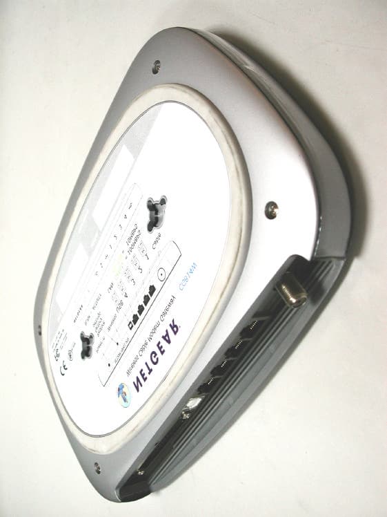
Click to zoom
Application Details
- Equipment Class
- DTS - Digital Transmission System
- Date of Grant
- Dec 25, 2002
- Application Purpose
- Original Equipment
- Date of Application
- Dec 25, 2002
- Equipment Note
- Wireless Cable Modem/Router
- Frequency Range
- 2412.00000000 - 2462.00000000
- Company
- Netgear Incorporated
- Country
- United States
Documents & Files
Document Text
Text extracted from the exhibit documents filed with the FCC. Open a document above to read the original.
Users Manual
Netgear CG814W Wireless Cable Modem Gateway Netgear CG814W Wireless Cable Modem Gateway Quick Guide COPYRIGHT & TRADEMARKS Copyright 2002 Netgear, All Rights Reserved. Microsoft, Windows, and the Windows logo are registered trademarks of Microsoft Corporation. All other trademarks and brand names are the property of their respective proprietors. FCC STATEMENT The Netgear CG814W has been tested and complies with the specifications for a Class B digital device, pursuant to Part 15 of the FCC Rules. These limits are designed to provide reasonable protection against harmful interface in a residential installation. This equipment generates, uses, and can radio frequency energy and, if not installed and used according to the instructions, may cause harmful interference to radio communications. However, there is no guarantee that interference will not occur in a particular installation. If this equipment does cause harmful interference to radio or television reception, which is found by turning the equipment off and on, the user is encouraged to try to correct the interference by one or more of the following measure: • Reorient or relocate the receiving antenna • Increase the separation between the equipment of devices • Connect the equipment to an outlet other than the receiver • Consult a dealer or an experienced radio/TV technician for assistance 0 Netgear CG814W Wireless Cable Modem Gateway Table of Contents 1 Netgear CG814W Wireless Cable Modem Gateway Chapter 1: Introduction Overview Thank you for purchasing the Netgear CG814W Wireless Cable Modem Gateway. The Netgear CG814W provides the ideal solution for connecting your wireless network to a high-speed broadband Internet connection and a 10/100 Fast Ethernet backbone. Configurable as a DHCP server for your existing network, the Netgear CG814W acts as the only externally recognized Internet gateway on your local area network (LAN) and serve as an Internet NAT firewall against unwanted outside intruders. The Netgear CG814W can also be configured to filter internal users’ access to the Internet. A typical gateway relies on a hub or a switch to share its Internet connection, but the Netgear CG814W channels this connection through the blazing, full duplex of its built-in 10/100 4-Port Switch. This cutting-edge combination of wireless router and switch technology eliminates the need to buy an additional hub or switch and extends the range of your wireless network. Now your entire wireless network can enjoy blazing broadband Internet connections supported by its robust switched backbone. With the dual-function speed and power of the Netgear CG814W, your network will take off at speeds faster than you ever imagined possible. Software Features DOCSIS Features z Cable Modem (CM) is 1.0 and 1.1 upgradeable z Concatenation, Fragmentation, Payload Header suppression, IGMP and BPI and BPI Plus are supported features for DOCSIS 1.1 z 4/16/32/64/128/256/512/1024 QAM Downstream Receiver z 2/4/8/16/32/64/128/256 QAM Advanced TDMA Upstream Transmitter z Both IP and LLC filters are supported z Sixteen (16) destination address filters and 256 multicast/unicast DA filters z Sixteen (16) independent upstream queues for multiple QoS support 2 Netgear CG814W Wireless Cable Modem Gateway USB Features z OS (Win2K, XP, WinME) supported for USB interface Wireless Features z Supports at least one beacon/DTIM interval of within the range 20-1000 κμ s z Supports reception of fragmented packets z Supports reception of RTS and generation of CTS Firewall Features z Stateful Packet Inspection against both Denial of Service and Distributed Denial of Service attacks and will protect against the following: ¾ Reassembly attacks ¾ SYN Attack (SYN Flood) ¾ ICMP Flood ¾ Ping of Death Attack ¾ Tear Drop Attack ¾ IP Spoofing Attack ¾ LAND Attack ¾ Jolt ¾ Winnuke Attack (Netbios out-of-bound) ¾ OverDrop ¾ BONK, BOINK ¾ Blind Spoofing ¾ Echo/Chargen ¾ Storm ¾ Smurf Attack ¾ Mime Flood z De-Militarized Zone (DMZ) which allows a computer on the LAN to expose all of its ports to the WAN that are not otherwise filtered z Logged Events which all security incidents will be logged z Keyword blocking is based on keywords in a URL and can be specified by the user 3 Netgear CG814W Wireless Cable Modem Gateway NAT Requirements The implementation of NAT must allow for specific port redirection. Listed below are applications supported. ¾ FTP ¾ IRC ¾ H.323 ¾ Quake ¾ Blizzard games ¾ Chat ALG ¾ Real Audio/Video ¾ CUSEEME ¾ Netmeeting ¾ MS Games but not with game zone ¾ DIABOLO II ¾ Activision Games ¾ PCAnywhere ¾ SSL ¾ NNTP z Port Forwarding, incoming traffic that is not part of an existing connection will be dropped unless the user specifies forwarding of the server to a host on the LAN Virtual Private Network (VPN) Feature z Having the ability to enable or disable PPTP and IPSec pass through Minimum Requirements One RJ-45 Broadband Internet connection, with a Cable Modem f f f f f f One PC with an installed 10Mbps, 100Mbps, or 10/100 Mbps Ethernet card (optional) TCP/IP network protocol for each PC UTP network cable with RJ-45 connector Microsoft Internet Explorer 4.0 or later, or Netscape Navigator 4.0 or later. (5.0 and 4.7, respectively, are strongly recommended.) Windows 95, 98, Millennium, NT 4.0, 2000 or XP Package Contents 4 Netgear CG814W Wireless Cable Modem Gateway 5 {1} Cable Modem 5 {1} AC Power adapter 5 {1} CAT.5 Ethernet cable {RJ-45} 5 {1} USB cable 5 {1} User’s Manual 5 Netgear CG814W Wireless Cable Modem Gateway Chapter 2: Using the Netgear CG814W All interface and status LEDs are provided on the front panel. The power connectors, signal connectors, and Restore Factory Defaults/Reboot button are on the rear panel. The Netgear CG814W’s Rear Panel The rear panel of the Netgear CG814W is where all of the device’s connections are made. Power-in The Power Port is where you will connect the included AC Power adapter. USB The USB Port. You can connect the Gateway to PC using USB line.…
Text truncated - open the document above for the full version.
Block Diagram
A A B B C C D D E E 44 33 22 11 (BCM3360) Block Diagram CPU/MAC/PHY ACM6264-H -Cable Modem Reference Design 10/100baseT (Port 1) US TUNER DS JTAG Port and Reset Control SDRAM 8MB/16MB/32MB (BCM3415/BCM3401) USB Upstream Port POWER SUPPLY 12VDC Wall Transformer +1.8V+3.3V LED's FLASH 4MB/8MB/16MB MII EPHY INTERFACE UART INTERFACE EBI INTERFACE HPNA INTERFACE HPNA RJ11 HPNA AFE (BCM4100) EPHY SWITCH (BCM5325M) 10/100baseT (Port 2) 10/100baseT (Port 3) 10/100baseT (Port 4) WIRELESS 802.11 MODULE DIPLEXER AND
ID Label/Location Info
LABEL Format: This device complies with Part 15 of the FCC Rules Operation is subject to the following two conditions: (1) This device may not cause harmful interference, and (2) This device must accept any interference received, including interference that may cause undesired operation FCC ID: (with optional Tx, FCC ID: PD5LMWP200) LABEL Position: Tested to Comply With FCC Standard FOR HOME OR OFFICE USE PY3CG814W LABEL LABEL
Test Report
Test Report ------------------------------------------------------------------------------ 3/47 Report No.: N1015722 Training Research Co., Ltd., TEL: 886-2-26935155, Fax: 886-2-26934440 Tables of Contents I. GENERAL ..................................................................................................................... 5 1.1 Introduction .............................................................................................................. 5 1.2 Description of EUT .................................................................................................. 5 1.3 Description of Support Equipment ........................................................................... 6 1.4 Configuration of System Under Test ........................................................................ 9 1.5 Verify the Frequency and Channel .......................................................................... 13 1.6 Test Procedure ........................................................................................................ 14 1.7 Location of the Test Site ......................................................................................... 14 1.8 General Test Condition ........................................................................................... 14 II. Section 15.101(a) : Equipment Authorization of Unintentional Radiators................ 15 III. Section 15.203 : Antenna Requirement........................................................................ 16 IV. Section 15.207 : Power Line Conducted Emissions for AC Powered Units ............. 17 4.1 Test Condition & Setup ........................................................................................... 17 4.2 List of Test Instruments ........................................................................................... 17 4.3 Test Configuration .................................................................................................. 18 4.4 Test Result of Conducted Emissions ....................................................................... 19 V. Section 15.247(a) : Technical Description of the EUT................................................. 20 VI. Section 15.247(a)(2) : Bandwidth for Direct Sequence System ................................. 21 6.1 Test Condition & Setup ........................................................................................... 21 6.2 Test Instruments Configuration ............................................................................... 21 6.3 List of Test Instruments ........................................................................................... 21 6.4 Test Result of Bandwidth ......................................................................................... 22 VII. Section 15.247(b) : Power Output ............................................................................... 26 7.1 Test Condition & Setup ........................................................................................... 26 7.2 List of Test Instruments ........................................................................................... 27 7.3 Test Result .............................................................................................................. 27 Test Report ------------------------------------------------------------------------------ 4/47 Report No.: N1015722 Training Research Co., Ltd., TEL: 886-2-26935155, Fax: 886-2-26934440 VIII. Section 15.247(c) : Spurious Emissions (Radiated) ................................................. 28 8.1 Test Condition & Setup ........................................................................................... 28 8.2 List of Test Instruments ........................................................................................... 29 8.3 Test Instruments Configuration ............................................................................... 30 8.4 Test Result of Spurious Radiated Emissions ........................................................... 32 8.5 Test Result of Bandedge........................................................................................... 37 IX. Section 15.247(d) : Power Spectral Density ................................................................ 40 9.1 Test Condition & Setup ........................................................................................... 40 9.2 Test Instruments Configuration ............................................................................... 40 9.3 List of Test Instruments............................................................................................ 40 9.4 Test Result of Power Spectral Density .................................................................... 41 X. Output Signal Test ......................................................................................................... 45 10.1 Test Condition & Setup ........................................................................................ 45 10.2 Test Configuration of Output Signal Test............................................................... 45 10.3 Output Signal Test Result....................................................................................... 46 Appendix A: Set Up Procedure .......................................................................................... 47 Test Report ------------------------------------------------------------------------------ 5/47 Report No.: N1015722 Training Research Co., Ltd., TEL: 886-2-26935155, Fax: 886-2-26934440 . GENERAL 1.1 Introduction The following measurement report is submitted on behalf of applicant in support that the cable gateway certification in accordance with Part 2 Subpart J and Part 15 Subpart A and C of the Commission's Rules and Regulations. 1.2 Description of EUT EUT : Wireless Cable Modem Gateway Model No. : CG814W Granted FCC ID : PY3CG814W Frequency Range : 2.412 GHz ~ 2.462GHz Support Channel : 11 Channel Modulation Sk…
Text truncated - open the document above for the full version.
Test Setup Photos
Test Setup Photos ------------------------------------------------------------------------- 1/3 FCC ID: PY3CG814W Training Research Co., Ltd., TEL: 886-2-26935155, Fax: 886-2-26934440 Conducted Test Setup Placement: (Photographs) Test Setup Photos ------------------------------------------------------------------------- 2/3 FCC ID: PY3CG814W Training Research Co., Ltd., TEL: 886-2-26935155, Fax: 886-2-26934440 Radiated Test Setup Placement: (Unintentional) Test Setup Photos ------------------------------------------------------------------------- 3/3 FCC ID: PY3CG814W Training Research Co., Ltd., TEL: 886-2-26935155, Fax: 886-2-26934440 Radiated Test Setup Placement: (Intentional)
Contact Information
Applicant
David Kay
Technical Contact
Training Research Co. Ltd.Eric Wong
[email protected]+886 2 26935155
255 Nanyang Street · Taipei · Taiwan
Test Firm
Training Research Co., Ltd.Jack Tsai
Technical Specifications
| # | Rule Parts | Frequency Range | Power Output |
|---|---|---|---|
| 1 | 15C | 2.41 GHz - 2.46 GHz | 31.00 mW |
Other Applications from Netgear Incorporated

PY325100647
Aug 04, 2026BE5000 Dual-Band PoE 2.5G Insight Managed WiFi 7 Outdoor Access Point
Equipment Class
DTS - Digital Transmission SystemPY325300652
May 12, 2026BE5000 Dual-Band PoE 2.5G Insight Managed WiFi 7 Access Point
Equipment Class
NII - Unlicensed National Information Infrastructure TXPY325400656
Apr 16, 2026Orbi Outdoor Satellite
Equipment Class
DTS - Digital Transmission SystemPY324400640
Dec 12, 2025Orbi 11BE WiFi 7 Tri-band Router, Orbi 11BE WiFi 7 Tri-band Satellite
Equipment Class
NII - Unlicensed National Information Infrastructure TXPY324100618
Jul 31, 2024Nighthawk 5G Mobile Router
Equipment Class
PCB - PCS Licensed Transmitter