PY3FWAG114Broadband ProSafe Dual-Band Wireless VPN Firewall
Netgear Incorporated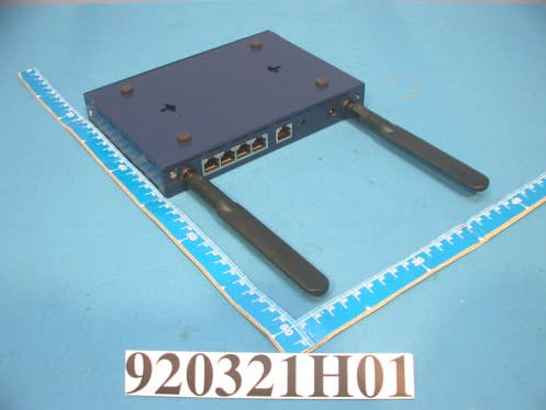
Click to zoom
Application Details
- Equipment Class
- NII - Unlicensed National Information Infrastructure TX
- Date of Grant
- May 29, 2003
- Application Purpose
- Original Equipment
- Date of Application
- May 29, 2003
- Equipment Note
- Broadband ProSafe Dual-Band Wireless VPN Firewall
- Frequency Range
- 5760.00000000 - 5800.00000000
- Company
- Netgear Incorporated
- Country
- United States
Documents & Files
Document Text
Text extracted from the exhibit documents filed with the FCC. Open a document above to read the original.
Users Manual
SM-FWAG114NA-0 Version 1.0 March 2003 NETGEAR, Inc. 4500 Great America Parkway Santa Clara, CA 95054 USA Reference Manual for the Model FWAG114 Cable/ DSL Wireless ProSafe Firewall ii © 2002 by NETGEAR, Inc. All rights reserved. Trademarks NETGEAR is a trademark of Netgear, Inc. Microsoft, Windows, and Windows NT are registered trademarks of Microsoft Corporation. Other brand and product names are registered trademarks or trademarks of their respective holders. Statement of Conditions In the interest of improving internal design, operational function, and/or reliability, NETGEAR reserves the right to make changes to the products described in this document without notice. NETGEAR does not assume any liability that may occur due to the use or application of the product(s) or circuit layout(s) described herein. Federal Communications Commission (FCC) Compliance Notice: Radio Frequency Notice This equipment has been tested and found to comply with the limits for a Class B digital device, pursuant to part 15 of the FCC Rules. These limits are designed to provide reasonable protection against harmful interference in a residential installation. This equipment generates, uses, and can radiate radio frequency energy and, if not installed and used in accordance with the instructions, may cause harmful interference to radio communications. However, there is no guarantee that interference will not occur in a particular installation. If this equipment does cause harmful interference to radio or television reception, which can be determined by turning the equipment off and on, the user is encouraged to try to correct the interference by one or more of the following measures: •Reorient or relocate the receiving antenna. •Increase the separation between the equipment and receiver. •Connect the equipment into an outlet on a circuit different from that to which the receiver is connected. •Consult the dealer or an experienced radio/TV technician for help. EN 55 022 Declaration of Conformance This is to certify that the Model FWAG114 Cable/DSL Wireless ProSafe Firewall is shielded against the generation of radio interference in accordance with the application of Council Directive 89/336/EEC, Article 4a. Conformity is declared by the application of EN 55 022 Class B (CISPR 22). iii Bestätigung des Herstellers/Importeurs Es wird hiermit bestätigt, daß das Model FWAG114 Cable/DSL Wireless ProSafe Firewall gemäß der im BMPT-AmtsblVfg 243/1991 und Vfg 46/1992 aufgeführten Bestimmungen entstört ist. Das vorschriftsmäßige Betreiben einiger Geräte (z.B. Testsender) kann jedoch gewissen Beschränkungen unterliegen. Lesen Sie dazu bitte die Anmerkungen in der Betriebsanleitung. Das Bundesamt für Zulassungen in der Telekommunikation wurde davon unterrichtet, daß dieses Gerät auf den Markt gebracht wurde und es ist berechtigt, die Serie auf die Erfüllung der Vorschriften hin zu überprüfen. Certificate of the Manufacturer/Importer It is hereby certified that the Model FWAG114 Cable/DSL Wireless ProSafe Firewall has been suppressed in accordance with the conditions set out in the BMPT-AmtsblVfg 243/1991 and Vfg 46/1992. The operation of some equipment (for example, test transmitters) in accordance with the regulations may, however, be subject to certain restrictions. Please refer to the notes in the operating instructions. Federal Office for Telecommunications Approvals has been notified of the placing of this equipment on the market and has been granted the right to test the series for compliance with the regulations. Voluntary Control Council for Interference (VCCI) Statement This equipment is in the second category (information equipment to be used in a residential area or an adjacent area thereto) and conforms to the standards set by the Voluntary Control Council for Interference by Data Processing Equipment and Electronic Office Machines aimed at preventing radio interference in such residential areas. When used near a radio or TV receiver, it may become the cause of radio interference. Read instructions for correct handling. Customer Support Refer to the Support Information Card that shipped with your Model FWAG114 Cable/DSL Wireless ProSafe Firewall . World Wide Web NETGEAR maintains a World Wide Web home page that you can access at the universal resource locator (URL) http://www.netgear.com. A direct connection to the Internet and a Web browser such as Internet Explorer or Netscape are required. iv Contentsv Contents About This Manual Audience ....................................................................................................................... .xi Typographical Conventions .......................................................................................... .xi Special Message Formats ............................................................................................ xii Chapter 1 Introduction Key Features of the Firewall ...........................................................................................1-1 802.11g and 802.11b Wireless Networking ..............................................................1-2 A Powerful, True Firewall with Content Filtering ......................................................1-2 Security ....................................................................................................................1-3 Autosensing Ethernet Connections with Auto Uplink™ ...........................................1-3 Extensive Protocol Support ......................................................................................1-4 Easy Installation and Management ..........................................................................1-4 Maintenance and Support ........................................................................................1-5 Package Contents ..........................................................................................................1-5 The Firewall’s Front Panel ................................................…
Text truncated - open the document above for the full version.
Cover Letter(s)
American Telecommunications Certification Body Inc. 6731 Whittier Ave, McLean, VA 22101 May 20, 2003 RE: NETGEAR, Inc. FCC ID: PY3FWAG114 I have a few comments on the above referenced Application. 1) The 5 GHz Mini-PCI card block diagram should show the frequencies of all oscillators in the device (CFR 2.1033(a)(5)). Please provide an updated version that includes this information. 2) The antenna appears to contain 2 RF cables, one for 2.4 GHz and one for 5 GHz. Is the internal construction of the antenna actually contain 2 separate antennas, or is there a shared antenna internally. Note that a shared antenna would suggest a concern with mixing of both the 2.4 and 5 GHz signals, therefore created inter-modulation concerns if they operate at the same time and share the same RF antenna. Please provide detailed close up internal photographs that show the various antennas/traces. 3) The RF exposure shows separate calculations for each mode of operation (802.11b or 802.11g, 802.11a or 802.11a turbo, etc.). Please explain if this device (under normal use by the user) may transmit simultaneously using both 2.4 GHz band and the UNII band of operation. If so, please update the RF exposure to show the composite RF exposure condition which can occur. Note that page 71 & 71 of the test report appear to mention that both may transmit simultaneously. 4) The data shown on page 40, channel 6 does not appear to match the data in the plot. Please explain and/or correct. 5) The bandedge deltas given on page 58 appear to be incorrect according to the plots. They should be 49.2 / 49.0 from the data on the plots. Additionally, please adjust the calculation. 6) The bandedge deltas given on page 153 appear to be incorrect according to the plots. The fundamental level should be 95.4 dBuV/m according to page 86 instead of 95.0 dBuV/m as listed. Please correct this and the calculation. 7) The test report page 10 mentions that the emissions has a 99% duty cycle. For the power spectral density tests, the FCC has stipulated to use one of the following methods: Method 1: Use peak detector mode and max hold. Set RBW= 1MHz* and VBW > 1 MHz. The PPSD is the highest level found across the emission in any 1-MHz band. Method 2: Use sample detector and power averaging (not video averaging) mode. Set RBW= 1 MHz*, VBW > 1 MHz. The PPSD is the highest level found across the emission in any 1-MHz band after 100 sweeps of averaging. This method is permitted only if the transmission pulse or sequence of pulses remains at maximum transmit power throughout each of the 100 sweeps of averaging and that the interval between pulses is not included in any of the sweeps (e.g., 100 sweeps should occur during one transmission, or each sweep gated to occur during a transmission). * When the emission bandwidth is less than 1 MHz, use a measurement bandwidth equal to the emission bandwidth, in accordance with Section 15.407(a)5. * It is permissible to use a resolution bandwidth less than the measurement bandwidth provided the measured power is integrated to show total power over the measurement bandwidth. The integration can be performed using the spectrum analyzer’s band power measurement function with band limits set equal to the measurement band edges or by summing power levels in each band in linear power terms. It appears that method 2 was applied. However it is uncertain whether video averaging or power averaging was applied. Additionally, please explain how the interval between pulses (1%) was not included in any of the sweeps. z Page 2May 20, 2003 8) Information given on page 146 of the users manual regarding the spread of the signal suggests that the device transmits below the 2.4 GHz band. Please explain. Timothy R. Johnson Examining Engineer mailto: [email protected] The items indicated above must be submitted before processing can continue on the above referenced application. Failure to provide the requested information may result in application termination. Correspondence should be considered part of the permanent submission and may be viewed from the Internet after a Grant of Equipment Authorization is issued. Please do not respond to this correspondence using the email reply button. In order for your response to be processed expeditiously, you must submit your documents through the AmericanTCB.com website. Also, please note that partial responses increase processing time and should not be submitted. Any questions about the content of this correspondence should be directed to the sender.
Cover Letter(s)
Hi, For your question in attached comment: 1) Done ! The revised block diagam has been submitted to you. 2) Done! The revised Internal photo has been submitted to you. 4) & 6) Done! The revised test report has been submitted to you. 5) We found the numbers in report are correct. Could you help us to check it again? Thanks! Best Regards, Amanda Chu / ¦¶ªÚ½Ë(Embedded image moved to file: pic07779.gif) ~~~~~~~~~~~~~~~~~~~~~~~~~ Certification Specialist ADT Corp. (Hsin Chu Office) TEL: 03-5935343 ext. 1737 FAX: 03-5935342 ~~~~~~~~~~~~~~~~~~~~~~~~~ ----- Âà§eªÌ Amanda Chu/ADT ©ó 2003/05/21 04:45 PM ----- Eric Lin(ªL¤å Ùy/·s¦ËÅçÃÒªA°È ¦¬¥ó¤H¡G Amanda Chu/ADT@ADT ³B) °Æ¥»§Û°e¡G Bruce Shiau/ADT@ADT ¥D¦®¡G Review of Netgear Inc. Application FCC ID: PY3FWAG114 2003/05/21 10:53 AM ----- Âà§eªÌ Eric Lin/ADT ©ó 2003/05/21 11:01 AM ----- Subject: Review of Netgear Inc. Application FCC ID: PY3FWAG114 To: [email protected], [email protected] Cc: [email protected], [email protected], [email protected], [email protected], 5/21/2003file://C:\DOCUME~1\TIMOTH~1.JOH\LOCALS~1\Temp\eud325.htm "Timothy R. Johnson" ¦¬¥ó¤H¡G [email protected] <tjohnson@America °Æ¥»§Û°e¡G [email protected] nTCB.com> ¥D¦®¡G Review of Netgear Inc. Application FCC ID: PY3FWAG114 2003/05/20 12:15 PM Alan, Attached are comments regarding review of this application. Please provide a response as soon as possible. Thank You, Timothy R. Johnson NARTE Certified EMC Engineer No. EMC-002205-NE email: [email protected] alternate email: [email protected] (See attached file: ATCB Comment_ 051603.pdf) pic077791.gif =big5BQVRDQiBDb21tZW50XyAwNTE2MDMucGRm=2.pdf 5/21/2003file://C:\DOCUME~1\TIMOTH~1.JOH\LOCALS~1\Temp\eud325.htm
Cover Letter(s)
Hi, Tim, For item (8), I can reply for Ellis. The signal spreading is declared to have +/- 12.5MHz which makes the possible use of the frequency spectrum below 2.4GHz. Thretically, yes. But in our measurement for freuqnecy below 2.4GHz, the emission nature does fulfill the rule part. I believe that does not matter. Thank you. Best Regards, Dr. Alan Lane Tel: +886 3 3270910 Fax: +886 3 3270892 "Timothy R. Johnson" ¦¬¥ó¤H¡G [email protected] <tjohnson@Americ °Æ¥»§Û°e¡G [email protected] anTCB.com> ¥D¦®¡G Review of Netgear Inc. Application FCC ID: PY3FWAG114 2003/05/20 12:15 PM Alan, Attached are comments regarding review of this application. Please provide Subject: =?big5?B? pl6rSKFHIFJldmlldyBvZiBOZXRnZWFyIEluYy4gQXBwbGljYXRpb24gRkNDIElE?= =?us-ascii?Q?=3A__?= =?us-ascii?Q?PY3FWAG114?= To: "Timothy R. Johnson" <[email protected]> Cc: [email protected], [email protected], [email protected], [email protected], 5/21/2003file://C:\DOCUME~1\TIMOTH~1.JOH\LOCALS~1\Temp\eud322.htm a response as soon as possible. Thank You, Timothy R. Johnson NARTE Certified EMC Engineer No. EMC-002205-NE email: [email protected] alternate email: [email protected] (See attached file: ATCB Comment_ 051603.pdf) =big5BQVRDQiBDb21tZW50XyAwNTE2MDMucGRm=3.pdf 5/21/2003file://C:\DOCUME~1\TIMOTH~1.JOH\LOCALS~1\Temp\eud322.htm
External Photos
Page 1 CONSTRUCTION PHOTOS OF EUT Page 2 Page 3
ID Label/Location Info
(Fig. 1) FCC ID: FCC LABEL LOCATION The label will be permanently affixed at a conspicuous location on the device. Label
ID Label/Location Info
Made in Taiwan E-E011-02-4749 ( B ) N10947 0650 ! FCC ID: PY3FWAG114 ProSafe Dual-Band Wireless VPN Firewall FWAG114 (local) (internet) AW-ACC-XXXXX-XX FWAG114 Bottom Label Artwork Scale = 1:1 die cut = 70 x 60 - R3
Internal Photos
Page 1 CONSTRUCTION PHOTOS OF EUT Page 2 Page 3 Page 4 Page 5 Page 6 Page 7 Page 8 Page 9 Page 10 Page 11 Page 12 Page 13 Page 14 Page 15 Page 16
Operational Description
FCC ID: PY3FWAG114 ADT No.920321H01 Technical Description The transmitter of the EUT is powered by host equipment. The antenna is Dipole Antenna with Herosie connector (for 2.4GHz) and MMCX connector (for 5GHz). This device is a 2.4GHz/5GHz Broadband ProSafe Dual-Band Wireless VPN Firewall operates in both the 5GHz and 2.4GHz bands, the maximum data rate could be 108Mbps in turbo mode. For more detailed instruction, please take a look at the user’s manual. FCC 15.407(c) states : The device shall automatically discontinue transmission in case of either absence of information to transmit or operational failure. These provisions are not intended to preclude the transmission of control or signaling information or the use of repetitive codes used by certain digital technologies to complete frame or burst intervals. Applicants shall include in their application for equipment authorization a description of hoe this requirement is met. Data transmission is always initiated by software, which is then pass down through the MAC, through the digital and analog baseband, and finally to the RF chip. Several special packets (ACKs, CTS, PSPoll, etc...) are initiated by the MAC. There are the only ways the digital baseband portion will turn on the RF transmitter, which it then turns off at the end of the packet. Therefore, the transmitter will be on only while one of the aforementioned packets are being transmitted.
RF Exposure Info
FCC ID: PY3FWAG114 ADT No.: 920321H011 RF EXPOSURE REPORT REPORT NO.: RF920321H01 MODEL NO.: FWAG114 ACCORDING: FCC Guidelines for Human Exposure IEEE C95.1 APPLICANT: NETGEAR, Inc. ADDRESS: 4500 Great America Parkway, Santa Clara, CA 95054 USA ISSUED BY: Advance Data Technology Corporation LAB LOCATION: 47 14th Lin, Chiapau Tsun, Linko, Taipei, Taiwan, R.O.C. Lab Code: 200376-0 FCC ID: PY3FWAG114 ADT No.: 920321H012 RF Exposure Measurement 1. Introduction In this document, we try to prove the safety of radiation harmfulness to the human body for our product. The limit for Maximum Permissible Exposure (MPE) specified in FCC 1.1310 is followed. The Gain of the antenna used in this product is measured in a Fully Anechoic Chamber (FAC) calibrated for antenna measurement in ADT, and also the maximum total power input to the antenna is measured. Through the Friis transmission formula and the maximum gain of the antenna, we can calculate the distance, away from the product, where the limit of MPE is reached. Although the Friis transmission formula is a far field assumption, the calculated result of that is an over-prediction for near field power density. We will take that as the worst case to specify the safety range. 2. RF Exposure Limit According to FCC 1.1310: The criteria listed in the following table shall be used to evaluate the environmental impact of human exposure to radio-frequency (RF) radiation as specified in 1.1307(b) LIMITS FOR MAXIMUM PERMISSIBLE EXPOSURE (MPE) Frequency Range (MHz) Electric Field Strength (V/m) Magnetic Field Strength (A/m) Power Density (mW/cm 2 ) Average Time (minutes) (A)Limits For Occupational / Control Exposures 300-1500......F/3006 1500-100,000......56 (B)Limits For General Population / Uncontrolled Exposure 300-1500......F/15006 1500-100,000......1.030 F = Frequency in MHz FCC ID: PY3FWAG114 ADT No.: 920321H013 3. Friis Formula Friis transmission formula : Pd = (Pout*G) / (4*pi*r 2 ) where Pd = power density in mW/cm 2 Pout = output power to antenna in mW G = gain of antenna in linear scale Pi = 3.1416 R = distance between observation point and center of the radiator in cm Pd is the limit of MPE, 1 mW/cm 2 . If we know the maximum Gain of the antenna and the total power input to the antenna, through the calculation, we will know the MPE value at distance 20cm. Ref. : David K. Cheng, Field and Wave Electromagnetics, Second Edition, Page 640, Eq. (11-133). 4 EUT Operating condition The software provided by Manufacturer enabled the EUT to transmit and receive data at lowest, middle and highest channel individually. 5 Climate Condition The temperature and related humidity: 20 deg. C and 63 % RH 6. Classification This device is not fixed inside the host equipment, it is connected with host through wire. So it is easy to be re-located in the place where at least 20 cm far away from the body of the user. Warning statement to the user for keeping at least 20cm or more separation distance with the antenna should be included in users manual. So, this device is classified as Mobile Device. FCC ID: PY3FWAG114 ADT No.: 920321H014 7 Test Results 7.1 Antenna Gain The maximum Gain measured in Fully Anechoic Chamber are 5.5dBi or 3.55(numeric) for 5.15-5.35GHz, 5.0dBi or 3.16(numeric) for 5.725-5.825GHz and 3dBi or 1.99(numeric) for 2.4GHz. 7.2 Output Power Into Antenna & RF Exposure value at distance 20cm: For Part 802.11b: Channel Channel Frequency (MHz) Output Power to Antenna (mW) Power Density (mW/cm 2 ) Limit of Power Density (mW/cm 2 ) 1241231.120.01231.0 6243731.620.01251.0 11246231.620.01251.0 For Part 802.11g: Channel Channel Frequency (MHz) Output Power to Antenna (mW) Power Density (mW/cm 2 ) Limit of Power Density (mW/cm 2 ) 1241263.680.02521.0 6243762.370.02471.0 11246256.230.02231.0 FCC ID: PY3FWAG114 ADT No.: 920321H015 For 802.11a (5GHz Band): Normal Mode : Channel Channel Frequency (MHz) Output Power to Antenna (mW) Power Density (mW/cm 2 ) Limit of Power Density (mW/cm 2 ) 1518032.430.0231.0 4524035.650.0251.0 5526050.120.0351.0 8532052.360.0371.0 9574576.030.0431.0 12580568.230.0481.0 Turbo Mode : Channel Channel Frequency (MHz) Output Power to Antenna (mW) Power Density (mW/cm 2 ) Limit of Power Density (mW/cm 2 ) 1521039.990.0281.0 2525035.550.0271.0 3529054.200.0381.0 4576015.960.0101.0 5580017.820.0111.0 The minimum allowable power density is (0.0252+0.0478=0.0730) which is lower than 1 mW/ cm 2
Test Report
FCC ID: PY3FWAG114 Report No.: RF920321H01 1 Issued: Apr. 25, 2003 ADT No.: 920321H01 FCC TEST REPORT REPORT NO.: RF920321H01 MODEL NO.: FWAG114 RECEIVED: Mar. 21, 2003 TESTED: Mar. 27 to Apr. 17, 2003 APPLICANT: NETGEAR, Inc. ADDRESS: 4500 Great America Parkway, Santa Clara, CA 95054 USA ISSUED BY: Advance Data Technology Corporation LAB LOCATION: No. 81-1, Lu Liao Keng, 9 Ling, Wu Lung Tsuen, Chiung Lin Hsiang, Hsin Chu Hsien, Taiwan, R.O.C. This test report consists of 157 pages in total. It may be duplicated completely for legal use with the approval of the applicant. It should not be reproduced except in full, without the written approval of our laboratory. The client should not use it to claim product endorsement by NVLAP or any government agencies. The test results in the report only apply to the tested sample. Lab Code: 200376-0 FCC ID: PY3FWAG114 Report No.: RF920321H01 2 Issued: Apr. 25, 2003 ADT No.: 920321H01 Table of Contents 1. CERTIFICATION............................................................................................................5 2. SUMMARY OF TEST RESULTS.....................................................................................6 3. GENERAL INFORMATION.............................................................................................8 3.1 GENERAL DESCRIPTION OF EUT................................................................................8 3.2 DESCRIPTION OF TEST MODES................................................................................10 3.3 GENERAL DESCRIPTION OF APPLIED STANDARDS..................................................11 3.4 DESCRIPTION OF SUPPORT UNITS...........................................................................12 4. TEST TYPES AND RESULTS (FOR PART 802.11B)......................................................14 4.1 CONDUCTED EMISSION MEASUREMENT.................................................................14 4.1.1 LIMITS OF CONDUCTED EMISSION MEASUREMENT................................................14 4.1.2 TEST INSTRUMENTS.................................................................................................14 4.1.3 TEST PROCEDURES..................................................................................................15 4.1.4 DEVIATION FROM TEST STANDARD..........................................................................15 4.1.5 TEST SETUP..............................................................................................................16 4.1.6 EUT OPERATING CONDITIONS..................................................................................16 4.1.7 TEST RESULTS..........................................................................................................17 4.2 RADIATED EMISSION MEASUREMENT......................................................................23 4.2.1 LIMITS OF RADIATED EMISSION MEASUREMENT.....................................................23 4.2.2 TEST INSTRUMENTS.................................................................................................24 4.2.3 TEST PROCEDURES..................................................................................................25 4.2.4 DEVIATION FROM TEST STANDARD..........................................................................25 4.2.5 TEST SETUP..............................................................................................................26 4.2.6 EUT OPERATING CONDITIONS..................................................................................26 4.2.7 TEST RESULTS..........................................................................................................27 4.3 6DB BANDWIDTH MEASUREMENT............................................................................34 4.3.1 LIMITS OF 6DB BANDWIDTH MEASUREMENT...........................................................34 4.3.2 TEST INSTRUMENTS.................................................................................................34 4.3.3 TEST PROCEDURE....................................................................................................35 4.3.4 DEVIATION FROM TEST STANDARD..........................................................................35 4.3.5 TEST SETUP..............................................................................................................35 4.3.6 EUT OPERATING CONDITIONS..................................................................................35 4.3.7 TEST RESULTS (A).....................................................................................................36 4.3.8 TEST RESULTS (B).....................................................................................................40 4.4 MAXIMUM PEAK OUTPUT POWER.............................................................................44 4.4.1 LIMITS OF MAXIMUM PEAK OUTPUT POWER MEASUREMENT.................................44 4.4.2 INSTRUMENTS...........................................................................................................44 4.4.3 TEST PROCEDURES..................................................................................................45 4.4.4 DEVIATION FROM TEST STANDARD..........................................................................45 4.4.5 TEST SETUP..............................................................................................................45 4.4.6 EUT OPERATING CONDITIONS..................................................................................45 4.4.7 TEST RESULTS (A).....................................................................................................46 FCC ID: PY3FWAG114 Report No.: RF920321H01 3 Issued: Apr. 25, 2003 ADT No.: 920321H01 4.4.8 TEST RESULTS (B).....................................................................................................46 4.5 POWER SPECTRAL DENSITY MEASUREMENT..........................................................47…
Text truncated - open the document above for the full version.
Test Report
FCC ID: PY3FWAG114 Report No.: RF920321H01 111 Issued: Apr. 25, 2003 ADT No.: 920321H01 CHANNEL 2 FCC ID: PY3FWAG114 Report No.: RF920321H01 112 Issued: Apr. 25, 2003 ADT No.: 920321H01 CHANNEL 3 FCC ID: PY3FWAG114 Report No.: RF920321H01 113 Issued: Apr. 25, 2003 ADT No.: 920321H01 CHANNEL 4 FCC ID: PY3FWAG114 Report No.: RF920321H01 114 Issued: Apr. 25, 2003 ADT No.: 920321H01 CHANNEL 5 FCC ID: PY3FWAG114 Report No.: RF920321H01 115 Issued: Apr. 25, 2003 ADT No.: 920321H01 5.4 PEAK POWER EXCURSION MEASUREMENT 5.4.1 LIMITS OF PEAK POWER EXCURSION MEASUREMENT Frequency Band Limit 5.15 – 5.25 GHz 13dB 5.25 – 5.35 GHz 13dB 5.725 – 5.825 GHz 13dB 5.4.2 TEST INSTRUMENTS Description & Manufacturer Model No. Serial No. Calibrated Until SPECTRUM ANALYZER FSEK30 100049 July 24, 2003 NOTE: The calibration interval of the above test instruments is 12 months and the calibrations are traceable to NML/ROC and NIST/USA. FCC ID: PY3FWAG114 Report No.: RF920321H01 116 Issued: Apr. 25, 2003 ADT No.: 920321H01 5.4.3 TEST PROCEDURE 1. The transmitter output was connected to the spectrum analyzer. 2. Set the spectrum bandwidth span to view the entire spectrum. 3. Using peak detector and Max-hold function for Trace 1 (RB=1MHz, VB=3MHz) and 2 (RB=1MHz, VB=30KHz). 4. The largest difference between Trace 1 and Trace 2 in any 1MHz band on any frequency was recorded. 5.4.4 DEVIATION FROM TEST STANDARD No deviation 5.4.5 TEST SETUP 5.4.6 EUT OPERATING CONDITIONS The software provided by client to enable the EUT under transmission condition continuously at specific channel frequencies individually. EUT SPECTRUM FCC ID: PY3FWAG114 Report No.: RF920321H01 117 Issued: Apr. 25, 2003 ADT No.: 920321H01 5.4.7 TEST RESULTS EUT Broadband ProSafe Dual-Band Wireless VPN Firewall MODEL FWAG114 MODE Normal INPUT POWER (SYSTEM) 120Vac, 60 Hz ENVIRONMENTAL CONDITIONS 25eg. C, 66RH, 976 hPa TESTED BY Hank Chung CHANNEL CHANNEL FREQUENCY (MHz) PEAK POWER EXCURSION (dB) PEAK to AVERAGE EXCURSION LIMIT (dB) PASS/FAIL 1 5180 7.42 13 PASS 4 5240 7.60 13 PASS 5 5260 8.51 13 PASS 8 5320 8.01 13 PASS 9 5745 8.74 13 PASS 12 5805 9.46 13 PASS FCC ID: PY3FWAG114 Report No.: RF920321H01 118 Issued: Apr. 25, 2003 ADT No.: 920321H01 CHANNEL 1 FCC ID: PY3FWAG114 Report No.: RF920321H01 119 Issued: Apr. 25, 2003 ADT No.: 920321H01 CHANNEL 4 FCC ID: PY3FWAG114 Report No.: RF920321H01 120 Issued: Apr. 25, 2003 ADT No.: 920321H01 CHANNEL 5 FCC ID: PY3FWAG114 Report No.: RF920321H01 121 Issued: Apr. 25, 2003 ADT No.: 920321H01 CHANNEL 8 FCC ID: PY3FWAG114 Report No.: RF920321H01 122 Issued: Apr. 25, 2003 ADT No.: 920321H01 CHANNEL 9 FCC ID: PY3FWAG114 Report No.: RF920321H01 123 Issued: Apr. 25, 2003 ADT No.: 920321H01 CHANNEL 12 FCC ID: PY3FWAG114 Report No.: RF920321H01 124 Issued: Apr. 25, 2003 ADT No.: 920321H01 EUT Broadband ProSafe Dual-Band Wireless VPN Firewall MODEL FWAG114 MODE Turbo INPUT POWER (SYSTEM) 120Vac, 60 Hz ENVIRONMENTAL CONDITIONS 25eg. C, 66RH, 976 hPa TESTED BY Hank Chung CHANNEL CHANNEL FREQUENCY (MHz) PEAK POWER EXCURSION (dB) PEAK to AVERAGE EXCURSION LIMIT (dB) PASS/FAIL 1 5210 9.52 13 PASS 2 5250 8.45 13 PASS 3 5290 8.56 13 PASS 4 5760 9.28 13 PASS 5 5800 8.30 13 PASS FCC ID: PY3FWAG114 Report No.: RF920321H01 125 Issued: Apr. 25, 2003 ADT No.: 920321H01 CHANNEL 1 FCC ID: PY3FWAG114 Report No.: RF920321H01 126 Issued: Apr. 25, 2003 ADT No.: 920321H01 CHANNEL 2 FCC ID: PY3FWAG114 Report No.: RF920321H01 127 Issued: Apr. 25, 2003 ADT No.: 920321H01 CHANNEL 3 FCC ID: PY3FWAG114 Report No.: RF920321H01 128 Issued: Apr. 25, 2003 ADT No.: 920321H01 CHANNEL 4 FCC ID: PY3FWAG114 Report No.: RF920321H01 129 Issued: Apr. 25, 2003 ADT No.: 920321H01 CHANNEL 5 FCC ID: PY3FWAG114 Report No.: RF920321H01 130 Issued: Apr. 25, 2003 ADT No.: 920321H01 5.5 PEAK POWER SPECTRAL DENSITY MEASUREMENT 5.5.1 LIMITS OF PEAK POWER SPECTRAL DENSITY MEASUREMENT Frequency Band Limit 5.15 – 5.25 GHz 4dBm 5.25 – 5.35 GHz 11dBm 5.725 – 5.825 GHz 17dBm 5.5.2 TEST INSTRUMENTS Description & Manufacturer Model No. Ser…
Text truncated - open the document above for the full version.
Contact Information
Applicant
David Kay
Technical Contact
Advance Data Technology CorporationEric Lin
[email protected]+886-3-593-5343
81-1 Luliaoken, 9th Lin, Wulung Tsuen · Hsinchu · Taiwan
Non-Technical Contact
Advance Data Technology CorporationEric Lin
[email protected]+886-3-593-5343
Test Firm
Bureau Veritas CPS (H.K.) Ltd. Taoyuan BranchTommy Wu
Technical Specifications
| # | Rule Parts | Frequency Range | Power Output |
|---|---|---|---|
| 6 | 15E | 5.76 GHz - 5.80 GHz | 18.00 mW |
Other Applications from Netgear Incorporated

PY325100647
Aug 04, 2026BE5000 Dual-Band PoE 2.5G Insight Managed WiFi 7 Outdoor Access Point
Equipment Class
DTS - Digital Transmission SystemPY325300652
May 12, 2026BE5000 Dual-Band PoE 2.5G Insight Managed WiFi 7 Access Point
Equipment Class
NII - Unlicensed National Information Infrastructure TXPY325400656
Apr 16, 2026Orbi Outdoor Satellite
Equipment Class
DTS - Digital Transmission SystemPY324400640
Dec 12, 2025Orbi 11BE WiFi 7 Tri-band Router, Orbi 11BE WiFi 7 Tri-band Satellite
Equipment Class
NII - Unlicensed National Information Infrastructure TXPY324100618
Jul 31, 2024Nighthawk 5G Mobile Router
Equipment Class
PCB - PCS Licensed Transmitter