PY3HA501
Netgear Incorporated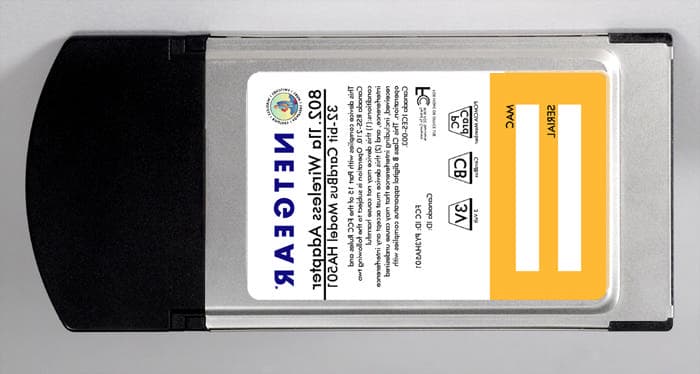
Click to zoom
Application Details
- Equipment Class
- NII - Unlicensed National Information Infrastructure TX
- Date of Grant
- Feb 05, 2002
- Application Purpose
- Original Equipment
- Date of Application
- Nov 15, 2001
- Frequency Range
- 5250.00000000 - 5350.00000000
- Company
- Netgear Incorporated
- Country
- United States
Documents & Files
Document Text
Text extracted from the exhibit documents filed with the FCC. Open a document above to read the original.
Users Manual
802.11a Wireless PC Card Model HA501 Quick Start Guide Rev 1.2.11 © 2001- 2002 by NETGEAR, Inc. All rights reserved. Trademarks NETGEAR is a registered trademark of NETGEAR, INC. Windows is a registered trademark of Microsoft Corporation. Other brand and product names are trademarks or registered trademarks of their respective holders. Information is subject to change without notice. All rights reserved. Statement of Conditions In the interest of improving internal design, operational function, and/or reliability, NETGEAR reserves the right to make changes to the products described in this document without notice. NETGEAR does not assume any liability that may occur due to the use or application of the product(s) or circuit layout(s) described herein. Federal Communications Commission (FCC) Compliance Notice: Radio Frequency Notice Netgear Inc., 4500 Great America Parkway, Santa Clara, CA 95054, (408) 907-8000, declares under our sole responsibility, that this device complies with part 15 of the FCC Rules. Operation is subject to the following two conditions: • This device may not cause harmful interference. • This device must accept any interference received, including interference that may cause undesired operation. Note: This equipment has been tested and found to comply with the limits for a Class B digital device, pursuant to part 15 of the FCC Rules. These limits are designed to provide reasonable protection against harmful interference in a residential installation. This equipment generates, uses, and can radiate radio frequency energy and, if not installed and used in accordance with the instructions, may cause harmful interference to radio communications. However, there is no guarantee that interference will not occur in a particular installation. If this equipment does cause harmful interference to radio or television reception, which can be determined by turning the equipment off and on, the user is encouraged to try to correct the interference by one or more of the following measures: • Reorient or relocate the receiving antenna, • Increase the separation between the equipment and receiver, • Connect the equipment into an outlet on a circuit different from that to which the receiver is connected, • Consult the dealer or an experienced radio/TV technician for help. Radio Frequency Interference Requirements This device is restricted to indoor use due to its operation in the 5.15 to 5.25 GHz frequency range. FCC requires this product to be used indoors for the frequency range 5.15 to 5.25 GHz to reduce the potential for harmful interference to co-channel Mobile Satellite systems. High power radars are allocated as primary users of the 5.25 to 5.35 GHz and 5.65 to 5.85 GHz bands. These radar stations can cause interference with and /or damage this device. Quick Start Guide This Quick Start Guide is intended for users familiar with PC Card and driver installation for Windows 98, Windows ME, and Windows 2000. Refer to "Installing the Documentation" on page four of this Quick Start Guide for information on setting up the online documentation. Installation for Windows 98, Windows Me, and Windows 2000 Before installing the driver, you will need a copy of the operating system installation media, usually a CD supplied with your computer or operating system. On Windows 98 systems, the installation files are sometimes archived on the hard disk in C:\WINDOWS\OPTIONS\CABS. On Windows 2000 systems, you may be prompted to load operating system files from the Windows 2000 installation disk. You will also need the End User Utilities CD supplied with your PC Card. The Setup program installs configuration utilities in the Network application in the Control Panel. Run Setup from the End User Utilities CD 1.. Turn on your computer. 2.. Put the End User Utilities CD in the CD-ROM drive. The setup program should start automatically. If it does not start, you can run it manually by selecting Run from the Start menu and running SETUP.EXE from the CDROM Drive. 3.. On the WLAN Menu screen, select Installation for Windows. 4.. Select Adapter Installation Instructions. Follow the instructions as they appear on the screen. 5.. When prompted, insert the PC Card into the PC Card slot (Figure 1). Align the card properly before putting it in the slot. Insert the card firmly without forcing until it seats snugly. X CAUTION: Forcing a misaligned card into the slot can damage the computer or the card. The driver-installation procedure guides you through the steps standard for your operating system. If you are unfamiliar with driver-installation procedures, refer to the Network Interface Card User Guide for details. You will be asked to supply CDs or directory-path information for the End User Utilities CD and your operation-system software. The setup program will install and open the Network application in the Control Panel as part of the driver-installation process. 6.. Enter the name of the Wireless LAN Service Area of the wireless network to which your computer will connect. The name you enter here must be identical to the name assigned to the access point. Capitalization, characters, and spacing must match exactly. X NOTE: If the access point you wish to associate with is set for encryption, you must also enable encryption on the wireless client. Click Advanced to go to screens where you can enable and configure encryption. You must set the wireless client for the same encryption algorithm and Shared Key values as the access point it will associate with. Refer to the Network Interface Card User Guide for more details about configuring encryption. 7.. Dave the configuration settings and exit by clicking OK. 8.. Restart your computer. 9.. Make sure that the network protocol parameters, including the IP address, gateway, and subnet mask, are set correctly for your computer. 10.. When the system reboots, restart the setup program and install any other required components. NETGEAR recommends that you install the wi…
Text truncated - open the document above for the full version.
Attestation Statements
Everybody’s connecting 4500 Great America Parkway Santa Clara, CA 95054 Phone: 408-907-8000 Fax: 408-907-8097 www.netgear.com Federal Communications Commission 7435 Oakland Mills Road Columbia, MD 21046 November 13, 2001 To Whom It May Concern: Atheros Communications has authorized NETGEAR to re-label and market these products using the NETGEAR model designations below. The relabeled products are identical in all respects to the original certified models apart from external labeling. This agreement applied to the specific models referenced below and remains in force indefinitely. Original Certified Models: Atheros AR5BCB-00013 Cardbus Adapter Relabeled Models: NETGEAR HA501 Cardbus PC Card FCC ID: PY3HA501 Sincerely, Mark Merrill Vice President of Engineering
Cover Letter(s)
File: R45301 November 12, 2001 Chief, Equipment Authorization Branch, Authorization and Evaluation Division, Office of Engineering and Technology FEDERAL COMMUNICATIONS COMMISSION P.O. Box 358315 Pittsburgh, PA 15251-5315 Gentlemen: The enclosed documents constitute a formal submittal and application for a Grant of Equipment Authorization pursuant to Subpart E of Part 15 of FCC Rules (CFR 47) regarding intentional radiators for the NetGear model HA501. Data within this report demonstrates that the equipment tested complies with the FCC limits for intentional radiators. Please note that the test report is based on testing performed on an Atheros Communications model AR5BCB-00013 Elliott Laboratories, as duly authorized agent prepared this submittal. A copy of the letter of our appointment as agent is enclosed. If there are any questions or if further information is needed, please contact Elliott Laboratories for assistance. Sincerely, Mark Briggs Director of Engineering MB/dmg
Cover Letter(s)
Everybody’s connecting 4500 Great America Parkway Santa Clara, CA 95054 Phone: 408-907-8000 Fax: 408-907-8097 www.netgear.com Federal Communications Commission 7435 Oakland Mills Road Columbia, MD 21046 November 12, 2001 Gentlemen: This is the letter of authorization to accept our appointment of Elliott Laboratories, Inc. as Agent for Netgear, Inc., 4500 Great America Parkway, Santa Clara, CA 95054, to sign applications before the Commission and to make representations to you on our behalf. Elliott Laboratories is to receive and exchange data between our company and the Commission. This authorization is made pursuant to Section 2.911(c) of the FCC Rules and expires on December 31, 2001. I hereby certify on behalf of Netgear, Inc., 4500 Great America Parkway, Santa Clara, CA 95054 (“Applicant”) that neither Applicant nor any party to the application (officers, directors, and 5% shareholders) is subject to a denial of Federal benefits that includes FCC benefits pursuant to section 5301 of the Anti-Drug Abuse Act of 1988. 21 U.S.C. 853a. Sincerely, Mark Merrill Vice President of Engineering
Cover Letter(s)
Everybody’s connecting 4500 Great America Parkway Santa Clara, CA 95054 Phone: 408-907-8000 Fax: 408-907-8097 www.netgear.com Federal Communications Commission Equipment Authorization Branch 7435 Oakland Mills Road Columbia, MD 21046 November 12, 2001 Dear Examiner: I am writing to avoid the possibility of an inadvertent disclosure of proprietary information. The accompanying Form 731 is being filed with the commission on our behalf by Elliott Laboratories, Inc., a consulting and testing laboratory. Included as exhibits with the enclosed application are block diagrams, schematics and a detailed description of the theory of operation of the device. It is our intention to provide the commission with a full disclosure of our product so that its merits can be evaluated. Indeed, we are pleased to provide any further information that the commission might wish to see. It is not our intention, however, to make our proprietary process a matter of public record. In view of the fact that the block diagrams, schematics, and associated theory of operation disclose the mechanism of our process, we ask that these portions (block diagrams, schematics, and theory of operation) of our application be withheld from public inspection as provided under FCC section 0.459. These documents contain details of the proprietary operation of the product. These details are not readily discernible – even to technically sophisticated individuals – from our hardware and constitute trade secrets. We request therefore that these documents and this letter be segregated from the body of our evaluation report and withhold from public inspection. Thank you for your attention. Please let the undersigned know if the Commission disagrees with our position or requires further justification. Sincerely, Mark Merrill Vice President of Engineering
External Photos
External Photographs
ID Label/Location Info
Label and Label Location The material and adhesive on the HA501 label are listed below: (1) HA501 front label Material: one-side coated with PP film. Adhesive: Acrylic (2) HA501 back label Material: one-side coated with PP film. Adhesive: Acrylic Label and Label Location
Internal Photos
Internal Photographs Internal Assembly View Top View of Board without shield Bottom View of Board
RF Exposure Info
SAR COMPLIANCE TESTING OF ATHEROS COMMUNICATIONS MODEL AR5BCB-00013 CARDBUS CARD INSERTED INTO A LAPTOP COMPUTER October 22, 2001 Submitted to:Mr. Eric Dukatz Senior RF Engineer Atheros Communications 529 Almanor Avenue Sunnyvale, CA 94085-3512 Submitted by:Om P. Gandhi Professor of Electrical and Computer Engineering University of Utah 50 S Central Campus Dr., Rm. 3280 Salt Lake City, UT 84112-9206 SAR COMPLIANCE TESTING OF ATHEROS COMMUNICATIONS MODEL AR5BCB-00013 CARDBUS CARD INSERTED INTO A LAPTOP COMPUTER I. Introduction The U.S. Federal Communications Commission (FCC) has adopted limits of human exposure to RF emissions from mobile and portable devices that are regulated by the FCC [1]. The FCC has also issued Supplement C (Edition 97-01) to OET Bulletin 65 [2] and a more recent version of the same [3] defining both the measurement and the computational procedures that should be followed for evaluating compliance of mobile and portable devices with FCC limits for human exposure to radiofrequency emissions. We have used the measurement procedure for SAR compliance testing of the Atheros Communications CardBus card (FCC ID: PPD-AR5BCB-00013) inserted into a laptop computer. A photograph of the unit with the CardBus card inserted into the laptop computer is given in Fig. 1. A picture of the Model AR5BCB-00013 CardBus card placed on the laptop is given in Fig. 2. The Atheros Model AR5BCB-00013 CardBus card operates with a transmit power to up to 21 dBm (126 mW). Since the wireless PC may possibly be placed on a user's lap where the RF antennas would be the closest to the body, a planar phantom model was used for SAR measurements. II. Experimental Measurements of SAR Distribution The testing of the SAR distribution for the Atheros Communications Model AR5BCB-00013 CardBus Card inserted into a laptop computer was done with a planar rectangular box phantom shown in Fig. 3. This box phantom of external dimensions 30 × 50 cm is filled with a tissue-simulant fluid up to a depth of 15.5 cm. To maintain flatness of the phantom, the rectangular box is made of acrylic (ε r = 2.56) of thickness 6.35 mm. The tissue-simulant fluid uses a composition developed at the University of Utah which 2 consists of 68.0% water, 31.0% sugar and 1% HEC. For this composition, we have measured the dielectric properties using a Hewlett Packard (HP) Model 85070B Dielectric Probe in conjunction with HP Model 8720C Network Analyzer (50 MHz-20 GHz). The measured dielectric properties at the mid band frequency of 5.30 GHz are as follows: ε r = 48.5 ± 1.7 and σ = 5.40 ± 0.08 S/m. From the FCC Supplement C [3], we obtain the desired dielectric properties to simulate the body tissue at 5.30 GHz to be ε r = 48.9 and σ = 5.42 S/m. Thus, the measured properties for the body-simulant fluid are close to the desired values. III. Calibration of the E-Field Probe As in some previously reported SAR measurements at 6 GHz [4], we have calibrated the Narda Model 8021 Miniature Broadband Electric Field Probe of tip diameter 4 mm (0.4 to 10 GHz) using a rectangular waveguide WR 159 that was filled with this body-simulant fluid at 5.30 GHz. By comparing the electric fields expected in the tissue from the analytical expressions of the waveguide theory, we obtain a calibration factor of 2.98 (mW/kg)/μV. This is considerably larger than calibration factors of 0.39 and 0.565 (mW/kg)/μV previously reported for the same probe at 835 MHz and 1900 MHz, respectively [5]. This is to be expected since the sensitivity of the diodes used for the Narda Model 8021 Miniature Broadband Electric Field Probe of tip diameter 4 mm is likely to diminish with frequency. I V . The Measured SAR Distributions The SAR distribution was determined using the automated SAR measurement system developed at the University of Utah [4]. As described in [4], this SAR measurement system has been validated using a number of wireless telephones at 835 and 1900 MHz, respectively. 3 The highest SAR region for each of the frequencies (5.26 and 5.32 GHz) was identified in the first instance by using a coarser sampling with a step size of 8.0 mm over three overlapping areas for a total scan area of 8.0 × 9.6 cm. After identifying the region of the highest SAR, the SAR distribution was measured with a resolution of 2 mm in order to obtain the peak 1 cm 3 or 1-g SAR. As given in [5], the SAR measurements are performed at 4, 6, 8, 10, 12 mm height from the bottom surface of the body-simulant fluid. The SARs thus measured were extrapolated to obtain values at 1, 3, 5, 7 and 9 mm height and used to obtain 1-g SARs. The estimated error in determination of peak 1-g SAR is within ± 20% as compared to the values obtained using numerical procedures [5]. The SAR distributions were measured for transmit frequencies of 5.26 and 5.32 GHz and are given in Tables 1 and 2. The peak 1-g SARs at 5.26 and 5.32 GHz are 0.402 and 0.331 W/kg, respectively. For the measurements in Tables 1 and 2, the separation between the Atheros Model AR5BCB-00013 CardBus card and the bottom of the experimental phantom is on the order of 1 cm and yet the peak 1-g SAR is only 0.331- 0.402 W/kg. The end-on SAR value (for a bystander), where the spacing is larger and may be on the order of 2.5 cm or more, is likely to be smaller and was, therefore, not measured. V. Comparison of the Data With FCC 96-326 Guidelines According to the FCC 96-326 Guidelines [1], the peak SAR for any 1-g of tissue should not exceed 1.6 W/kg. For the maximum radiated power condition of 21 dBm (126 mW), the Atheros Communications Model AR5BCB-00013 CardBus card has been measured to give peak 1-g SARs of 0.331-0.402 W/kg which are considerably smaller than 1.6 W/kg. 4 REFERENCES 1 .Federal Communications Commission, "Guidelines for Evaluating the Environmental Effects of Radiofrequency Radiation," FCC 96-326, August 1, 1996. 2 .K. Chan, R. F. Cleveland, Jr., and D. L. Means, "Evaluating Compliance With FCC Guidelines for Human Exposure to Radiofre…
Text truncated - open the document above for the full version.
RF Exposure Info
RF Exposure Information - Addendum Re: FCC ID PY3HA501 Applicant: NetGear Incorporated The application for the above device included a SAR report. This SAR report details results for a phantom-to-EUT separation of 1cm. While the profile of most laptops will ensure this separation distance, under certain circumstances it may be possible that the end user could come closer than 1cm to the device. For this reason, the following warning statement will be placed in a prominent location in the User's Manual: Warning To comply with the FCC's rf exposure requirements you must maintain a distance of at least 1cm from the antenna of this device while it is in use. This device should not be co-located with other transmitters.
RF Exposure Info
January 11, 2002 RESPONSES TO FCC QUESTIONS ON THE SAR COMPLIANCE TEST REPORT OF ATHEROS MODEL AR5BCB-00013 DATED NOVEMBER 20, 2001 1.Please use Suppl. C ed 01-01 for all future filings. Due to differing tabulated frequencies, it is unknown whether or not liquid parameters in EA728513 comply with Suppl.. C 01-01. Response: FCC Suppl. C ed 01-01 has indeed been used in preparing this SAR report as far as possible. Though not specifically written at the end of Section II, the desired dielectric properties ε r = 48.9 and σ = 5.42 S/m for "body" tissue at 5.3 GHz were obtained by interpolating the dielectric properties at 3.0 and 5.8 GHz given in Appendix C of FCC Suppl. C ed 01-01. This is a valid procedure since Ref. 12 of FCC Suppl. C ed 01-01 does not give properties for the so-called "body" tissue and Ref. 11 gives properties for the head model only up to 3.0 GHz. 2 .Measurement uncertainty budget is needed. Response: We intend to submit a detailed analysis of the measurement uncertainty budget in future filings. Our present estimate of the measurement accuracy of ±20% is based on the peak 1-g SARs measured as well as calculated for dipole antennas placed against planar phantoms and a number of actual telephones placed against the phantom model of the head [see Ref. 5 of the SAR report -- Q. Yu, et al., IEEE Trans. EMC, Vol. 41(3), pp. 234- 245, August 1999]. Also, a measured peak 1-g SAR of 0.134 W/kg as against an FDTD- calculated SAR of 0.129 W/kg was previously reported for the SAR report of EA101903 which is a very similar device at 5.25 GHz radiating only 16 dBm conducted power. This difference of less than 4% is certainly within the ±20% uncertainty in measured SARs reported for the present SAR compliance test report. 3 .Only 1, 3, 5, 7, 9 mm layer values are shown. Are these interpolated from 4, 6, 8, 10, 12 measured values? Were 4, 6, 8, 10, 12 measured values used in averaging? Response: The SAR values are extrapolated from the values measured at depths of 4, 6, 8, 10 and 12 mm by using a polynomial fit to the data for various locations. To determine peak 1-cm 3 SAR, the extrapolated data thus obtained for depths of 1, 3, 5, 7 and 9 mm is used. 4 .What is loss tangent of 6.35 mm-thick flat phantom at 5.3 GHz? Response: The dielectric constant of the acrylic polystyrene is ε r = 2.56 and its loss tangent given in ITT Handbook [a] is 0.00033 at 3 GHz and 0.0012 at 25 GHz. Thus, the loss tangent is considerably lower than 0.05 suggested as the upper limit in FCC Suppl. C ed 01-01. 2 5 .To verify liquid depth and proper test system operation, we have been requesting graphs of SAR vs. depth into liquid at the peak SAR configuration(s). In future filings, please provide such graphs. Response: The measured variations of SAR vs. depth into the liquid at the peak SAR locations from Tables 1 and 2 of the SAR report are plotted in Fig. a while those from Tables 3 and 4 of the SAR report are plotted in Fig. b. Both Figs. a and b are attached here. 6 .Figures 1, 2 appear to be identical to Figs. 1, 2 in the SAR report of EA101903. Are these identical devices? Response: Figures 1 and 2 are indeed similar to Figs. 1 and 2 in the SAR report of EA101903 since the devices are similar in external appearance and a similar PC is used. [a]ITT Handbook, Reference Data for Radio Engineers, Fifth Edition, Howard W. Sams & Co. Inc., p. 4-29, 1968. 3 012345678910 0 0.1 0.2 0.3 0.4 0.5 0.6 0.7 0.8 0.9 1 Depth into Liquid (mm) SAR (W/kg) 5.26 GHz 5.32 GHz Fig. a.Plot of the SAR variations as a function of depth in the liquid for locations of peak SAR from Tables 1 and 2 (Above-lap position) of the SAR Compliance Test Report. 4 012345678910 0 0.2 0.4 0.6 0.8 1 1.2 1.4 1.6 1.8 2 Depth into Liquid (mm) SAR (W/kg) 5.26 GHz 5.32 GHz Fig. b. Plot of the SAR variations as a function of depth in the liquid for locations of peak SAR from Tables 3 and 4 (End-on position) of the SAR Compliance Test Report.
Test Report
File: R45301 Page 1 of 18 Electromagnetic Emissions Test Report and Application for Grant of Equipment Authorization pursuant to FCC Part 15, Subpart E (UNII Devices) and Industry Canada RSS 210 Issue 4 (LELAN Devices) on the Netgear Model: HA501 FCC ID: PY3HA501 GRANTEE: Netgear 4401 Great America Parkway Santa Clara, CA. 95052-8185 TEST SITE: Elliott Laboratories, Inc. 684 W. Maude Avenue Sunnyvale, CA 94086 REPORT DATE: November 12, 2001 FINAL TEST DATE: October 18, 2001 AUTHORIZED SIGNATORY: ______________________________ Mark Briggs Director of Engineering This report shall not be reproduced, except in its entirety, without the written approval of Elliott Laboratories, Inc. Elliott Laboratories, Inc. -- EMC Department Test Report Report Date: November 12, 2001 File: R45301 Page 2 of 18 Pages DECLARATIONS OF COMPLIANCE Equipment Name and Model: HA501 Manufacturer: Netgear 4401 Great America Parkway Santa Clara, CA. 95052-8185 Tested to applicable standards: RSS-210, Issue 4, December 2000 (Low Power License-Exempt Radiocommunication Devices) FCC Part 15 Subpart E (UNII Devices) Measurement Facility Description Filed With Department of Industry: Departmental Acknowledgement Number: IC2845 SV2 Dated August 8, 2001 Departmental Acknowledgement Number: IC2845 SV4 Dated August 20, 2001 I declare that the testing was performed or supervised by me; that the test measurements were made in accordance with the above mentioned departmental standards (through the use of ANSI C63.4 as detailed in section 5.3 of RSS-210, Issue 4); and that the equipment performed in accordance with the data submitted in this report. Signature ______________________________ Name Mark Briggs Title Director of Engineering Company Elliott Laboratories Inc. Address 684 W. Maude Ave Sunnyvale, CA 94086 USA Date: November 12, 2001 Maintenance of compliance with the above standards is the responsibility of the manufacturer. Any modification of the product which may result in increased emissions should be checked to ensure compliance has been maintained (i.e., printed circuit board layout changes, different line filter, different power supply, harnessing or I/O cable changes, etc.). Elliott Laboratories, Inc. -- EMC Department Test Report Report Date: November 12, 2001 File: R45301 Page 3 of 18 Pages TABLE OF CONTENTS COVER PAGE............................................................................................................................1 DECLARATIONS OF COMPLIANCE......................................................................................................................................2 TABLE OF CONTENTS...............................................................................................................................................................3 SCOPE.............................................................................................................................................................................................4 OBJECTIVE...................................................................................................................................................................................4 SUMMARY OF RESULTS...........................................................................................................................................................5 MEASUREMENT UNCERTAINTIES....................................................................................................................................6 EQUIPMENT UNDER TEST (EUT) DETAILS..........................................................................................................................7 GENERAL...................................................................................................................................................................................7 ENCLOSURE..............................................................................................................................................................................7 MODIFICATIONS....................................................................................................................................................................7 SUPPORT EQUIPMENT..........................................................................................................................................................7 EUT INTERFACE PORTS........................................................................................................................................................8 EUT OPERATION.....................................................................................................................................................................8 ANTENNA REQUIREMENTS................................................................................................................................................8 TEST SITE......................................................................................................................................................................................9 GENERAL INFORMATION....................................................................................................................................................9 CONDUCTED EMISSIONS CONSIDERATIONS................................................................................................................9 RADIATED EMISSIONS CONSIDERATIONS....................................................................................................................9 MEASUREMENT INSTRUMENTATION................................................................................................................................10 RECEIVER SYSTEM...............................................................................................................................................................10 INSTRUMENT CONTROL COMPUTER.......................................................…
Text truncated - open the document above for the full version.
Test Report
Table comparing previous and new measurements of peak power for CB11 Original Test Data as submitted to the FCC: Mode: Frequency:518052605320521052505290 Original average power (in Elliott FCC submission, as measured with a power meter and thermal sensor) 13.817.616.313.813.917.5 -26dB emission BW (in MHz)283836524572 Original peak power as reported to FCC (in Elliott FCC submission, measurement made using the analyzer's internal channel power measurement function with the RBW=1MHz and VBW=30kHz and integration bandwidth set to 50MHz) 14.819.117.815.215.419.1 New Test Data, taken 1/8/2002: Mode: Frequency:518052605320521052505290 Average power (dBm) (to ensure output power the same levels that were used when making the FCC application): 13.717.516.613.713.817.6 Channel integration BW (MHz) used to calculate peak power 383838727272 New peak power (dBm) (Measured with Agilent E4404B channel power measurement function with RBW=1MHz and VBW > emission bandwidth divided by 2 * pi * 30). Refer to plots to verify instrument settings. 16.1dBm (VBW=300k Hz) 20.2dBm (VBW=300k Hz) 19.1dBm (VBW=300k Hz) 15.7dBm (VBW=300k Hz) 16.4dBm (VBW = 300kHz) 22.4 dBm (VBW = 1MHz) FCC limit (dBm)172424171724 base (802.11a or "Normal")turbo base (802.11a or "Normal")turbo Notes on analyzer screen shots: As requested (and can be seen in the screen shots) RBW=1MHz, VBW=300kHz, Peak detector The analyzer's channel power measurement capability is used as suggested by FCC For convenience, the widest -26dB BW is used as the channel integration BW for all cases in each mode The analyzer screen values do not account for 1.3dB of cable loss. This 1.3dB has been included in the table of test results. Test equipment used: Agilent E4404B SN#US39240259, calibrated on 10/12/01, due for calibration 10/12/02.
Test Setup Photos
Test Configuration Photographs Radiated Emissions, 30 – 1000 MHz Test Configuration Photographs Radiated Emissions1000 - 40000 MHz Test Configuration Photographs Test Configuration Photographs
Contact Information
Applicant
David Kay
Technical Contact
ELLIOTT LABORATORIESMARK R BRIGGS
[email protected]408-245-7800
684 WEST MAUDE AVE · SUNNYVALE, California · United States
Non-Technical Contact
ELLIOTT LABORATORIESJENNIFER L SANCHEZ
[email protected]4082457800
Test Firm
Elliott Laboratories LLCDavid Bare
Technical Specifications
| # | Rule Parts | Frequency Range | Power Output | Tolerance |
|---|---|---|---|---|
| 2 | 15E | 5.25 GHz - 5.35 GHz | 174.00 mW | ppm |
Other Applications from Netgear Incorporated

PY325100647
Aug 04, 2026BE5000 Dual-Band PoE 2.5G Insight Managed WiFi 7 Outdoor Access Point
Equipment Class
DTS - Digital Transmission SystemPY325300652
May 12, 2026BE5000 Dual-Band PoE 2.5G Insight Managed WiFi 7 Access Point
Equipment Class
NII - Unlicensed National Information Infrastructure TXPY325400656
Apr 16, 2026Orbi Outdoor Satellite
Equipment Class
DTS - Digital Transmission SystemPY324400640
Dec 12, 2025Orbi 11BE WiFi 7 Tri-band Router, Orbi 11BE WiFi 7 Tri-band Satellite
Equipment Class
NII - Unlicensed National Information Infrastructure TXPY324100618
Jul 31, 2024Nighthawk 5G Mobile Router
Equipment Class
PCB - PCS Licensed Transmitter