PY3HE102Wireless Access Point Module
Netgear Incorporated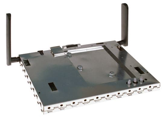
Click to zoom
Application Details
- Equipment Class
- NII - Unlicensed National Information Infrastructure TX
- Date of Grant
- Dec 17, 2001
- Application Purpose
- Original Equipment
- Date of Application
- Dec 17, 2001
- Equipment Note
- Wireless Access Point Module
- Frequency Range
- 5250.00000000 - 5350.00000000
- Company
- Netgear Incorporated
- Country
- United States
Documents & Files
Document Text
Text extracted from the exhibit documents filed with the FCC. Open a document above to read the original.
Users Manual
Preliminary Access Point User’s Guide • Page 1 802.11a Wireless Access Point Model HE102 User’s Guide Rev 1.2.11 Preliminary Page 2 • Access point User’s Guide © 2001- 2002 by NETGEAR, Inc. All rights reserved. Trademarks NETGEAR is a registered trademark of NETGEAR, INC. Windows is a registered trademark of Microsoft Corporation. Other brand and product names are trademarks or registered trademarks of their respective holders. Information is subject to change without notice. All rights reserved. Statement of Conditions In the interest of improving internal design, operational function, and/or reliability, NETGEAR reserves the right to make changes to the products described in this document without notice. NETGEAR does not assume any liability that may occur due to the use or application of the product(s) or circuit layout(s) described herein. FCC REGULATORY STATEMENT This equipment has been tested and found to comply with the limits for a Class B digital device, pursuant to Part 15 of the FCC Rules. These limits are designed to provide reasonable protection against harmful interference in a residential installation. This equipment generates, uses, and can radiate radio frequency energy and, if not installed and used in accordance with the instructions, may cause harmful interference to radio communications. However, there is no guarantee that interference will not occur in a particular installation. If this equipment does cause harmful interference to radio or television reception, with can be determined by turning the equipment of and on, the user is encouraged to try to correct the interference by on or more of the following measures: • Reorient or relocate the receiving antenna. • Increase the separation between the equipment and the receiver. • Connect the equipment into an outlet on a circuit different from that which the receiver is connected. • Consult the dealer or an experienced radio/TXV technician for help. Modifications made to the product, unless expressly approved by NETGEAR, INC., could void the user’s authority to operate the equipment. RF Exposure Requirements WARNING!! To ensure compliance with FCC RF exposure requirements, the antenna used for this device must be installed to provide a separation distance of at least 20 cm from all persons and must not be co-located or operating in conjunction with any other antenna or radio transmitter. Installers and end-users must follow the installation instructions provided in this user guide. Radio Frequency Interference Requirements This device is restricted to indoor use due to its operation in the 5.15 to 5.25 GHz frequency range. FCC requires this product to be used indoors for the frequency range 5.15 to 5.25 GHz to reduce the potential for harmful interference to co-channel Mobile Satellite systems. High power radars are allocated as primary users of the 5.25 to 5.35 GHz and 5.65 to 5.85 GHz bands. These radar stations can cause interference with and /or damage this device. Preliminary Access Point User’s Guide • Page 3 Table of Contents 1 INTRODUCTION.....................................................................................................4 1.1 SCOPE..................................................................................................................4 1.2 FEATURES............................................................................................................4 2 GETTING TO KNOW THE MODEL HE102 ACCESS POINT........................5 2.1 FRONT VIEW........................................................................................................5 2.2 REAR VIEW..........................................................................................................6 3 AP NETWORK ATTACHMENT AND CONFIGURATION.............................8 3.1 AP NETWORK CONFIGURATION AND NETWORK BOOT........................................8 3.2 CONFIGURING THE AP THROUGH WEB BROWSER..............................................11 APPENDIX A—AP WEB SERVER.............................................................................16 INTRODUCTION..............................................................................................................16 ACCESSING THE AP WEB SERVER.................................................................................16 SETUP............................................................................................................................18 WEP..............................................................................................................................20 Preliminary Page 4 • Access point User’s Guide 1 Introduction 1.1 Scope The intent of this document is to familiarize you with the NETGEAR Model HE102 Access Point (AP), its physical characteristics, setup, configuration, and usage. 1.2 Features The Model HE102 Access Point is an IEEE 802.11a AP supporting up to 60 IEEE 802.11a station associations including the AP itself. Rates of 6 to 54 Mbps are supported in standard IEEE 802.11a mode, and 12 to 72 Mbps in turbo mode. All transmission rates are supported across the lower and middle bands of the 5 GHz spectrum(5.15 to 5.35 GHz). Preliminary Access Point User’s Guide • Page 5 2 Getting to Know the Model HE102 Access Point 2.1 Front View The Model HE102 Access Point (AP) has 3 LED’s, and a pair of side-mounted antennas that rotate 180° for alternative reception positioning and compact packaging. Table 1 – LED Functionality LED 1 Description Off No Power On Power On and Ready for Operation Blink Power On but Not Ready for Operation – at initial power on or reset, this indicates self-test or software loading; at other times, this indicates a system fault LED 1 (Power Status) LED 2 (Ethernet Link) LED 3 (Wireless Link) Preliminary Page 6 • Access point User’s Guide LED 2 Description Off No Ethernet Link Detected Green On 100 Mbps Link Detected but No Activity Green Blink 100 Mbps Link Activity – blink rate is proportional to activity Amber O…
Text truncated - open the document above for the full version.
Cover Letter(s)
Everybody’s connecting 4500 Great America Parkway Santa Clara, CA 95054 Phone: 408-907-8000 Fax: 408-907-8097 www.netgear.com American TCB 6731 Whittier Ave Suite C110 McLean, VA. 22101 November 12, 2001 Gentlemen: This is the letter of authorization to accept our appointment of Elliott Laboratories, Inc. as Agent for Netgear, Inc., 4500 Great America Parkway, Santa Clara, CA 95054, to sign applications before the Commission and to make representations to you on our behalf. Elliott Laboratories is to receive and exchange data between our company and the Commission. This authorization is made pursuant to Section 2.911(c) of the FCC Rules and expires on December 31, 2001. I hereby certify on behalf of Netgear, Inc., 4500 Great America Parkway, Santa Clara, CA 95054 (“Applicant”) that neither Applicant nor any party to the application (officers, directors, and 5% shareholders) is subject to a denial of Federal benefits that includes FCC benefits pursuant to section 5301 of the Anti-Drug Abuse Act of 1988. 21 U.S.C. 853a. Sincerely, Mark Merrill Vice President of Engineering
Cover Letter(s)
Everybody’s connecting 4500 Great America Parkway Santa Clara, CA 95054 Phone: 408-907-8000 Fax: 408-907-8097 www.netgear.com American TCB 6731 Whittier Ave Suite C110 McLean, Va. 22101 November 12, 2001 Dear Examiner: I am writing to avoid the possibility of an inadvertent disclosure of proprietary information. The accompanying Form 731 is being filed with the commission on our behalf by Elliott Laboratories, Inc., a consulting and testing laboratory. Included as exhibits with the enclosed application are block diagrams, schematics, and a detailed description of the theory of operation of the device. It is our intention to provide the commission with a full disclosure of our product so that its merits can be evaluated. Indeed, we are pleased to provide any further information that the commission might wish to see. It is not our intention, however, to make our proprietary process a matter of public record. In view of the fact that the block diagrams, schematics, and associated theory of operation disclose the mechanism of our process, we ask that these portions (block diagrams, schematics, and theory of operation) of our application be withheld from public inspection as provided under FCC section 0.459. These documents contain details of the proprietary operation of the product. These details are not readily discernible – even to technically sophisticated individuals – from our hardware and constitute trade secrets. We request therefore that these documents and this letter be segregated from the body of our evaluation report and withhold from public inspection. Thank you for your attention. Please let the undersigned know if the Commission disagrees with our position or requires further justification. Sincerely, Mark Merrill Vice President of Engineering
Cover Letter(s)
Ref: NetGear, Inc (FCC ID: PY3HE102) Dear Bill, In response to the comments made on November 28, 2001 regarding NetGear, Inc (FCC ID: PY3HE102), please see my responses below: 1.) Please note label must appear on module. Correct and submit new label location information. This has been done. The new file is named label and location - Revised.pdf 2.) A letter itemizing all the various parameters satisfied for this module approval was not submitted. Please correct. The page from the report has been extracted and uploaded as a separate document 3.) The antenna listed in the RF Exposure section identifies this as a 6dBi monopole. This seems a bit high. Could you please confirm from manufacturer, or measure antenna gain. The antenna manufacturer confirms that the gain of the antenna is 6dBi, despite its appearance ! Please also note that the name of the device is now “802.11a Wireless AP module”. As this does not affect any of the information in the Form 731 I am not sending you a revised for 731. The FRN for Netgear is 0005-0491-68 Hopefully the above answers all of your concerns. If not, please respond to [email protected] with any further questions. Regards, Mark Briggs Director of Engineering
Cover Letter(s)
American Telecommunications Certification Body Inc. 6731 Whittier Ave, McLean, VA 22101 November 28, 2001 RE: Netgear, Inc FCC ID: PY3HE102 I have a couple of notes on this Application. 1.) Please note label must appear on module. Correct and submit new label location information. 2.) A letter itemizing all the various parameters satisfied for this module approval was not submitted. Please correct. 3.) The antenna listed in the RF Exposure section identifies this as a 6dBi monopole. This seems a bit high. Could you please confirm from manufacturer, or measure antenna gain. Thanks, William H. Graff President and Examining Engineer mailto: [email protected] The items indicated above must be submitted before processing can continue on the above referenced application. Failure to provide the requested information may result in application termination. Correspondence should be considered part of the permanent submission and may be viewed from the Internet after a Grant of Equipment Authorization is issued. Please do not respond to this correspondence using the email reply button. In order for your response to be processed expeditiously, you must submit your documents through the AmericanTCB.com website. Also, please note that partial responses increase processing time and should not be submitted. Any questions about the content of this correspondence should be directed to the sender.
Cover Letter(s)
Elliott Laboratories, Inc. -- EMC Department Test Report Report Date: November 12, 2001 R45305 (FCC ID PY3HE102) Modular Justification Letter MODULAR APPROVAL REQUIREMENTS Modular approval for the device is being requested. The device must meet the eight requirements outlined in FCC Public Notice DA 00-1407 Released: June 26, 2000. Each requirement is addressed below: 1) The modular transmitter must have its own RF shielding. The EUT contains its own rf shielding. It was tested without an enclosure 2) The modular transmitter must have buffered modulation/data inputs. The data input is provided by a 10/100Mb/s ethernet interface. The data is buffered and data rate limited by the ethernet interface circuitry. 3) The modular transmitter must have its own power supply regulation. The EUT contains a separate dc power input connector. The dc power is fully regulated before it goes to any of the rf or digital circuits. 4) The modular transmitter must comply with the antenna requirements of Section 15.203 and 15.204(c). The antenna is integral to the device and so meets all requirements of 15.203 and of FCC Part 15 Subpart E. 5) The modular transmitter must be tested in a stand-alone configuration. The EUT was tested in a stand-alone configuration with cables connected to the ethernet and dc power ports representative of those that would be connected during normal use. 6) The modular transmitter must be labeled with its own FCC ID number, and, if the FCC ID is not visible when the module is installed inside another device, then the outside of the device into which the module is installed must also display a label referring to the enclosed module. The device is intended to be used by NetGear in their AccessPoint products. The devices containing the module will be labeled with the FCC ID of the module. 7) The modular transmitter must comply with any specific rule or operating requirements applicable to the transmitter and the manufacturer must provide adequate instructions along with the module to explain any such requirements. A copy of these instructions must be included in the application for equipment authorization. The device is intended to be used by the module manufacturer, NetGear, in their AccessPoint products. The operating limitations are fully understood by their engineering division. 8) The modular transmitter must comply with any applicable RF exposure requirements. The MPE calculations show that the device meets the rf exposure requirements provided that a separation of at least 20cm is maintained between the EUT and people in its vicinity. The installation and user manuals for products containing this module will all reference this requirement.
External Photos
External Photographs Top and Bottom Views
ID Label/Location Info
Label and Location Revised for Modular Approval The label (or similar) on the following page will be placed on the outside enclosure of the device containing the module 69.3 X 49.3 mm69.3 X 49.3 mm (A) Model HE102 802.11a Wireless Access Point This device complies with Part 15 of the FCC Rules and Canada RSS-210. Operation is subject to the following two conditions:(1) this device may not cause harmful interference, and (2) this device must accept any interference received, including interference that may cause undesired operation. This Class B digital apparatus complies with Canada ICES-003. Contains Tx FCC ID: PY3HE102 Canada ID: 4054104650A The next two pages show the label that will be placed on the module itself and its location on the outside surface of the module’s shield. 40 X 32 mm 802.11a Wireless AP module R FCC ID: PY3HE102 This device complies with Part 15 of the FCC Rules and Canada RSS-210. Operation is subject to the following two conditions:(1) this device may not cause harmful interference, and (2) this device must accept any interference received, including interference that may cause undesired operation. This Class B digital apparatus complies with Canada ICES-003.
Internal Photos
Internal Photographs Top Shield Removed Assembly View showing top shield Circuit board top view Circuit board bottom view
RF Exposure Info
MPE Calculations FCC part 1.1310, Table 1 limits the power density for uncontrolled exposure to 1mW/ cm 2 for systems operating in the UNII bands. The distance, d(cm) from the antenna at which the power density, P d (mW/cm 2 ) is below this limit is calculated from the maximum EIRP, P t (mW) using the equation: P d = P t /(4 pd 2 ) Re-arranging for the distance at which the power density is 1mW/cm2 gives: d = √ (P t /(4 p)) The device under test is designed to use an integral antenna with a gain of 6dBi. The maximum output power across all channels is 19.8dBm, giving an EIRP of 25.8 dBm (380 mW): d = √ (380/(4 p)) = 5.5 cm (2.2”) The distance from the antenna that the power density is 1mW/ cm 2 is, therefore, 5.5cm. The users guide instructs the user *(in two separate sections) to install the device such that it has a separation of at least 20cm from persons (see text below) to comply with the FCC’s requirements. This separation of 20cm more than meets the FCC’s and Industry Canada rf exposure requirements. Installation Note: To ensure compliance with FCC RF exposure requirements, the antenna used for this device must be installed to provide a separation distance of at least 20 cm from all persons. RF Exposure Requirements To ensure compliance with FCC RF exposure requirements, the antenna used for this device must be installed to provide a separation distance of at least 20 cm from all persons and must not be co- located or operating in conjunction with any other antenna or radio transmitter. Installers and end- users must follow the installation instructions provided in this user guide.
Test Report
R45305 Page 1 of 18 Electromagnetic Emissions Test Report and Application for Grant of Equipment Authorization pursuant to FCC Part 15, Subpart E (UNII Devices) on the Netgear Model: HE102 FCC ID: PY3HE102 GRANTEE: Netgear 4401 Great America Parkway Santa Clara, Ca. 95052 TEST SITE: Elliott Laboratories, Inc. 684 W. Maude Avenue Sunnyvale, CA 94086 REPORT DATE: November 12, 2001 FINAL TEST DATE: November 2 and November 6, 2001 AUTHORIZED SIGNATORY: ______________________________ Mark Briggs Director of Engineering This report shall not be reproduced, except in its entirety, without the written approval of Elliott Laboratories, Inc. Elliott Laboratories, Inc. -- EMC Department Test Report Report Date: November 12, 2001 R45305 Page 2 of 18 Pages DECLARATIONS OF COMPLIANCE Equipment Name and Model: HE102 Manufacturer: Netgear Tested to applicable standards: FCC Part 15 Subpart E (UNII Devices) I declare that the testing was performed or supervised by me; that the test measurements were made in accordance with the above-mentioned departmental standards and that the equipment performed in accordance with the data submitted in this report. Signature ______________________________ Name Mark Briggs Title Director of Engineering Company Elliott Laboratories Inc. Address 684 W. Maude Ave Sunnyvale, CA 94086 USA Date: November 12, 2001 Maintenance of compliance with the above standards is the responsibility of the manufacturer. Any modification of the product, which may result in increased emissions, should be checked to ensure compliance has been maintained (i.e., printed circuit board layout changes, different line filter, different power supply, harnessing or I/O cable changes, etc.). Elliott Laboratories, Inc. -- EMC Department Test Report Report Date: November 12, 2001 R45305 Page 3 of 18 Pages TABLE OF CONTENTS COVER PAGE...................................................................................................................................................................................1 DECLARATIONS OF COMPLIANCE......................................................................................................................................2 TABLE OF CONTENTS..............................................................................................................................................................3 SCOPE............................................................................................................................................................................................4 OBJECTIVE...................................................................................................................................................................................4 SUMMARY OF RESULTS...........................................................................................................................................................5 MEASUREMENT UNCERTAINTIES......................................................................................................................................6 MODULAR APPROVAL REQUIREMENTS...........................................................................................................................7 EQUIPMENT UNDER TEST (EUT) DETAILS..........................................................................................................................8 GENERAL...................................................................................................................................................................................8 ANTENNA..................................................................................................................................................................................8 ENCLOSURE...............................................................................................................................................................................8 MODIFICATIONS.....................................................................................................................................................................8 SUPPORT EQUIPMENT...........................................................................................................................................................9 EUT INTERFACE PORTS.........................................................................................................................................................9 EUT OPERATION......................................................................................................................................................................9 ANTENNA REQUIREMENTS..................................................................................................................................................9 TEST SITE....................................................................................................................................................................................10 GENERAL INFORMATION...................................................................................................................................................10 CONDUCTED EMISSIONS CONSIDERATIONS.................................................................................................................10 RADIATED EMISSIONS CONSIDERATIONS.....................................................................................................................10 MEASUREMENT INSTRUMENTATION................................................................................................................................11 RECEIVER SYSTEM................................................................................................................................................................11 INSTRUMENT CONTROL COMPUTER.............................................................................................................................11 LINE I…
Text truncated - open the document above for the full version.
Test Setup Photos
Test Configuration Photographs Radiated Emissions Test Configuration Conducted Emissions Test Configuration
Contact Information
Applicant
David Kay
Technical Contact
Elliott Laboratories, Inc.Juan Martinez
[email protected]408 245 7800
684 W. Maude Avenue · Sunnyvale, California · United States
Test Firm
Elliott Laboratories LLCDavid Bare
Technical Specifications
| # | Rule Parts | Frequency Range | Power Output |
|---|---|---|---|
| 2 | 15E | 5.25 GHz - 5.35 GHz | 91.00 mW |
Other Applications from Netgear Incorporated

PY325100647
Aug 04, 2026BE5000 Dual-Band PoE 2.5G Insight Managed WiFi 7 Outdoor Access Point
Equipment Class
DTS - Digital Transmission SystemPY325300652
May 12, 2026BE5000 Dual-Band PoE 2.5G Insight Managed WiFi 7 Access Point
Equipment Class
NII - Unlicensed National Information Infrastructure TXPY325400656
Apr 16, 2026Orbi Outdoor Satellite
Equipment Class
DTS - Digital Transmission SystemPY324400640
Dec 12, 2025Orbi 11BE WiFi 7 Tri-band Router, Orbi 11BE WiFi 7 Tri-band Satellite
Equipment Class
NII - Unlicensed National Information Infrastructure TXPY324100618
Jul 31, 2024Nighthawk 5G Mobile Router
Equipment Class
PCB - PCS Licensed Transmitter