PY3MA521802.11b Wireless PC Card 32-bit CardBus
Netgear Incorporated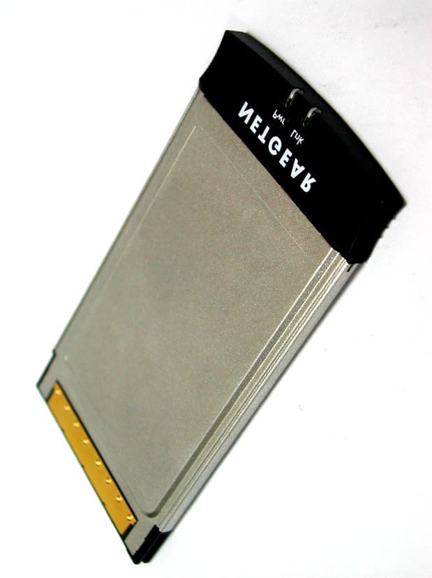
Click to zoom
Application Details
- Equipment Class
- DTS - Digital Transmission System
- Date of Grant
- Apr 16, 2003
- Application Purpose
- Original Equipment
- Date of Application
- Apr 16, 2003
- Equipment Note
- 802.11b Wireless PC Card 32-bit CardBus
- Frequency Range
- 2412.00000000 - 2462.00000000
- Company
- Netgear Incorporated
- Country
- United States
Documents & Files
Document Text
Text extracted from the exhibit documents filed with the FCC. Open a document above to read the original.
Users Manual
c. Follow the on-screen instructions to install the driver for the MA521 802.11b Wireless PC Card. • For Windows 98/Me users, once the [Please insert the disk labeled “Windows 98/Me CD-ROM,” and then click OK] window appears, enter the path corresponding to the appropriate drives and click OK. Usually these files can be found at C:\Windows or C:\Windows\System. • For Windows 2000 users, a Digital Signature Not Found message may appear. Click Ye sto proceed. • For Windows XP users, a Windows Logo Testing Not Found dialog box may appear. Click Continue Anywayto proceed. d. Click Finishto complete the installation. 3 3 Verify the Driver Installation a. From the Windows desktop, right-click My Computer. b. Click Properties. c. Open Device Manager: • Windows 98/Me users– Select the Device Manager folder tab. • Windows 2000/XP users– Select the Hardwarefolder tab, and click on the Device Managerbutton. d. Double-click Network Adapters. There should be no yellow exclamation mark or red cross icon on the NETGEAR MA521 802.11b Wireless PC Card selection, as shown here. Installation Guide Follow these quick steps to install your PC Card. Important Note:You must first install the software before you plug the card into your computer. Estimated Setup time: 10-15 minutes. 1 1 Install the MA521 Driver and Utility Software a. Turn on your computer. b. Insert the GearBox ™ CD for Wireless PC Card into the CD-ROM drive. c. The Autostart Wizard screen will appear, as shown here: d. Click the Install Driver & Utilityoption. e. If the Autorun wizard does not automatically start, go to your Windows Start menu and choose Run, and type D:/Setup.exe (“D” represents your CD-ROM drive letter), and click OK. f. The InstallShield Wizard screen will appear. Click Nextto continue. g. The Choose Destination Location screen will display the default Destination Folder. If you want to change the default folder, click Browseand choose a different destination folder. Then, click Nextto continue to the next screen. h. Modify the Program Folders field, if desired. Click Nextto continue. InstallShield will start copying files onto your system. i. Click Finishto complete installing the Configuration Utility. 2 2 Install the MA521 Wireless PC Card a. Insert the MA521 802.11b Wireless PC Cardinto available CardBus slot on your computer as shown here. b. Windows will automatically detect the MA521 802.11b Wireless PC Card and the Found New Hardware Wizard dialog box will appear. MA521 802.11b Wireless PC Card W ire le ss PC C a rd 32-bit CardBus WG5113 2 - b i t C a r d B u s W G 5 1 1 Notebook PC with MA521 802.11b Wireless PC Card Technical Support PLEASE REFER TO THE SUPPORT INFORMATION CARD THAT SHIPPED WITH YOUR PRODUCT. By registering your product at www.NETGEAR.com/register,we can provide you with faster expert technical support and timely notices of product and software upgrades. NETGEAR, INC. Support Information Phone: 1-888-NETGEAR (For US & Canada only) - 24 x 7 phone support See Support information card for other countries. E-mail: [email protected] (24 x 7 online support) www.NETGEAR.com ©2003 NETGEAR, Inc. NETGEAR, the Netgear logo, The Gear Guy, Everybody's connecting, and Auto Uplink are trademarks or registered trademarks of Netgear, Inc. in the United States and/or other countries. Other brand and product names are trademarks or registered trademarks of their respective holders. Information is subject to change without notice. All rights reserved. e. Double-click NETGEAR MA521 802.11b Wireless PC Card. On the General folder tab, the Device Status window should indicate that the device is working properly, as shown here. The installation of the MA521 Wireless PC Card driver is now complete. 4 4 Configuring the MA521 Wireless PC Card Now that the MA521 802.11b Wireless PC Card has been installed, you can use the NETGEAR MA521 Wireless Configuration Utility to view and customize configuration settings and features. a. To display the NETGEAR MA521 Wireless Configuration Utility, open the NETGEAR MA521 Adapterprograms group or double-click the MA521 iconthat appears in the Windows System Tray, as shown here: Configuration Note for Windows XP Users After installing the MA521 Wireless PC Card on the Windows XP, it will display a Disable Windows XP Configuration Managermessage, similar to the one shown here: *M-10078-01* M-10078-01 March 2003 Click Ye sto disable the Windows XP configuration utility and use the NETGEAR MA521 Wireless Configuration Utility, or click Noto use the Windows XP configuration utility to control the MA521 802.11b Wireless PC Card. b. After choosing item 2, the Configurationsection, you should see this screen : c. Select one of the two options on the Network Mode: Infrastructure (Access Point) or 802.11 Ad-Hoc (Computer-to-Computer). Infrastructure mode will allow you to connect to an Access Point and your existing network, while 802.11b Ad-Hoc will allow you to connect to other stations when you want to set up a network without an Access Point. d. In the Network SSIDsection, using a pull down menu button to select a Network SSID (which is your network name) for connecting to an Access Point or station that is listed. e. For 802.11 Ad-Hoc (Computer-to-Computer) mode, please select a Channelthat you want to use. f. Enter a correct Securitysetting that matches your Access Point. 5 5 Configuring the MA521 for Security Important Note:The WEP keys must be set up exactly the same on all wireless devices in order to communicate with each other. To prevent unauthorized wireless stations from accessing data transmitted over the network, the Securitysection of the Configuration Utility offers secure data encryption, known as WEP, to better protect your data transmissions. To activate the WEP Encryption, make sure the Enable Encryption (WEP Key)box displays a checkmark (as shown above). WEP Encryption options will be displayed. You may make changes, as detailed here: a. Select one of the two options: Crea…
Text truncated - open the document above for the full version.
Cover Letter(s)
Everybody’s connecting 4500 Great America Parkway Santa Clara, CA 95054 Phone: 408-907-8000 Fax: 408-907-8097 www.netgear.com Request for Confidentiality Federal Communications Commission Authorization and Evaluation Division Sub.: Confidentiality Request regarding application for certification of FCC ID: PY3MA521 Pursuant to Sections 0.457 and 0.459 of the Commission Rules, we hereby request confidential treatment of information accompanying this application as outlined below: z Schematics z Part List z Block diagram z Operational description The above materials contain trade secrets and proprietary information not customarily released to the public. The public disclosure of these materials may be harmful to the applicant and provide unjustified benefits to its competitors. The applicant understands that pursuant to Section 0.457 of the Rules, disclosure of this application and all accompanying documentation will not be made before the date of the Grant for this application. Signatory Mark Merrill, Chief Technology Officer Netgear Inc.
External Photos
External Photos of 802.11b Wireless PC Card 32-bit CardBus 1/2 FCC ID: PY3MA521 Training Research Co., Ltd., TEL: 886-2-26935155, Fax: 886-2-26934440 External Photos of 802.11b Wireless PC Card 32-bit CardBus 2/2 FCC ID: PY3MA521 Training Research Co., Ltd., TEL: 886-2-26935155, Fax: 886-2-26934440
ID Label/Location Info
LABEL Position:
ID Label/Location Info
This device complies with Part 15 of the FCC rules. Operation is subject to the following two conditions: (1) This device may not cause harmful interference and (2) This device must accept any interference received, including interference that may cause undesired operation. Complies with CANADA RSS-210 / CNR-210, CLASS B Certification No.: IC:4054A-MA521
Internal Photos
Internal Photos of 802.11b Wireless PC Card 32-bit CardBus 1/4 FCC ID: PY3MA521 Training Research Co., Ltd., TEL: 886-2-26935155, Fax: 886-2-26934440 Internal Photos of 802.11b Wireless PC Card 32-bit CardBus 2/4 FCC ID: PY3MA521 Training Research Co., Ltd., TEL: 886-2-26935155, Fax: 886-2-26934440 Internal Photos of 802.11b Wireless PC Card 32-bit CardBus 3/4 FCC ID: PY3MA521 Training Research Co., Ltd., TEL: 886-2-26935155, Fax: 886-2-26934440 Internal Photos of 802.11b Wireless PC Card 32-bit CardBus 4/4 FCC ID: PY3MA521 Training Research Co., Ltd., TEL: 886-2-26935155, Fax: 886-2-26934440
Test Report
Test Report --------------------------------------------------------------------------------1/40 Report No.: N1015529, FCC Part 15 Training Research Co., Ltd., TEL: 886-2-26935155, Fax: 886-2-26934440 MEASUREMENT REPORT of 802.11b Wireless PC Card 32-bit CardBus Applicant:Netgear Incorporated Model No. :MA521AUΙMA521CNΙMA521FRΙMA521GEΙ MA521GRΙMA521NAΙMA521NDΙMA521SEΙ MA521UKΙMA521XX EUT:802.11b Wireless PC Card 32-bit CardBus FCC ID:PY3MA521 Report No. :N1015529 Tested by : Training Research Co., Ltd. TEL : 886-2-26935155 FAX : 886-2-26934440 No. 255, Nanyang Street, Shijr, Taipei Hsien 221, Taiwan, R.O.C. Test Report --------------------------------------------------------------------------------2/40 Report No.: N1015529, FCC Part 15 Training Research Co., Ltd., TEL: 886-2-26935155, Fax: 886-2-26934440 CERTIFICATION We here by verify that: The test data, data evaluation, test procedures and equipment configurations shown in this report were made mainly in accordance with the procedures given in ANSI C63.4 (1992) as a reference. All test were conducted by Training Research Co., Ltd., 255 Nanyang Street, Shijr, Taipei Hsien 221, Taiwan, R.O.C. Also, we attest to the accuracy of each. We further submit that the energy emitted by the sample EUT tested as described in the report is in compliance with the technical requirements set forth in the FCC Rules Part 15 Subpart B (Declaration of Conformity) and C Section 15.247. Applicant:Netgear Incorporated Applicant address :4500 Great America Parkway, Santa Clara, CA 95054 USA Product Name:802.11b Wireless PC Card 32-bit CardBus Model Name:MA521AUΙMA521CNΙMA521FRΙMA521GEΙ MA521GRΙMA521NAΙMA521NDΙMA521SEΙ MA521UKΙMA521XX FCC ID:PY3MA521 Report No.:N1015529 Test Date:January 20, 2003 Prepared by:Approved by: Jack TsaiFrank Tsai Tested by : Training Research Co., Ltd. TEL: 886-2-26935155FAX: 886-2-26934440 No. 255, Nanyang Street, Shijr City, Taipei Hsien 221, Taiwan, R.O.C. Test Report --------------------------------------------------------------------------------3/40 Report No.: N1015529, FCC Part 15 Training Research Co., Ltd., TEL: 886-2-26935155, Fax: 886-2-26934440 Federal Communications Commission Declaration of Conformity (DoC) For the Following Equipment: Product name : 802.11b Wireless PCCard 32-bit CardBus Model name: MA521AU MA521CN MA521FR MA521GE MA521GR MA521NAMA521NDMA521SEMA521UKMA521XX Trade name: Netgear Is herewith confirmed and found to comply with the requirements of CFR 47 part15 Subpart B - Unintentional Radiators regulation. The results of electromagnetic mission evaluation are shown in the report number :N1015529 This device complies with Part 15 of the FCC Rules. Operation is subject to the following two conditions: (1) This device may not cause harmful interference, and (2) This device must accept any interference received, including interference that may cause undesired operation ImporterUSA local representative Company name: Netgear IncorporatedTo be determined Computer address: 4500 Great America Parkway, Santa Clara, CA 95054 USA ZIP / Postal code 95054 Contact person: Mark Merrill Title: Chief Technology Officer Internet e-mail address: [email protected] Tel / Fax: 1-408-907-8000 / 1-408-907-8097 Test Report --------------------------------------------------------------------------------4/40 Report No.: N1015529, FCC Part 15 Training Research Co., Ltd., TEL: 886-2-26935155, Fax: 886-2-26934440 Tables of Contents I.GENERAL......................................................................................................................... 6 1.1 Introduction.................................................................................................................. 6 1.2 Description of EUT ....................................................................................................... 6 1.3 Test method .................................................................................................................. 6 1.4 Description of Support Equipment ................................................................................. 7 1.5 Configuration of System Under Test .............................................................................. 9 1.6 Verify the Frequency and Channel................................................................................ 11 1.7 Test Procedure ............................................................................................................ 12 1.8 Location of the Test Site ............................................................................................... 12 1.9 General Test Condition ................................................................................................. 12 II. Section 15.101(a) : Equipment Authorization of Unintentional Radiators....................... 13 III. Section 15.203 : Antenna Requirement............................................................................. 14 IV. Section 15.207 : Power Line Conducted Emissions for AC Powered Units................... 15 4.1 Test Condition & Setup ................................................................................................ 15 4.2 List of Test Instruments ................................................................................................ 15 4.3 Test Result of Conducted Emissions ............................................................................. 16 Table 1 Conducted emissions of Channel 01 .............................................................. 16 Table 2 Conducted emissions of Channel 06 .............................................................. 17 Table 3 Conductedemissions of Channel 11 .............................................................. 18 V.Section 15.247(a) : Technical Description of the EUT..................................................... 19 VI. Section 15.247(a)(2) : Bandwidth for Direct Sequence System..................................... 20 6.1 Test Condition & Setup…
Text truncated - open the document above for the full version.
Test Setup Photos
Test Setup Photos ------------------------------------------------------------------------- 1/3 FCC ID: PY3MA521 Training Research Co., Ltd., TEL: 886-2-26935155, Fax: 886-2-26934440 Conducted Test Setup Placement: (Photographs) Front View of the Test Configuration Rear View of the Test Configuration Test Setup Photos ------------------------------------------------------------------------- 2/3 FCC ID: PY3MA521 Training Research Co., Ltd., TEL: 886-2-26935155, Fax: 886-2-26934440 Radiated Test Setup Placement: (Unintentional) Front View of the Test Configuration of Unintentional Rear View of the Test Configuration of Unintentional Test Setup Photos ------------------------------------------------------------------------- 3/3 FCC ID: PY3MA521 Training Research Co., Ltd., TEL: 886-2-26935155, Fax: 886-2-26934440 Radiated Test Setup Placement: (Intentional) Front View of the Test Configuration of Intentional Rear View of the Test Configuration of Intentional
Contact Information
Applicant
David Kay
Test Firm
Training Research Co., Ltd.Jack Tsai
Technical Specifications
| # | Rule Parts | Frequency Range | Power Output |
|---|---|---|---|
| 1 | 15C | 2.41 GHz - 2.46 GHz | 15.78 mW |
Other Applications from Netgear Incorporated

PY325100647
Aug 04, 2026BE5000 Dual-Band PoE 2.5G Insight Managed WiFi 7 Outdoor Access Point
Equipment Class
DTS - Digital Transmission SystemPY325300652
May 12, 2026BE5000 Dual-Band PoE 2.5G Insight Managed WiFi 7 Access Point
Equipment Class
NII - Unlicensed National Information Infrastructure TXPY325400656
Apr 16, 2026Orbi Outdoor Satellite
Equipment Class
DTS - Digital Transmission SystemPY324400640
Dec 12, 2025Orbi 11BE WiFi 7 Tri-band Router, Orbi 11BE WiFi 7 Tri-band Satellite
Equipment Class
NII - Unlicensed National Information Infrastructure TXPY324100618
Jul 31, 2024Nighthawk 5G Mobile Router
Equipment Class
PCB - PCS Licensed Transmitter