PY3MR814V3Wireless Router
Netgear Incorporated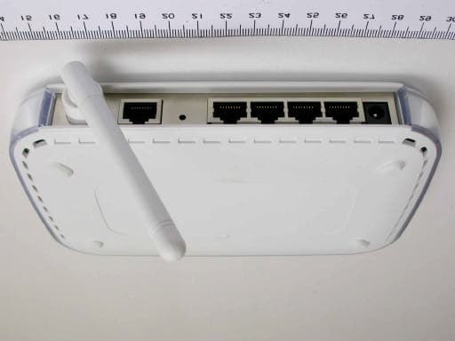
Click to zoom
Application Details
- Equipment Class
- DTS - Digital Transmission System
- Date of Grant
- Aug 15, 2004
- Application Purpose
- Original Equipment
- Date of Application
- Aug 15, 2004
- Equipment Note
- Wireless Router
- Frequency Range
- 2412.00000000 - 2462.00000000
- Company
- Netgear Incorporated
- Country
- United States
Documents & Files
Document Text
Text extracted from the exhibit documents filed with the FCC. Open a document above to read the original.
Users Manual
202-10039-01 202-10039-01 Version 1.0 June 2004 NETGEAR, Inc. 4500 Great America Parkway Santa Clara, CA 95054 USA Reference Manual for the MR814 v3 Cable/DSL Wireless Router DECLARATION OF CON”FORMITY Per FCC Part 15 Section 15.19(a) (3) Responsible Party Name: Netgear Incorporation Address: 4500 Great America Parkway, Santa Clara, California 95054 USA Phone/Fax No: +1-408-907-8000 / +1-408-907-8097 Hereby declares that the product Product Name: Wireless Router Model Number: MR814v3 © 2004 by NETGEAR, Inc. All rights reserved. June 2004. Trademarks NETGEAR is a trademark of Netgear, Inc. Microsoft, Windows, and Windows NT are registered trademarks of Microsoft Corporation. Other brand and product names are registered trademarks or trademarks of their respective holders. Statement of Conditions In the interest of improving internal design, operational function, and/or reliability, NETGEAR reserves the right to make changes to the products described in this document without notice. NETGEAR does not assume any liability that may occur due to the use or application of the product(s) or circuit layout(s) described herein. Federal Communications Commission (FCC) Compliance Notice: Radio Frequency Notice This equipment has been tested and found to comply with the limits for a Class B digital device, pursuant to part 15 of the FCC Rules. These limits are designed to provide reasonable protection against harmful interference in a residential installation. This equipment generates, uses, and can radiate radio frequency energy and, if not installed and used in accordance with the instructions, may cause harmful interference to radio communications. However, there is no guarantee that interference will not occur in a particular installation. If this equipment does cause harmful interference to radio or television reception, which can be determined by turning the equipment off and on, the user is encouraged to try to correct the interference by one or more of the following measures: •Reorient or relocate the receiving antenna. •Increase the separation between the equipment and receiver. •Connect the equipment into an outlet on a circuit different from that to which the receiver is connected. •Consult the dealer or an experienced radio/TV technician for help. EN 55 022 Declaration of Conformance This is to certify that the MR814 v3 Cable/DSL Wireless Router is shielded against the generation of radio interference in accordance with the application of Council Directive 89/336/EEC, Article 4a. Conformity is declared by the application of EN 55 022 Class B (CISPR 22). FCC Radiation Exposure Statement This equipment complies with FCC RF radiation exposure limits set forth for an uncontrolled environment. This equipment should be installed and operated with a minimum distance of 20 centimeters between the radiator and your body. This device complies with Part 15 of the FCC Rules. Operation is subject to the following two conditions: (1) This device may not cause harmful interference, and (2) This device must accept any interference received, including interference that may cause undesired operation. This transmitter must not be co-located or operating in conjunction with any other antenna or transmitter. 202-10039-01 iii Bestätigung des Herstellers/Importeurs Es wird hiermit bestätigt, daß das MR814 v3 Cable/DSL Wireless Router gemäß der im BMPT-AmtsblVfg 243/1991 und Vfg 46/1992 aufgeführten Bestimmungen entstört ist. Das vorschriftsmäßige Betreiben einiger Geräte (z.B. Testsender) kann jedoch gewissen Beschränkungen unterliegen. Lesen Sie dazu bitte die Anmerkungen in der Betriebsanleitung. Das Bundesamt für Zulassungen in der Telekommunikation wurde davon unterrichtet, daß dieses Gerät auf den Markt gebracht wurde und es ist berechtigt, die Serie auf die Erfüllung der Vorschriften hin zu überprüfen. Certificate of the Manufacturer/Importer It is hereby certified that the MR814 v3 Cable/DSL Wireless Router has been suppressed in accordance with the conditions set out in the BMPT-AmtsblVfg 243/1991 and Vfg 46/1992. The operation of some equipment (for example, test transmitters) in accordance with the regulations may, however, be subject to certain restrictions. Please refer to the notes in the operating instructions. Federal Office for Telecommunications Approvals has been notified of the placing of this equipment on the market and has been granted the right to test the series for compliance with the regulations. Voluntary Control Council for Interference (VCCI) Statement This equipment is in the second category (information equipment to be used in a residential area or an adjacent area thereto) and conforms to the standards set by the Voluntary Control Council for Interference by Data Processing Equipment and Electronic Office Machines aimed at preventing radio interference in such residential areas. When used near a radio or TV receiver, it may become the cause of radio interference. Read instructions for correct handling. Customer Support Refer to the Support Information Card that shipped with your MR814 v3 Cable/DSL Wireless Router. World Wide Web NETGEAR maintains a World Wide Web home page that you can access at the universal resource locator (URL) http://www.netgear.com. A direct connection to the Internet and a Web browser such as Internet Explorer or Netscape are required. Contentsv 202-10039-01 Contents Chapter 1 About This Manual Audience, Scope, Conventions, and Formats ................................................................1-1 How to Use This Manual ................................................................................................1-2 How to Print this Manual .................................................................................................1-3 Chapter 2 Introduction Key Features of the Router ............................................................................................2-1 802.11b Standards-based Wireless Networking ........................…
Text truncated - open the document above for the full version.
Users Manual
Reference Manual for the MR814 v3 Cable/DSL Wireless Router 6-4Maintenance 202-10039-01 Click on the “Show Statistics” button to display router usage statistics, as shown below. Figure 6-3: Router Statistics screen This screen shows the following statistics: Table 6-3:Router Statistics Items ItemDescription PortThe statistics for the WAN (Internet) and LAN (local) ports. For each port, the screen displays: StatusThe link status of the port. TxPktsThe number of packets transmitted on this port since reset or manual clear. RxPktsThe number of packets received on this port since reset or manual clear. CollisionsThe number of collisions on this port since reset or manual clear. Tx B/sThe current transmission (outbound) bandwidth used on the WAN and LAN ports. Rx B/sThe current reception (inbound) bandwidth used on the WAN and LAN ports. Up TimeThe amount of time since the router was last restarted. Up TimeThe time elapsed since this port acquired the link. Poll IntervalSpecifies the intervals at which the statistics are updated in this window. Click on Stop to freeze the display. Set IntervalEnter a time and click the button to set the polling frequency. StopClick the Stop button to freeze the polling information. Reference Manual for the MR814 v3 Cable/DSL Wireless Router Maintenance6-5 202-10039-01 Viewing a List of Attached Devices The Attached Devices menu contains a table of all IP devices that the router has discovered on the local network. From the Main Menu of the browser interface, under the Maintenance heading, select Attached Devices to view the table, shown below. Figure 6-4: Attached Devices menu For each device, the table shows the IP address, NetBIOS Host Name (if available), and Ethernet MAC address. Note that if the router is rebooted, the table data is lost until the router rediscovers the devices. To force the router to look for attached devices, click the Refresh button. Configuration File Management The configuration settings of the MR814 v3 router are stored within the router in a configuration file. This file can be saved (backed up) to a user’s PC, retrieved (restored) from the user’s PC, or cleared to factory default settings. Reference Manual for the MR814 v3 Cable/DSL Wireless Router 6-6Maintenance 202-10039-01 From the Main Menu of the browser interface, under the Maintenance heading, select the Settings Backup heading to bring up the menu shown below. Figure 6-5: Settings Backup menu Three options are available, and are described in the following sections. Restoring and Backing Up the Configuration The Restore and Backup options in the Settings Backup menu allow you to save and retrieve a file containing your router’s configuration settings. To save your settings, select the Backup tab. Click the Backup button. Your browser will extract the configuration file from the router and will prompt you for a location on your PC to store the file. You can give the file a meaningful name at this time, such as pacbell.cfg. To restore your settings from a saved configuration file, enter the full path to the file on your PC or click the Browse button to browse to the file. When you have located it, click the Restore button to send the file to the router. The router will then reboot automatically. Reference Manual for the MR814 v3 Cable/DSL Wireless Router Maintenance6-7 202-10039-01 Erasing the Configuration It is sometimes desirable to restore the router to a known blank condition. This can be done by using the Erase function, which will restore all factory settings. After an erase, the router's password will be password, the LAN IP address will be 192.168.0.1, and the router's DHCP client will be enabled. To erase the configuration, click the Erase button. To restore the factory default configuration settings without knowing the login password or IP address, you must use the Default Reset button on the rear panel of the router. See “Restoring the Default Configuration and Password” on page 8-7. Upgrading the Router Software The routing software of the MR814 v3 router is stored in FLASH memory, and can be upgraded as new software is released by NETGEAR. Upgrade files can be downloaded from Netgear's Web site. If the upgrade file is compressed (.ZIP file), you must first extract the binary (.BIN) file before sending it to the router. The upgrade file can be sent to the router using your browser. Note: The Web browser used to upload new firmware into the MR814 v3 router must support HTTP uploads. NETGEAR recommends using Microsoft Internet Explorer or Netscape Navigator 3.0 or above. Note: Before upgrading the router software, use the router backup utility to save your configuration settings. Any router upgrade will revert the router settings back to the factory defaults. After completing the upgrade, you can restore your settings from the backup. Reference Manual for the MR814 v3 Cable/DSL Wireless Router 6-8Maintenance 202-10039-01 From the Main Menu of the browser interface, under the Maintenance heading, select the Router Upgrade heading to display the menu shown below. Figure 6-6: Router Upgrade menu To upload new firmware: 1.Download and unzip the new software file from NETGEAR. 2.In the Router Upgrade menu, click the Browse button and browse to the location of the binary (.BIN) upgrade file 3.Click Upload. Note: When uploading software to the MR814 v3 router, it is important not to interrupt the Web browser by closing the window, clicking a link, or loading a new page. If the browser is interrupted, it may corrupt the software. When the upload is complete, your router will automatically restart. The upgrade process will typically take about one minute. In some cases, you may need to reconfigure the router after upgrading. Changing the Administrator Password Note: Before changing the router password, use the router backup utility to save your configuration settings. If after changing the password, you forget the new password you assigned, you will have to reset the route…
Text truncated - open the document above for the full version.
Cover Letter(s)
American Telecommunications Certification Body Inc. 6731 Whittier Ave, McLean, VA 22101 August 7, 2004 RE: Netgear Inc. FCC ID: PY3MR814V3 After a review of the submitted information, I have a few comments on the above referenced Application. 1) Please provide a higher resolution label exhibit. The FCC ID must be easily readable. 2) Please confirm that a DoC has been performed for this device using an accredited test lab and the minimum test configuration per ANSI C63.4. 3) Please clarify if you are asking for: a) Certification of the device as a TX, and a DoC has been performed by an appropriately accredited test lab for a PC peripheral b) Certification as a TX + PC peripheral. Note 1: The option b) would be considered as a composite application and 2 certificates (one for the TX, one for the PC peripheral portion) would be issued. There are additional review costs associated with this additional certification. Note 2: to qualify to perform DoC applications, the test lab must be accredited (i.e. NVLAP or A2LA) to perform testing under the DoC procedure. ECC does not appear as an accredited test lab on the FCC site. Please explain. Note 3: Note that for DoC tests, the device is configured with a minimum test configuration as specified by ANSI C63.4 which includes complete computer + 2 I/O devices attached (one may be the EUT). Note 4: For the remaining part of this review, it is assumed that the device is being approved under a DoC for the PC peripheral portion. --- Continued on Next Page --- z Page 2 August 7, 2004 4) If the device is also been approved using a DoC, then the users manual must include the following on a single page: COMPLIANCE INFORMATION FOR DoC AUTHORIZATIONS (47CFR 2.1077) If a product is tested and authorized under a Declaration of Conformity, a compliance information statement shall be supplied with the product at the time of marketing or importation, containing the following information on a single page : (1) Identification of the product, i.e. name and model number. (2) A statement similar to that contained in Section 15.19(a)(3) that the product complies with Part 15 of the regulations. (3) The identification, by name, address and telephone number, of the responsible party. The responsible party is defined as either the manufacturer, or if the equipment is imported, the importer. The responsible party for a Declaration of Conformity must be located within the United States. 5) The test report mentions that radiated emissions were taken at 10 meters (page 16). However this is only allowed for < 1 GHz testing. Please explain what test distance was used for > 1 GHz. 6) It appears that only one channel was tested for radiated emissions. The FCC expects a Low, Middle, and High channel to be tested. 7) Data for > 1 GHz on pages 33 meet the 74 dBuV/m limit. However, there is also an average limit of 54 dBuV/m (RBW = 1 MHz, VBW >= 10 Hz, assuming 100% continuous TX) that must be met. Compliance to both limits must be shown. 8) The data shown on pages 45 appears to actually be average data from the plots and not peak data. The tables should be corrected. Timothy R. Johnson Examining Engineer mailto: [email protected] The items indicated above must be submitted before processing can continue on the above referenced application. Failure to provide the requested information may result in application termination. Correspondence should be considered part of the permanent submission and may be viewed from the Internet after a Grant of Equipment Authorization is issued. Please do not respond to this correspondence using the email reply button. In order for your response to be processed expeditiously, you must submit your documents through the AmericanTCB.com website. Also, please note that partial responses increase processing time and should not be submitted. Any questions about the content of this correspondence should be directed to the sender.
Cover Letter(s)
American Telecommunications Certification Body Inc. 6731 Whittier Ave, McLean, VA 22101 August 16, 2004 RE: Netgear Inc. FCC ID: PY3MR814V3 After a review of the submitted information, I have a few comments on the above referenced Application. 1) FYI.....The DoC information should include the statements from Section 15.19(a)(3), not simply a reference to this paragraph. Note the user does not typically have Part 15 themselves. Please be sure the manufacturer corrects this. Timothy R. Johnson Examining Engineer mailto: [email protected] The items indicated above must be submitted before processing can continue on the above referenced application. Failure to provide the requested information may result in application termination. Correspondence should be considered part of the permanent submission and may be viewed from the Internet after a Grant of Equipment Authorization is issued. Please do not respond to this correspondence using the email reply button. In order for your response to be processed expeditiously, you must submit your documents through the AmericanTCB.com website. Also, please note that partial responses increase processing time and should not be submitted. Any questions about the content of this correspondence should be directed to the sender.
Cover Letter(s)
Hi, Timothy I 've re-loaded 3 files (Label & Location new, test report 1&2) to your website, please check them out. The DoC report of this device has been performed by an accredited test lab, and tested configuration per ANSI C63.4. We just only asking for certification of the device as a TX. Thank you. ³ ̄¥HÛr Ivy Chen ¼s¾s¬ì§ÞªÑ¥÷¦³¤½¥q Exclusive Certification Corporation Page 1 of 1Ivy Chen, 05:10 PM 8/10/2004 +0800, modification of FCC ID: PY3MR814V3 8/16/2004Printed for "Timothy R. Johnson" <[email protected]>
ID Label/Location Info
Size Location:
RF Exposure Info
1.1. Test Result of RF Exposure Evaluation Product : Wireless Router Test Item : RF Exposure Evaluation data Test site : OATSI-SD Test Mode : 802.11b 1.1.1. Antenna Gain The maximum Gain is 1.8 dBi. 1.1.2. EUT Operation condition Software provided by client enabled the EUT to transmit and receive data at lowest, middle and highest channel individually. 1.1.3. Output Power into Antenna & RF Exposure Evaluation Distance Modulation Standard: IEEE 802.11b Test Date: Jul. 21, 2004 Temperature: 25 Humidity: 61 Channel Channel Frequency (MHz) Output Power to Antenna (dBm) Power Density(S) (mW/Cm 2 ) 01 2412 19.57 0.0273 06 2437 19.27 0.0255 11 2462 18.92 0.0235 The MPE is calculated as 0.0273 mW / cm 2 < limit 1 mW / cm 2 . So, RF exposure limit warning or SAR test are not required..
Test Report
Exclusive Certification Corp. Tel:886-2-2792-3366 Fax:886-2-2792-1100 Issued date: Jul. 26, 2004 1 of 54 FCC ID: PY3MR814V3 FCC Test Report: FI04072101-A FCC TEST REPORT according to FCC Rules and Regulations Part 15 Subpart C † The test result refers exclusively to the test presented test model / sample., † Without written approval of Exclusive Certification Corp. the test report shall not be reproduced except in full. Applicant NETGEAR Inc. Address 4500 Great America Parkway Santa Clara California 95054 USA Equipment Wireless Router Model No. MR814v3 FCC ID PY3MR814V3 Trade Name NETGEAR Exclusive Certification Corp. Tel:886-2-2792-3366 Fax:886-2-2792-1100 Issued date: Jul. 26, 2004 2 of 54 FCC ID: PY3MR814V3 FCC Test Report: FI04072101-A Contents 1. Report of Measurements and Examinations..................................................................................4 1.1. List of Measurements and Examinations.............................................................................4 1.2. Antenna Requirements......................................................................................................5 1.3. Test of Conducted Emission...............................................................................................6 1.4. Test of Radiated Emission.................................................................................................8 1.5. 6dB Bandwidth.................................................................................................................9 1.6. Maximum Peak Output Power............................................................................................9 1.7. Band Edges Measurement..............................................................................................10 1.8. Power Spectral Density...................................................................................................10 1.9. Restricted Bands of Operation.........................................................................................11 1.10. Labeling Requirement.....................................................................................................11 1.11. RF Exposure..................................................................................................................12 2. Test Configuration of Equipment under Test................................................................................14 2.1. Test Mode and Test Software...........................................................................................14 2.2. Description of Test System..............................................................................................14 2.3. Connection Diagram of Test System.................................................................................15 2.4. Feature of Equipment under Test.....................................................................................15 2.5. History of this test report..................................................................................................15 3. General Information of Test........................................................................................................16 4. Test Result and Data.................................................................................................................17 4.1. Antenna Requirement.....................................................................................................17 4.2. Test Result of Conducted Emission..................................................................................18 4.3. RF Portion......................................................................................................................27 4.4. 6dB Bandwidth Measurement Data..................................................................................37 4.5. Peak Output Power Measurement Data............................................................................40 4.6. Band Edges Measurement Data......................................................................................43 4.7. Power Spectral Density Measurement Data......................................................................50 4.8. Test Result of RF Exposure Evaluation.............................................................................53 5. List of Measuring Equipment Used.............................................................................................54 Appendix A. Photographs of EUT........................................................................ .............A1 ~ A6 Exclusive Certification Corp. Tel:886-2-2792-3366 Fax:886-2-2792-1100 Issued date: Jul. 26, 2004 3 of 54 FCC ID: PY3MR814V3 FCC Test Report: FI04072101-A CERTIFICATE OF COMPLIANCE according to FCC Rules and Regulations Part 15 Subpart C Applicant NETGEAR Inc. Address 4500 Great America Parkway Santa Clara California 95054 USA Equipment Wireless Router Model No. MR814v3 FCC ID NETGEAR I HEREBY CERTIFY THAT : The measurements shown in this test report were made in accordance with the procedures given in ANSI C63.4. The equipment was passéd the test performed according to FCC Rules and Regulations Part 15 Subpart C (2002). The test was carried out on Jul. 25, 2004 at Exclusive Certification Corp. Signature Anson Chou / Manager Exclusive Certification Corp. Tel:886-2-2792-3366 Fax:886-2-2792-1100 Issued date: Jul. 26, 2004 4 of 54 FCC ID: PY3MR814V3 FCC Test Report: FI04072101-A 1. Report of Measurements and Examinations 1.1. List of Measurements and Examinations FCC Rule . Description of Test Result 15.203 . Antenna Requirement Pass 15.207 . Conducted Emission Pass 15.209 . Radiated Emission Pass 15.247(a)(2) . 6dB Bandwidth Pass 15.247(b) . Maximum Peak Output Power Pass 15.247(c) . 100kHz Bandwidth of Frequency Band Edges Pass 15.247(d) . Power Spectral Density Pass 1.1307 1.1310 2.1091 2.1093 . RF Exposure Compliance Pass Test by: Exclusive Certification Corp. Tel:886-2-2792-3366 Fax:886-2-2792-1100 Issued d…
Text truncated - open the document above for the full version.
Test Report
Exclusive Certification Corp. Tel:886-2-2792-3366 Fax:886-2-2792-1100 Issued date: Jul. 26, 2004 27 of 54 FCC ID: PY3MR814V3 FCC Test Report: FI04072101-A 4.3. RF Portion 4.3.1. Test Result of Conducted Emission Exclusive Certification Corp. Tel:886-2-2792-3366 Fax:886-2-2792-1100 Issued date: Jul. 26, 2004 28 of 54 FCC ID: PY3MR814V3 FCC Test Report: FI04072101-A Exclusive Certification Corp. Tel:886-2-2792-3366 Fax:886-2-2792-1100 Issued date: Jul. 26, 2004 29 of 54 FCC ID: PY3MR814V3 FCC Test Report: FI04072101-A 4.3.2. Test Result of Radiated Emission Exclusive Certification Corp. Tel:886-2-2792-3366 Fax:886-2-2792-1100 Issued date: Jul. 26, 2004 30 of 54 FCC ID: PY3MR814V3 FCC Test Report: FI04072101-A Exclusive Certification Corp. Tel:886-2-2792-3366 Fax:886-2-2792-1100 Issued date: Jul. 26, 2004 31 of 54 FCC ID: PY3MR814V3 FCC Test Report: FI04072101-A Exclusive Certification Corp. Tel:886-2-2792-3366 Fax:886-2-2792-1100 Issued date: Jul. 26, 2004 32 of 54 FCC ID: PY3MR814V3 FCC Test Report: FI04072101-A Test by: Exclusive Certification Corp. Tel:886-2-2792-3366 Fax:886-2-2792-1100 Issued date: Jul. 26, 2004 33 of 54 FCC ID: PY3MR814V3 FCC Test Report: FI04072101-A Modulation Standard: IEEE 802.11b Channel 1 a) Emission frequencies below 1 GHz Test Date: Jul. 21, 2004 Temperature: 25 Humidity: 61 Frequency (MHz) Ant-Pol H/V Meter Reading (dBuV) Corrected Factor (dB) Result@3m (dBuV/m) Limit@3m (dBuV/m) Margin (dB) Table Deg. Ant High (m) 397.63 H 49.98 -9.16 40.82 46 -5.18 270 1.5 924.34 H 37.22 3.66 40.88 46 -5.12 200 1.0 252.13 V 54.60 -13.40 41.20 46 -4.80 180 1.5 924.34 V 39.02 3.66 42.68 46 -3.32 200 1.4 Notes: 1. Result = Meter Reading + Corrected Factor 2. Corrected Factor = Antenna Factor + Cable Loss – Amplifier b) Emission frequencies above 1 GHz Frequency (MHz) Ant-Pol H/V Meter Reading (dBuV) Corrected Factor (dB) Result@3m (dBuV/m) Limit@3m (dBuV/m) Margin (dB) Remark Table Deg. Ant High (m) 1736.40 H 53.98 -3.52 50.46 74 -23.54 Peak 210 1.5 1736.40 H 41.65 -3.52 38.13 54 -15.87 Ave 190 1.5 1722.40 V 65.68 -4.20 61.48 74 -12.52 Peak 200 1.5 1722.40 V 50.23 -4.20 46.03 54 -7.97 Ave 210 1.5 1786.80 V 65.98 -3.83 62.18 74 -11.82 Peak 190 1.0 1786.80 V 50.79 -3.83 46.96 54 -7.04 Ave 200 1.0 1952.00 V 63.87 -2.89 60.98 74 -13.02 Peak 180 1.5 1952.00 V 49.02 -2.89 46.13 54 -7.87 Ave 190 1.5 2896.00 V 57.55 0.53 58.08 74 -15.92 Peak 190 1.5 2896.00 V 42.13 0.53 42.66 54 -11.34 Ave 180 1.5 4805.00 V 57.31 6.82 64.13 74 -9.87 Peak 280 1.5 4805.00 V 40.35 6.82 47.17 54 -6.83 Ave 270 1.5 Exclusive Certification Corp. Tel:886-2-2792-3366 Fax:886-2-2792-1100 Issued date: Jul. 26, 2004 34 of 54 FCC ID: PY3MR814V3 FCC Test Report: FI04072101-A Modulation Standard: IEEE 802.11b Channel 6 a) Emission frequencies below 1 GHz Test Date: Jul. 21, 2004 Temperature: 25 Humidity: 61 Frequency (MHz) Ant-Pol H/V Meter Reading (dBuV) Corrected Factor (dB) Result@3m (dBuV/m) Limit@3m (dBuV/m) Margin (dB) Table Deg. Ant High (m) 397.63 H 50.13 -9.16 40.97 46 -5.03 270 1.5 924.34 H 37.12 3.66 40.78 46 -5.22 210 1.0 252.13 V 54.58 -13.40 41.18 46 -4.82 180 1.5 924.34 V 39.08 3.66 42.74 46 -3.26 190 1.4 Notes: 1. Result = Meter Reading + Corrected Factor 2. Corrected Factor = Antenna Factor + Cable Loss – Amplifier b) Emission frequencies above 1 GHz Frequency (MHz) Ant-Pol H/V Meter Reading (dBuV) Corrected Factor (dB) Result@3m (dBuV/m) Limit@3m (dBuV/m) Margin (dB) Remark Table Deg. Ant High (m) 1736.40 H 54.99 -3.52 51.47 74 -22.53 Peak 200 1.5 1736.40 H 42.85 -3.52 39.33 54 -14.67 Ave 190 1.5 1722.40 V 66.47 -4.20 62.27 74 -11.73 Peak 190 1.5 1722.40 V 51.08 -4.20 46.88 54 -7.12 Ave 200 1.5 1786.80 V 67.23 -3.83 63.40 74 -10.60 Peak 190 1.0 1786.80 V 51.66 -3.83 47.83 54 -6.17 Ave 200 1.0 1952.00 V 64.87 -2.89 61.98 74 -12.02 Peak 190 1.5 1952.00 V 50.76 -2.89 47.87 54 -6.13 Ave 190 1.5 2896.00 V 58.46 0.53 58.99 74 -15.01 Peak 200 1.5 2896.00 V 43.13 0.53 43.66 54 -10.34 Ave 180 1.5 4855.00 V 58.27 6.82 65.09 74 -8.91 Peak 300 1.5 4855.00 V 41.38 6.82 48.20 54 -5.80 Ave 280 1.5 Exclusive Certification Corp. Tel:886-2-2792-3366 Fax:886-2-2792-1100 Issued date: Jul. 26, 2004 35 of 54 FCC ID: PY3MR814V3 FCC Test Report: FI04072101-A Modulation Standard: IEEE 802.11b Channel 11 a) Emission frequencies below 1 GHz Test Date: Jul. 21, 2004 Temperature: 25 Humidity: 61 Frequency (MHz) Ant-Pol H/V Meter Reading (dBuV) Corrected Factor (dB) Result@3m (dBuV/m) Limit@3m (dBuV/m) Margin (dB) Table Deg. Ant High (m) 397.63 H 50.30 -9.16 41.14 46 -4.86 270 1.5 924.34 H 37.37 3.66 41.03 46 -4.97 200 1.0 252.13 V 54.64 -13.40 41.24 46 -4.76 180 1.5 924.34 V 39.08 3.66 42.74 46 -3.26 190 1.4 Notes: 1. Result = Meter Reading + Corrected Factor 2. Corrected Factor = Antenna Factor + Cable Loss – Amplifier b) Emission frequencies above 1 GHz Frequency (MHz) Ant-Pol H/V Meter Reading (dBuV) Corrected Factor (dB) Result@3m (dBuV/m) Limit@3m (dBuV/m) Margin (dB) Remark Table Deg. Ant High (m) 1733.60 H 54.49 -3.52 50.97 74 -23.03 Peak 180 1.5 1733.60 H 42.60 -3.52 39.08 54 -14.92 Ave 190 1.5 1736.40 H 56.02 -3.52 52.50 74 -21.50 Peak 200 1.5 1736.40 H 43.98 -3.52 40.46 54 -13.54 Ave 190 1.5 1722.40 V 67.71 -4.20 63.51 74 -10.49 Peak 200 1.5 1722.40 V 52.13 -4.20 47.93 54 -6.07 Ave 210 1.5 1786.80 V 68.60 -3.83 64.77 74 -9.23 Peak 190 1.0 1786.80 V 52.87 -3.83 49.04 54 -4.96 Ave 200 1.0 1952.00 V 66.06 -2.89 63.17 74 -10.83 Peak 180 1.5 1952.00 V 51.10 -2.89 48.21 54 -5.79 Ave …
Text truncated - open the document above for the full version.
Contact Information
Applicant
David Kay
Technical Contact
Exclusive Certification Corp.Ivy Chen
[email protected]+886-2-2792-3366
4F-2, No.28, Lane 78, Xing-Ai Road · Taipei City · Taiwan
Non-Technical Contact
Netgear Inc.Lily Chang
[email protected]+886-2-2656-2055
Test Firm
ECOM Sertech Corp.C. Wu
Technical Specifications
| # | Rule Parts | Frequency Range | Power Output |
|---|---|---|---|
| 1 | 15C | 2.41 GHz - 2.46 GHz | 91.00 mW |
Other Applications from Netgear Incorporated

PY325100647
Aug 04, 2026BE5000 Dual-Band PoE 2.5G Insight Managed WiFi 7 Outdoor Access Point
Equipment Class
DTS - Digital Transmission SystemPY325300652
May 12, 2026BE5000 Dual-Band PoE 2.5G Insight Managed WiFi 7 Access Point
Equipment Class
NII - Unlicensed National Information Infrastructure TXPY325400656
Apr 16, 2026Orbi Outdoor Satellite
Equipment Class
DTS - Digital Transmission SystemPY324400640
Dec 12, 2025Orbi 11BE WiFi 7 Tri-band Router, Orbi 11BE WiFi 7 Tri-band Satellite
Equipment Class
NII - Unlicensed National Information Infrastructure TXPY324100618
Jul 31, 2024Nighthawk 5G Mobile Router
Equipment Class
PCB - PCS Licensed Transmitter