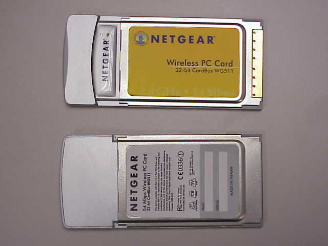
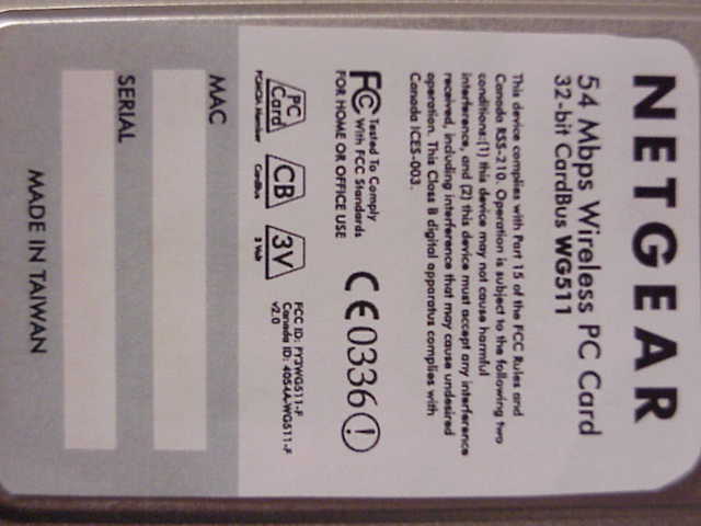
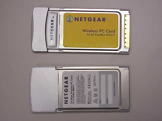
PY3WG511-F2.4 GHz 802.11g WLAN Cardbus card
Netgear Incorporated
Click to zoom
Application Details
- Equipment Class
- DTS - Digital Transmission System
- Date of Grant
- May 20, 2003
- Application Purpose
- Original Equipment
- Date of Application
- May 20, 2003
- Equipment Note
- 2.4 GHz 802.11g WLAN Cardbus card
- Frequency Range
- 2412.00000000 - 2462.00000000
- Company
- Netgear Incorporated
- Country
- United States
Documents & Files
Document Text
Text extracted from the exhibit documents filed with the FCC. Open a document above to read the original.
Users Manual
The basic installation and configuration instructions below assume that your wireless network connection will be to an access point, and you are not using WEP security. Please refer to Reference Manual on the Resource CD for detailed instructions on configuring WEP, using Ad-hoc mode, or using advanced options. Windows XP Basic Installation 1. First, install the WG511 software. a. Power on your notebook, let the operating system boot up completely, and log in as needed. b. Insert the Resource CD for the WG511 into your CD-ROM drive. The CD main page shown below will load. c. Click the Install Driver & Utility link. d. Follow the InstallShield Wizard steps, and click Finish when done to restart your computer. 2. Next, install the WG511 Wireless PC Card. a.Hold the PC Card with the Netgear logo facing up and insert it into a CardBus slot. After a short delay, the Found New Hardware Wizard displays. You will see the WG511 system tray icon on the lower right portion of the Windows task bar. 3. Now, configure your WG511. a. Right click on the network icon in the Windows XP system tray to open the network options menu. b. Click on the View Available Wireless Networks menu item. c. Click on the “Allow me to connect to the selected wireless network even though this is not secure” check box. d. Click Connect. 4. Finally, verify wireless network connectivity. a. Open the WG511 utility by clicking on the icon in the Windows system tray. b. Verify that your Connection and Status Monitor information matches your wireless network. c. Check the two LEDs on the WG511: green indicates a good connection; blinking green indicates attempting to connect; off indicates the card is not fully plugged in. Blinking for the amber LED indicates data transmission. d. Verify connectivity to the Internet or network resources. Note: If you are unable to connect, see troubleshooting tips in the Basic Installation section of the Reference Manual on the NETGEAR 54 Mbps Wireless PC Card WG511 Resource CD. WG511 54 Mbps Wireless PC Card Quick Installation Guide Follow these quick steps to install your WG511 Note: If a Windows XP logo testing warning appears, click Continue Anyway to proceed. Windows XP will display a Wireless Network Connec- tion message like this one. If there is more than one wireless network in your vicinity, click on the one to which you will connect. Note: When the Window XP wireless configuration utility is selected, only these two tab pages appear. To use the full Netgear utility, please see the Reference Manual on the NETGEAR 54 Mbps Wireless PC Card WG511 Resource CD. Windows 2000, Me/98 Installation 1. First, install the WG511 software. a. Power on your notebook, let the operating system boot up completely, and log in as needed. b. Insert the Resource CD for the WG511 into your CD-ROM drive. The CD main page shown below will load. c. Click the Install Driver & Utility link. d. Follow the InstallShield Wizard steps, and click Finish when done to restart your computer. 2. Next, install the WG511 Wireless PC Card. a.Hold the PC Card with the Netgear logo facing up and insert it into a CardBus slot. After a short delay, the Found New Hardware Wizard displays. You will now see the WG511 system tray icon in the lower right area of the Windows task bar. 3. Now, configure your WG511 and save the Profile. a. Open the WG511 utility by clicking on the icon in the Windows system tray. The utility opens to the Configuration tab page. b. Change the Network Name SSID to match your network. Tip: As an alternative to typing in the SSID, you can use the Site Survey tab to view the available wireless networks, choose the one you want, and click the Connect button. c. Click the Profile tab. Enter a name for your profile. d. Click the Save button to save all your settings in the Profile, and then click the Activate button. You can save multiple profiles and activate whichever one you need to use. Tip: If you use your notebook PC to connect to a wireless network at work and at home, create profiles called work and home. Then, activate whichever one you need for wherever you are located. 4. Finally, verify wireless network connectivity. a. Click the Status tab page. b. Verify that your Connection and Status Monitor information matches your wireless network. c. Check the two LEDs on the WG511: green indicates a good connection; blinking green indicates attempting to connect; off indicates the card is not fully plugged in. Blinking for the amber LED indicates data transmission. d. Verify connectivity to the Internet or network resources. Note: If you are unable to connect, see troubleshooting tips in the Basic Installation section of the Reference Manual on the NETGEAR 54 Mbps Wireless PC Card WG511 Resource CD. ©2003 by NETGEAR, Inc. All rights reserved. NETGEAR, the Netgear logo, The Gear Guy and Everybody's Connecting are trademarks or registered trademarks of Netgear, Inc. in the United States and/or other countries. Microsoft and Windows are registered trademarks of Microsoft Corporation in the United States and/or other countries. Other brand and prod- uct names are trademarks or registered trademarks of their respective holders. Information is subject to change without notice. All rights reserved. Note: If Windows 2000 displays a Digital Signature Not Found warning, click Ye s to continue the installation. These are the default settings. Note: You can also use the Site Survey tab to verify the availability of wireless networks and their SSIDs. Please see the Reference Manual on the NETGEAR 54 Mbps Wireless PC Card WG511 Resource CD.
Users Manual
M0-WG511NA-0 Version v1.0 May 2003 NETGEAR, Inc. 4500 Great America Parkway Santa Clara, CA 95054 USA Installation Guide for the NETGEAR 54 Mbps Wireless PC Card WG511 ii Technical Support Please refer to the support information card that shipped with your product. By registering your product at www.netgear.com/register , we can provide you with faster expert technical support and timely notices of product and software upgrades. NETGEAR, INC. Support Information Phone: 1-888-NETGEAR, for US & Canada only. For other countries, see your Support information card. E-mail: [email protected] Web site: www.netgear.com Statement of Conditions In the interest of improving internal design, operational function, and/or reliability, NETGEAR reserves the right to make changes to the products described in this document without notice. NETGEAR does not assume any liability that may occur due to the use or application of the product(s) or circuit layout(s) described herein. ©2003 NETGEAR, Inc. NETGEAR, the Netgear logo, The Gear Guy and Everybody's Connecting are trademarks or registered trademarks of Netgear, Inc. in the United States and/or other countries. Microsoft and Windows are registered trademarks of Microsoft Corporation in the United States and/or other countries. Other brand and product names are trademarks or registered trademarks of their respective holders. Information is subject to change without notice. All rights reserved . May 2003 Certificate of the Manufacturer/Importer It is hereby certified that the Model WG511 Wireless PC Card has been suppressed in accordance with the conditions set out in the BMPT- AmtsblVfg 243/1991 and Vfg 46/1992. The operation of some equipment (for example, test transmitters) in accordance with the regulations may, however, be subject to certain restrictions. Please refer to the notes in the operating instructions. Federal Office for Telecommunications Approvals has been notified of the placing of this equipment on the market and has been granted the right to test the series for compliance with the regulations. VCCI Statement This equipment is in the Class B category (information equipment to be used in a residential area or an adjacent area thereto) and conforms to the standards set by the Voluntary Control Council for Interference by Data Processing iii Equipment and Electronic Office Machines aimed at preventing radio interference in such residential areas. When used near a radio or TV receiver, it may become the cause of radio interference. Read instructions for correct handling. FCC Information to User This product does not contain any user serviceable components and is to be used with approved antennas only. Any product changes or modifications will invalidate all applicable regulatory certifications and approvals FCC Guidelines for Human Exposure In order to comply with RF exposure limits established in the ANSI C95.1 standards, the user is advised to maintain a distance of at least 1 inch (2.5 cm) from the antenna of this device while it is in use. FCC Electronic Emission Notices This device complies with part 15 of the FCC Rules. Operation is subject to the following two conditions: 1.This device may not cause harmful interference 2.This device must accept any interference received, including interference that may cause undesired operation. FCC Radio Frequency Interference Statement This equipment has been tested and found to comply with the limits for a class B digital device, pursuant to Part 15 of the FCC Rules. These limits are designed to provide reasonable protection against harmful interference when the equipment is operated in a commercial environment. This equipment generates, uses and can radiate radio frequency energy and, if not installed and used in accordance with the instructions, may cause harmful interference to radio communications. Operation of this equipment in a residential area may cause harmful interference, in which case the user will be required to correct the interference at his own expense. If this equipment does cause harmful interference to radio or television reception, which can be determined by turning the equipment off and on, the user is encouraged to try to correct the interference by one or more of the following measures: NETGEAR 54 Mbps Wireless PC Card WG511 FOR HOME OR OFFICE USE Tested to Comply with FCC Standards iv •Reorient or relocate the receiving antenna •Increase the separation between the equipment and receiver •Connect the equipment into an outlet on a circuit different from that to which the receiver is connected •Consult the dealer or an experienced radio/TV technician for help Export Restrictions This product or software contains encryption code which may not be exported or transferred from the US or Canada without an approved US Department of Commerce export license. Europe - EU Declaration of Conformity This device complies with the essential requirements and other relevant provisions of the European R&TTE Directive 1999/5/EC. Compliance to essential test suites is met per standards: R&TTE Harmonized StandardDescription LVD specification EN 60950 EN 60950,ed. (1992), incl A1(1993), A2(1993), A3(1995) and A4(1997) Safety of information technology equipment, including electrical business equipment. Meets R&TTE directive art. 3.1.a of essential requirements on protection of the health and safety of the user. ETSI EMC specification ETSI EN 301 489-1 V1.2.1 (2000-08) ETSI EN 301 489-17 V1.1.1 (2000-09) Electromagnetic compatibility and Radio spectrum Matters (ERM); ElectroMagnetic Compatibility (EMC) standard for radio equipment and services; Part 1: Common technical requirements Part 17: Specific conditions for Wideband data and HIPERLAN equipment Meets R&TTE directive art. 3.1.b of essential requirements on protection with respect to Electro Magnetic Compatibility. v Canadian Department of Communications Radio Interference Regulations This digital apparatus (Model WG511 Wireless PC Card) does no…
Text truncated - open the document above for the full version.
Cover Letter(s)
TNO Electronic Products & Services (EPS) B.V. Nederlandse Organisatie voor toegepast-natuurwetenschappelijk onderzoek / Netherlands Organisation for Applied Scientific Research Smidshornerweg 18 P.O. Box 15 9822 ZG Niekerk The Netherlands www.tno.nl T +31 594 505005 F +31 594 504804 E [email protected] Subject Request for confidentiality Date May 21, 2003 Our reference 02K1256-2b Your reference - Page 1 of 1 Our General Terms and Conditions, as filed at the Chamber of Commerce in Groningen, are applicable to all orders given to TNO Electronic Products & Services (EPS) B.V. TNO Electronic Products & Services (EPS) B.V. is registered at the Chamber of Commerce in Groningen with no. 27247331. Return address: P.O. Box 15, 9822 ZG Niekerk, The Netherlands Telefication B.V. Attn.: W. Blom Edisonstraat 12a 6902 PK Zevenaar The Netherlands Dear Mr. Blom, Pursuant to section 0.457 of the FCC rules we herewith request the following exhibits, related to this application for FCC ID: PY3WG511-F, to be withheld from public inspection and to be kept confidential. The contents of these exhibits may not be disclosed to other parties than Netgear, Inc. and TNO Electronic Products & Services (EPS) B.V.: 1. Bill of materials 2. Circuit diagram 3. Operational description 4. Block diagram The reason for this request for confidentiality is that the information contained in the exhibits as listed above has been classified as company confidential. Disclosure of any portion of this information to other parties would cause substantial competitive harm. Best regards, TNO Electronic Products & Services (EPS) B.V. P.A.J.M. Robben, B.Sc.E.E. Marketing Manager
Cover Letter(s)
Everybody’s connecting. 4500 Great America Parkway Santa Clara, CA 95054 Phone: 408-907-8000 Fax: 408-907-8097 [email protected] www.NETGEAR.com May 1, 2003 To whom it may concern, NETGEAR, Inc. 4500 Great American Parkway Santa Clara, CA 95054 U.S.A. Hereby state that its following product: Manufacturer: NETGEAR, Inc. Brand name: NETGEAR Model number: WG511 is identical (same PCB, same electrical properties and antennas) to the following reference design product: Reference design manufacturer: Intersil Model number: ISL38001C Therefore all technical documentation (schematics, parts list, etc.) related to Intersil model ISL38001C is also valid for use with NETGEAR model WG511. The difference between NETGEAR model WG511 and Intersil model ISL38001C will be limited to plastic parts of the enclosure, labeling, brand name and model number. Tel: + 1 408 907 8000 Fax: +1 408 907-8097 Email: [email protected]
Cover Letter(s)
TNO Electronic Products & Services (EPS) B.V. Nederlandse Organisatie voor toegepast-natuurwetenschappelijk onderzoek / Netherlands Organisation for Applied Scientific Research Smidshornerweg 18 P.O. Box 15 9822 ZG Niekerk The Netherlands www.tno.nl T +31 594 505005 F +31 594 504804 E [email protected] Subject Cover letter Date May 21, 2003 Our reference 02K1256-2a Your reference - Page 1 of 1 Our General Terms and Conditions, as filed at the Chamber of Commerce in Groningen, are applicable to all orders given to TNO Electronic Products & Services (EPS) B.V. TNO Electronic Products & Services (EPS) B.V. is registered at the Chamber of Commerce in Groningen with no. 27247331. Return address: P.O. Box 15, 9822 ZG Niekerk, The Netherlands Telefication B.V. Attn.: W. Blom Edisonstraat 12a 6902 PK Zevenaar The Netherlands Dear Mr. Blom, On behalf of our customer Netgear, Inc., we hereby would like to apply for FCC certification of the following device: FCC ID : PY3WG511-F Brand : Netgear Model number : WG511 Description : 2.4 GHz 802.11g WLAN Cardbus card Type : 2.4 GHz WLAN Cardbus card The usage of this transmitter will be limited to the following specific host (notebook PC); brand: Hewlett-Packard, model: Omnibook 4150. The following PDF files (exhibits) are electronically submitted: 1. Cover letter containing the request for FCC certification 2. Request for confidentiality 3. Form 731 4. Test report in conformity with 47 CFR Part 15 5. Bill of materials 6. Circuit diagram 7. Block diagram 8. Operational description 9. Interior photographs 10. Exterior photographs 11. Test setup photographs 12. SAR test report 13. Authorization letter 14. User manual 15. Installation manual 16. Label information 17. Identical product statement Best regards, TNO Electronic Products & Services (EPS) B.V. P.A.J.M. Robben, B.Sc.E.E. Marketing Manager
Cover Letter(s)
TNO Electronic Products & Services (EPS) B.V. Nederlandse Organisatie voor toegepast-natuurwetenschappelijk onderzoek / Netherlands Organisation for Applied Scientific Research Smidshornerweg 18 P.O. Box 15 9822 ZG Niekerk The Netherlands www.tno.nl T +31 594 505005 F +31 594 504804 E [email protected] Subject Cover letter Date May 21, 2003 Our reference 02K1256-2a Your reference - Page 1 of 1 Our General Terms and Conditions, as filed at the Chamber of Commerce in Groningen, are applicable to all orders given to TNO Electronic Products & Services (EPS) B.V. TNO Electronic Products & Services (EPS) B.V. is registered at the Chamber of Commerce in Groningen with no. 27247331. Return address: P.O. Box 15, 9822 ZG Niekerk, The Netherlands Telefication B.V. Attn.: W. Blom Edisonstraat 12a 6902 PK Zevenaar The Netherlands Dear Mr. Blom, On behalf of our customer Netgear, Inc., we hereby would like to apply for FCC certification of the following device: FCC ID : PY3WG511-F Brand : Netgear Model number : WG511 Description : 2.4 GHz 802.11g WLAN Cardbus card Type : 2.4 GHz WLAN Cardbus card The usage of this transmitter will be limited to the following specific host (notebook PC); brand: Hewlett-Packard, model: Omnibook 4150. The following PDF files (exhibits) are electronically submitted: 1. Cover letter containing the request for FCC certification 2. Request for confidentiality 3. Form 731 4. Test report in conformity with 47 CFR Part 15 5. Bill of materials 6. Circuit diagram 7. Block diagram 8. Operational description 9. Interior photographs 10. Exterior photographs 11. Test setup photographs 12. SAR test report 13. Authorization letter 14. User manual 15. Installation manual 16. Label information 17. Identical product statement Best regards, TNO Electronic Products & Services (EPS) B.V. P.A.J.M. Robben, B.Sc.E.E. Marketing Manager
Internal Photos
FCC ID: OSZ38001C Page 1 of 4 Internal photographs of Description: 2.4 GHz IEEE 802.11g WLAN Cardbus Card FCC ID: OSZ38001C Brand name: Intersil Model number: ISL38001C FCC ID: OSZ38001C Page 2 of 4 ISL38001C PCB front with shield FCC ID: OSZ38001C Page 3 of 4 ISL38001C PCB front without shield FCC ID: OSZ38001C Page 4 of 4 ISL38001C PCB rear
RF Exposure Info
CETECOM ICT Services GmbH Untertuerkheimer Str. 6-10, 66117 Saarbruecken, GermanyPhone: +49 (0) 681 598-0Fax: -8475 SAR-Laboratory Phone: +49 (0) 681 598-8454 . As of May 19, 2003Page 1 of 48 Accredited testing laboratory DAR registration number: TTI-P-G 166/98 Federal Motor Transport Authority (KBA) DAR registration number: KBA-P 00070-97 Test report no. : 4-0990-01-01/03 Type identification: ISL38001C Test specification : Draft IEEE Std 1528-200X FCC-ID: OSZ38001C Test specification : CETECOM ICT Services GmbH Test report no.: 4-0990-01-01/03 As of May 19, 2003Page 2 of 48 Table of Contents 1General Information............................................................................................................................................................... 3 1.1Notes .............................................................................................................................................................................. 3 1.1.1Statement of Compliance ....................................................................................................................................... 3 1.2Testing laboratory .......................................................................................................................................................... 4 1.3Details of applicant ........................................................................................................................................................ 4 1.4Application details ......................................................................................................................................................... 4 1.5Test item ........................................................................................................................................................................ 5 1.6Test specification(s) ....................................................................................................................................................... 6 1.6.1RF exposure limits ................................................................................................................................................. 6 2Technical test ......................................................................................................................................................................... 7 2.1Summary of test results.................................................................................................................................................. 7 2.2Test environment ........................................................................................................................................................... 7 2.3Measurement and test set-up.......................................................................................................................................... 7 2.4Measurement system...................................................................................................................................................... 8 2.4.1System Description ................................................................................................................................................ 8 2.4.2Test environment ................................................................................................................................................... 9 2.4.3Probe description ................................................................................................................................................... 9 2.4.4Phantom description............................................................................................................................................. 10 2.4.5Device holder description .................................................................................................................................... 10 2.4.6Scanning procedure.............................................................................................................................................. 11 2.4.7Spatial Peak SAR Evaluation............................................................................................................................... 12 2.4.8Data Storage and Evaluation................................................................................................................................ 13 2.4.9Test equipment utilized ........................................................................................................................................ 15 2.4.10Tissue simulating liquids : dielectric properties................................................................................................... 16 2.4.11Tissue simulating liquids : parameters ................................................................................................................. 17 2.4.12Measurement uncertainties .................................................................................................................................. 18 2.4.13System validation................................................................................................................................................. 19 2.4.14Validation procedure............................................................................................................................................ 20 2.5Test results (Body SAR) .............................................................................................................................................. 21 2.5.1Description of test positions during SAR evaluation ........................................................................................... 21 2.6Test results (conducted power measurement) .............................................................................................................. 22 Annex 1System performance verification ......................................…
Text truncated - open the document above for the full version.
RF Exposure Info
CETECOM ICT Services GmbH Untertuerkheimer Str. 6-10, 66117 Saarbruecken, GermanyPhone: +49 (0) 681 598-0Fax: -8475 SAR-Laboratory Phone: +49 (0) 681 598-8454 . As of May 19, 2003Page 1 of 30 Accredited testing laboratory DAR registration number: TTI-P-G 166/98 Federal Motor Transport Authority (KBA) DAR registration number: KBA-P 00070-97 Calibration data and Phantom information for test report no. 4-0990-1-1/03 Test specification : CETECOM ICT Services GmbH Calibration Data and Phantom Information; Report No.: 4-0990-1-1/03 As of May 19, 2003Page 2 of 30 CETECOM ICT Services GmbH Calibration Data and Phantom Information; Report No.: 4-0990-1-1/03 As of May 19, 2003Page 3 of 30 CETECOM ICT Services GmbH Calibration Data and Phantom Information; Report No.: 4-0990-1-1/03 As of May 19, 2003Page 4 of 30 CETECOM ICT Services GmbH Calibration Data and Phantom Information; Report No.: 4-0990-1-1/03 As of May 19, 2003Page 5 of 30 CETECOM ICT Services GmbH Calibration Data and Phantom Information; Report No.: 4-0990-1-1/03 As of May 19, 2003Page 6 of 30 CETECOM ICT Services GmbH Calibration Data and Phantom Information; Report No.: 4-0990-1-1/03 As of May 19, 2003Page 7 of 30 CETECOM ICT Services GmbH Calibration Data and Phantom Information; Report No.: 4-0990-1-1/03 As of May 19, 2003Page 8 of 30 CETECOM ICT Services GmbH Calibration Data and Phantom Information; Report No.: 4-0990-1-1/03 As of May 19, 2003Page 9 of 30 CETECOM ICT Services GmbH Calibration Data and Phantom Information; Report No.: 4-0990-1-1/03 As of May 19, 2003Page 10 of 30 CETECOM ICT Services GmbH Calibration Data and Phantom Information; Report No.: 4-0990-1-1/03 As of May 19, 2003Page 11 of 30 CETECOM ICT Services GmbH Calibration Data and Phantom Information; Report No.: 4-0990-1-1/03 As of May 19, 2003Page 12 of 30 CETECOM ICT Services GmbH Calibration Data and Phantom Information; Report No.: 4-0990-1-1/03 As of May 19, 2003Page 13 of 30 CETECOM ICT Services GmbH Calibration Data and Phantom Information; Report No.: 4-0990-1-1/03 As of May 19, 2003Page 14 of 30 CETECOM ICT Services GmbH Calibration Data and Phantom Information; Report No.: 4-0990-1-1/03 As of May 19, 2003Page 15 of 30 CETECOM ICT Services GmbH Calibration Data and Phantom Information; Report No.: 4-0990-1-1/03 As of May 19, 2003Page 16 of 30 CETECOM ICT Services GmbH Calibration Data and Phantom Information; Report No.: 4-0990-1-1/03 As of May 19, 2003Page 17 of 30 CETECOM ICT Services GmbH Calibration Data and Phantom Information; Report No.: 4-0990-1-1/03 As of May 19, 2003Page 18 of 30 CETECOM ICT Services GmbH Calibration Data and Phantom Information; Report No.: 4-0990-1-1/03 As of May 19, 2003Page 19 of 30 CETECOM ICT Services GmbH Calibration Data and Phantom Information; Report No.: 4-0990-1-1/03 As of May 19, 2003Page 20 of 30 CETECOM ICT Services GmbH Calibration Data and Phantom Information; Report No.: 4-0990-1-1/03 As of May 19, 2003Page 21 of 30 CETECOM ICT Services GmbH Calibration Data and Phantom Information; Report No.: 4-0990-1-1/03 As of May 19, 2003Page 22 of 30 CETECOM ICT Services GmbH Calibration Data and Phantom Information; Report No.: 4-0990-1-1/03 As of May 19, 2003Page 23 of 30 CETECOM ICT Services GmbH Calibration Data and Phantom Information; Report No.: 4-0990-1-1/03 As of May 19, 2003Page 24 of 30 CETECOM ICT Services GmbH Calibration Data and Phantom Information; Report No.: 4-0990-1-1/03 As of May 19, 2003Page 25 of 30 Application Note Validation and system Check Purpose of validation The Validation and system check verify that the system operates within ist specifications. System and operator errors can be detected and corrected. It is recommended that the validation be performed prior to any usage of the system in order to guarantee reproducible results. The measurement of the Specific Absorption Rate (SAR) is a complicated task and the resultdepends on the proper functioning of many components and the correct settings of manyparameters. Faulty results due to drift, failures or incorrect parameters might not berecognized, since they often look similar in distribution to the correct ones. The DosimetricAssessment System DASY3 incorporates a validation procedure to test the properfunctioning of the system. The system validation uses normal SAR measurements in asimplified setup (the flat phantom section of the Generic Twin Phantom) with a wellcharacterized source (a matched dipole of a specified distance). This setup was selected to give a high sensitivity to all parameters that might fail or vary over time (e.g. probe, liquid parameters, and software settings) and a low sensitivity to external effects inherent in the system (e.g. positioning uncertainty of the device holder). The validation does not replace the calibration of the components. The accuracy of the validation is not sufficient for calibration purposes. It is possible to calculate the field quite accurately in this simple setup; however, due to the open field situation some factors (e.g. laboratory reflections) cannot be accounted for. Calibrations in the flat phantom are possible with transfer calibration methods, using either temperature probes or calibrated E-field probes. The validation also does not test the system performance for arbitrary field situations encountered during real measurements of mobile phones. These checks are performed at SPEAG by testing the components under various conditions (e.g. spherical isotropy measurements in liquid, linearity measurements, temperature variations, etc.), the results of which are used for an error estimation of the system. The validation will indicate situations where the system uncertainty is exceeded due to drift or failure. Validation procedure Preparation The conductivi…
Text truncated - open the document above for the full version.
Contact Information
Applicant
David Kay
Technical Contact
TNO Electronic Products & Services (EPS) B.V.Pieter Robben
[email protected]+31 594 505 005
Smidshornerweg 18 · Niekerk · Netherlands
Non-Technical Contact
Netgear Inc.M. Merril
[email protected]+14 08 907 8000
Test Firm
TUV Rheinland Nederland B.V.Ties E. T Koning
Technical Specifications
| # | Rule Parts | Frequency Range | Power Output |
|---|---|---|---|
| 1 | 15C | 2.41 GHz - 2.46 GHz | 78.00 mW |
Other Applications from Netgear Incorporated

PY325100647
Aug 04, 2026BE5000 Dual-Band PoE 2.5G Insight Managed WiFi 7 Outdoor Access Point
Equipment Class
DTS - Digital Transmission SystemPY325300652
May 12, 2026BE5000 Dual-Band PoE 2.5G Insight Managed WiFi 7 Access Point
Equipment Class
NII - Unlicensed National Information Infrastructure TXPY325400656
Apr 16, 2026Orbi Outdoor Satellite
Equipment Class
DTS - Digital Transmission SystemPY324400640
Dec 12, 2025Orbi 11BE WiFi 7 Tri-band Router, Orbi 11BE WiFi 7 Tri-band Satellite
Equipment Class
NII - Unlicensed National Information Infrastructure TXPY324100618
Jul 31, 2024Nighthawk 5G Mobile Router
Equipment Class
PCB - PCS Licensed Transmitter