PY3WG60254Mbps Wireless Access Point
Netgear Incorporated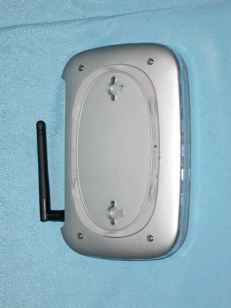
Click to zoom
Application Details
- Equipment Class
- JBP - Part 15 Class B Computing Device Peripheral
- Date of Grant
- Feb 24, 2003
- Application Purpose
- Original Equipment
- Date of Application
- Feb 24, 2003
- Equipment Note
- 54Mbps Wireless Access Point
- Company
- Netgear Incorporated
- Country
- United States
Documents & Files
Document Text
Text extracted from the exhibit documents filed with the FCC. Open a document above to read the original.
Users Manual
Jan./7 th /2003 1 802.11g Wireless LAN Access Point Quick Installation Guide The next-generation wireless LAN device – 802.11g Wireless LAN Access Point is a high- speed wireless unit that performs as a transparent Media Access Control (MAC) bridge between wired Local Area Networks, and wireless networks. The 802.11g Wireless LAN Access Point also provides powerful features such as the Web management, WEP security, and more. Package Content 802.11g Wireless LAN Access Point.......x 1 AC Power Adapter................ .x1 Product CD.....................................x 1 Quick Installation Guide........... x1 NOTE: If any of the above items are missing or damaged, please contact your local dealer for support. Installing the Wireless LAN Access Point Connect the Wireless LAN Access Point to a hub/station with a UTP Ethernet cable. When connecting the Access Point to a PC, please use a cross-over RJ-45 cable. Connect the power adapter to the power socket on the Access Point, and plug the other end of the power pack into an electrical outlet. NOTE: Use ONLY the power adapter supplied with the Wireless LAN Access Point. Otherwise, the product may be damaged. NOTE: The button, labeled “DEFAULT” on the back panel of the Access Point, enables you to retrieve the Access Point’s default setting. This is used when you forget the password. Please detach the DC power plug and press the “DEFAULT” button on the back panel of the Access Point. Reconnect the power and keep holding the button in for a few seconds until the “AP” LED indicator blinks. This will start the Access Point with default settings and enable you to configure the Access Point via utility, telnet or Web again. Jan./7 th /2003 2 Configuring the Wireless LAN Access Point The 802.11g Wireless LAN Access Point allows configuration either via the configuration utility, known as Web Management, or remote access through TCP/IP (Telnet) connection. Web Management The built-in Web Management provides you with a set of user-friendly graphical user interfaces (web pages) to manage your Wireless Access Point. With the assigned IP address (e.g. http://192.168.1.1) to the Access Point, you may get access to the Access Point Web Pages via a web browser (Netscape Navigator 3.0 ~ 4.5 or MS Internet Explorer 4.0 and later) to monitor and configure the Wireless LAN Access Point. 1. Open your web browser. 2. Enter the IP address of your Wireless Smart Station Adapter in the Address field (e.g. http://192.168.1.1). You will have access to the 802.11g Wireless LAN Access Point Web Pages of the Wireless LAN Access Point. 3. Enter the password to login to the Wireless LAN Access Point. The default password is default. The main page will show up. NOTE: The default password to get access to the Access Point is “default”. The Wireless LAN Access Point main page contains five items for you to manage your Wireless LAN Access Point. Jan./7 th /2003 3 ParameterDescription Information Include Access Point’s MAC address, frequency domain and firmware version. Statistics Monitor the Ethernet and wireless network traffic. Configuration Set the Radio mode, IEEE802.11 parameters (ESSID, channel), password, IP address, WEP and Access Control. Upgrade Upgrade the firmware of the Wireless LAN Access Point. Assign Access Point Name: You may assign any name to the Access Point. Assigning the ESSID The ESSID is a unique ID given to the Wireless LAN Access Point. Assign an ESSID to your Access Point (Default value: My Network). The ESSID can be up to 32 characters. Assigning the Channel From Configuration IEEE802.11, select a clear channel for your Wireless LAN Access Point. You may use the Site Survey tool came with the wireless PC Card utility to monitor each channel and choose a channel with good quality. Assigning IP address (optional) Assign an IP address to your Access Point if you wish to configure the Wireless LAN Access Point via the Web Management or Telnet. Consult your network administrator to obtain an available IP address for your Access Point. Using the WEP Encryption (optional) If data transmission with high security is required on your network, it is recommended Jan./7 th /2003 4 that the WEP encryption be used. To activate the WEP encryption, select Configuration, go to the WEP tab, and do the following: ¾ Pull down the WEP Encryption menu and select WEP40 or WEP128. ¾ From the 4 Key entry field, enter the corresponding key value for each encryption method. For WEP40 data encryption: -- 5 alphanumeric characters in the range of “a-z”, “A-Z” and “0-9” (e.g. MyKey). -- 10 digit hexadecimal values in the range of “A-F” , “a-f” and “0-9”, preceded by the characters “0x” values (e.g. 0x11AA22BB33). For WEP128 data encryption: -- 13 alphanumeric characters in the range of “a-z”, “A-Z” and “0-9” (e.g. MyKey12345678). -- 26 digit hexadecimal values in the range of “A-F” , “a-f” and “0-9”, preceded by the characters “0x” values (e.g. 0x00112233445566778899AABBCC). ¾ Enter the 4 WEP keys in the Key 1, Key 2, Key 3 and Key 4 entry filed respectively. Select one WEP key as an active key and click “Apply” to make the setting take effect. NOTE: The WEP key must be set up exactly the same on the Access Point as they are on the wireless client stations. If you set “MyKey” for the Access Point, the same WEP Key “MyKey” must be assigned to other client stations. Jan./7 th /2003 5 Access Point Console The Wireless LAN Access Point can be configured via the command prompt console with Telnet (TCP/IP) connection. z Telnet (TCP/IP) Connection: Assign an IP address to your Wireless LAN Access Point through Access Point Utility and then telnet to the Access Point anywhere to get access to the Access Point console. Then, you will be able to make the configuration via the TCP/IP connection. NOTE: The default password to get access to the Access Point is “default”. For detailed configuration procedures under Telnet, please refer to 802.11g Wireless LAN Access Point User’s …
Text truncated - open the document above for the full version.
External Photos
Company: NETGEAR IncorporatedPage : 1 of 4 Product : 54Mbps Wireless Access PointModel : WG602 Company: NETGEAR IncorporatedPage : 2 of 4 Product : 54Mbps Wireless Access PointModel : WG602 Company: NETGEAR IncorporatedPage : 3 of 4 Product : 54Mbps Wireless Access PointModel : WG602 Company: NETGEAR IncorporatedPage : 4 of 4 Product : 54Mbps Wireless Access PointModel : WG602 Company: NETGEAR IncorporatedPage : 1 of 5 Product : Adapter for the 54Mbps Wireless Access PointModel : DV-151A-1 Company: NETGEAR IncorporatedPage : 2 of 5 Product : Adapter for the 54Mbps Wireless Access PointModel : DV-151A-1 Company: NETGEAR IncorporatedPage : 3 of 5 Product : Adapter for the 54Mbps Wireless Access PointModel : DV-151A-1 Company: NETGEAR IncorporatedPage : 4 of 5 Product : Adapter for the 54Mbps Wireless Access PointModel : DV-151A-1 Company: NETGEAR IncorporatedPage : 5 of 5 Product : Adapter for the 54Mbps Wireless Access PointModel : DV-151A-1
ID Label/Location Info
Company : NETGEAR IncorporatedModel : WG602 Product : 54Mbps Wireless Access Pint 54Mbps Wireless Access Pint Model No: WG602 FCC IDPY3WG602 This device complies with part 15 of the FCC Rules. Operation is subject to the following two conditions: [1] this device may not cause harmful interference and [2] this device must accept any interference received, including interference that may cause undesired operation. S/N Made in Taiwan
ID Label/Location Info
SCALE ECO NO.REVISIONAPP.DES.DATE TOLERANCE GRADE ( ) GRADE ABC LENGTH 60.050.080.20 0.080.100.30 0.100.150.40 0.200.300.80 6618 1850 50180 ~ ~ ~ ~ DRW.DES.CKD.RECKD.APP. MODELSHEET D W G N O . V A 1 1 Z-Com, Inc. NAME PART NO. 1 UNITS GRADEANGLE M.M. TOLERANCE 1 1 N 0 3 A 0 0 6 0 . 1 XG-1000 Netgear WG602 FCC Label 56-060001-82 Kein 920106 : 1.: (Barcode) 2.: 3. 4.: +/- 0.25mm 5.<=0.11mm 6. NPA0049 Tested To Comply With FCC Standards
Internal Photos
Company: NETGEAR IncorporatedPage : 1 of 9 Product : 54Mbps Wireless Access PointModel : WG602 Company: NETGEAR IncorporatedPage : 2 of 9 Product : 54Mbps Wireless Access PointModel : WG602 Company: NETGEAR IncorporatedPage : 3 of 9 Product : 54Mbps Wireless Access PointModel : WG602 Company: NETGEAR IncorporatedPage : 4 of 9 Product : 54Mbps Wireless Access PointModel : WG602 Company: NETGEAR IncorporatedPage : 5 of 9 Product : 54Mbps Wireless Access PointModel : WG602 Company: NETGEAR IncorporatedPage : 6 of 9 Product : 54Mbps Wireless Access PointModel : WG602 Company: NETGEAR IncorporatedPage : 7 of 9 Product : 54Mbps Wireless Access PointModel : WG602 Company: NETGEAR IncorporatedPage : 8 of 9 Product : 54Mbps Wireless Access PointModel : WG602 Company: NETGEAR IncorporatedPage : 9 of 9 Product : 54Mbps Wireless Access PointModel : WG602
Operational Description
WG602 Circuit Description 16. MPU - IDT 79RC32334-150 The IDT RC32334 device is an integrated processor based on theRC32300 CPU core. This product incorporates a high-performance, low-cost 32-bit CPU core with functionality common to a large number of embedded applications. The RC32334 integrates these functions to enable the use of low-cost PC commodity market memory and I/O devices, allowing the aggressive price/performance characteristics of the CPU to be realized quickly into low-cost systems. The RC32334 integrates a SDRAM controller, which provides direct control of system SyncDRAM running at speeds to 75MHz. The local memory and I/O controller implements direct control of external memory devices, including the boot ROM as well as other memory areas, and also implements direct control of external peripherals. In order to leverage the wide availability of low-cost peripherals for the PC market as well as to simplify the design of add-in functions, the RC32334 integrates a full 32-bit PCI bus bridge. 17. Oscillator - Y1 75MHz It’s an oscillator, which can support 75MHz to be IDT 79RC32334’s reference frequency. It’s 3.3V VCC Operation. 18. SDRAM - U3, U5 NT5SV4M16DT The NT5SV4M16DT are four-bank Synchronous DRAMs organized as 1Mbit x 16 I/O x 4 Bank, respectively. These synchronous devices achieve high-speed data transfer rates of up to 200MHz by employing a pipeline chip architecture that synchronizes the output data to a system clock. The chip is fabricated with NTC’s advanced 64Mbit single transistor CMOS DRAM process technology. 19. Flash memory - U2 Intel 28F320J3A, U4 AMD 29LV320T U2 Intel 28F320J3A is High-Density Symmetrically-Blocked Architecture 128-Kbyte Erase Blocks. It’s 2.7V–3.6V VCC Operation. The device organized as 2,097,152 words of 16 bits each or 4,194,304 bytes of 8 bits each. U4 AMD 29LV320T is The Am29LV320D is a 32 megabit, 3.0 volt-only flash memory device, organized as 2,097,152 words of 16 bits each or 4,194,304 bytes of 8 bits each. Word mode data appears on DQ0–DQ15; byte mode data appears on DQ0–DQ7. The device is designed to be programmed in-system with the standard 3.0 volt VCC supply, and can also be programmed in standard EPROM programmers. 20. Reset IC – U8 TPS3823 The TPS3823 supervisor provides circuit initialization and timing supervision. It‘s provided MPU, Flash Memory, Ethernet controller and MINI-PCI reset source. 21. JTAG debug port – J3 The JTAG debug port is option function. It’s provided signal to ICE (In Circuit Emulation) machine at developing. 22. Crystal – Y3 25MHz The crystal provides 25MHz reference frequency source to U12 RTL8139C Ethernet controller. 23. RJ-45 Connector – P1 The RJ-45 connector provides IEEE802.3 standard circuit in physical interface. 24. Magnetic – T1 TS6121C The primary use of transformer (Magnetic) in this type of circuit is as an impedance matching and/or isolation device, serving as a barrier between external cables and internal digital circuitry. 25. Ethernet controller – U12 RTL8139C The Realtek RTL8139C is a highly integrated and cost-effective single-chip Fast Ethernet controller that provides 32-bit performance, PCI bus master capability, and full compliance with IEEE 802.3u 100Base-T specifications and IEEE 802.3x Full Duplex Flow Control. It also supports Advanced Configuration Power management Interface (ACPI), PCI power management for modern operating systems that are capable of Operating System Directed Power Management (OSPM) to achieve the most efficient power management possible. The RTL8139CL is suitable for applications such as CardBus or mobile devices with a built-in network controller. 26. RS-232 Connector port – J3, J4 The RS-232 connector is option function. It’s provided chat debug function at developing. 27. Power supply – U15 MC34063 The MC34063 is a monolithic control circuit containing the primary functions required for DC–to–DC converters. These devices consist of an internal temperature compensated reference, comparator, controlled duty cycle oscillator with an active current limit circuit, driver and high current output switch. This IC was specifically designed to be incorporated in Step–Down and Step–Up and Voltage–Inverting applications with a minimum number of external components. 28. MiniPCI connector – P2 It’s a MiniPCI connector, which can connect 802.11G MiniPCI wireless LAN card. 29. Oscillator – Y3 33MHz It’s an oscillator, which can support 33MHz clock to be all MiniPCI interface reference frequency. It’s 3.3V VCC Operation. 30. Clock buffer – U10 W16-15G The W16-15G Products are five-output zero delay buffers. A Phase-Locked Loop (PLL) is used to take a time-varying signal and provide five copies of that same signal out. The internal feedback to the PLL provides outputs in phase with the reference inputs.
Test Report
FCC ID :PY3WG602 Report No.:510-9201-032F Page 1 of 39 Industrial Technology Research Institute Electronics Research & Service Organization Bldg. 17, 195-4 Sec. 4, Chung Hsing Rd., Chutung,Hsinchu, 310 Taiwan,Republic Of China TEL : 886-3-5917069 FAX : 886-3-5825720 ELECTROMAGNETIC COMPATIBILITY TEST REPORT Company : NETGEAR Incorporated. Address : 4500 Great America Parkway Santa Clara,CA 95054 Product name : 54Mbps Wireless Access Point Model name : WG602 Date Received : DEC. 31, 2002 Date Tested : JAN. 05-15, 2003 MEASUREMENT REQUIREMENT USED : 47 CFR Part 15, Subpart B and Subpart C (Section 15.247), ANSI C63.4-2001 WE HEREBY CERTIFY THAT: The measurements shown in the attachment were made in accordance with the procedures indicated, and the energy emitted by the equipment was found to be within the limits applicable. We assume full responsibility for the accuracy and completeness of these measurements and vouch for the qualifications of all persons taking them. Notes : 1. This report will be invalid if duplicated or photocopied in part. 2. This report refers only to the specimen(s) submitted to test, and is invalid as seperately used. 3. This report is invalid without examination stamp and signature of this institute. 4. The tested specimen(s) will be preserved for thirty days from the data issued. 5. The report must not be used to claim product certification, approval, or endorsement by NVLAP, NIST, or any agency of the federal government. FCC ID :PY3WG602 Report No.:510-9201-032F Page 2 of 39 Industrial Technology Research Institute Electronics Research & Service Organization Bldg. 17, 195-4 Sec. 4, Chung Hsing Rd., Chutung,Hsinchu, 310 Taiwan,Republic Of China TEL : 886-3-5917069 FAX : 886-3-5825720 TABLE OF CONTENTS TITLEPAGE NO. 1. GENERAL INFORMATION.....................................................................................................................4 1.1 GENERAL STATEMENT ..............................................................................................................4 1.2 GENERAL DESCRIPTION OF EUT & POWER ..........................................................................4 1.3 DESCRIPTION OF PERIPHERALS ..............................................................................................5 1.4 EUT & PERIPHERALS SETUP DIAGRAM .................................................................................6 1.5 EUT OPERATING CONDITION ...................................................................................................6 1.6 DESCRIPTION OF TEST SITE .....................................................................................................7 1.7 SUMMARY OF TEST RESULTS ..................................................................................................7 2. CONDUCTED POWERLINE TEST .........................................................................................................8 2.1 TEST EQUIPMENTS......................................................................................................................8 2.2 TEST SETUP...................................................................................................................................8 2.3 CONDUCTED POWER LINE EMISSION LIMIT ........................................................................9 2.4 TEST PROCEDURE .......................................................................................................................9 2.5 UNCERTAINTY OF CONDUCTED EMISSION..........................................................................9 2.6 CONDUCTED RF VOLTAGE MEASUREMENT........................................................................10 2.7 PHOTOS OF CONDUCTION TEST ..............................................................................................11 3. RADIATED EMISSION TEST .................................................................................................................12 3.1 TEST EQUIPMENTS......................................................................................................................12 3.2 TEST SETUP...................................................................................................................................12 3.3 RADIATION LIMIT .......................................................................................................................13 3.4 TEST PROCEDURES .....................................................................................................................14 3.5 UNCERTAINTY OF RADIATED EMISSION..............................................................................14 3.6 RADIATED RF NOISE MEASUREMENT ...................................................................................15-23 3.7 PHOTOS OF OPEN SITE ...............................................................................................................24-25 4. 6dB BANDWIDTH MEASUREMENT ....................................................................................................26 4.1 TEST EQUIPMENTS......................................................................................................................26 4.2 TEST SETUP...................................................................................................................................26 4.3 LIMITS OF 6dB BANDWIDTH MEASUREMENT .....................................................................26 4.4 TEST PROCEDURE .......................................................................................................................26 4.5 UNCERTAINTY OF CONDUCTED EMISSION..........................................................................26 4.6 TEST RESULTS .............................................................................................................................27 4.7 PHOTO OF 6DB BANDWIDTH MEASURERMENT ..................................................................28 5. MAXIMUM PEAK OUTPUT POWER .................…
Text truncated - open the document above for the full version.
Test Setup Photos
FCC ID :PY3WG602 Report No.:510-9201-032F Page 1 of 3 Industrial Technology Research Institute Electronics Research & Service Organization Bldg. 17, 195-4 Sec. 4, Chung Hsing Rd., Chutung,Hsinchu, 310 Taiwan,Republic Of China TEL : 886-3-5917069 FAX : 886-3-5825720 2.7 PHOTOS OF CONDUCTION TEST FCC ID :PY3WG602 Report No.:510-9201-032F Page 2 of 3 Industrial Technology Research Institute Electronics Research & Service Organization Bldg. 17, 195-4 Sec. 4, Chung Hsing Rd., Chutung,Hsinchu, 310 Taiwan,Republic Of China TEL : 886-3-5917069 FAX : 886-3-5825720 3.7 PHOTOS OF OPEN SITE FCC ID :PY3WG602 Report No.:510-9201-032F Page 3 of 3 Industrial Technology Research Institute Electronics Research & Service Organization Bldg. 17, 195-4 Sec. 4, Chung Hsing Rd., Chutung,Hsinchu, 310 Taiwan,Republic Of China TEL : 886-3-5917069 FAX : 886-3-5825720 3.7 PHOTOS OF OPEN SITE
Contact Information
Applicant
David Kay
Test Firm
Compliance Certification Services Inc.Paul Liau
Technical Specifications
| # | Rule Parts | Frequency Range | Power Output |
|---|---|---|---|
| 1 | 15B | - | - |
Other Applications from Netgear Incorporated

PY325100647
Aug 04, 2026BE5000 Dual-Band PoE 2.5G Insight Managed WiFi 7 Outdoor Access Point
Equipment Class
DTS - Digital Transmission SystemPY325300652
May 12, 2026BE5000 Dual-Band PoE 2.5G Insight Managed WiFi 7 Access Point
Equipment Class
NII - Unlicensed National Information Infrastructure TXPY325400656
Apr 16, 2026Orbi Outdoor Satellite
Equipment Class
DTS - Digital Transmission SystemPY324400640
Dec 12, 2025Orbi 11BE WiFi 7 Tri-band Router, Orbi 11BE WiFi 7 Tri-band Satellite
Equipment Class
NII - Unlicensed National Information Infrastructure TXPY324100618
Jul 31, 2024Nighthawk 5G Mobile Router
Equipment Class
PCB - PCS Licensed Transmitter