PY3WG602V454 Mbps Wireless Access Point
Netgear Incorporated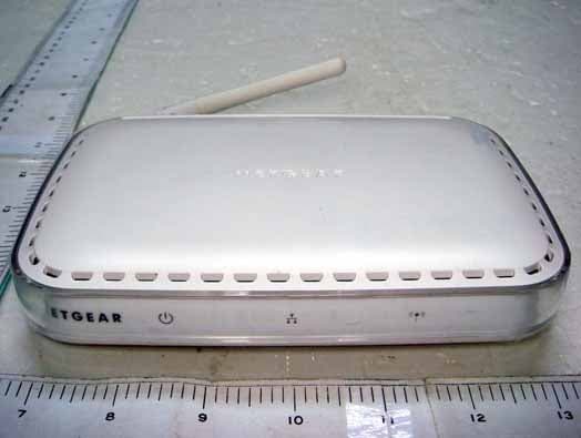
Click to zoom
Application Details
- Equipment Class
- DTS - Digital Transmission System
- Date of Grant
- May 03, 2007
- Application Purpose
- Original Equipment
- Date of Application
- May 03, 2007
- Equipment Note
- 54 Mbps Wireless Access Point
- Frequency Range
- 2412.00000000 - 2462.00000000
- Company
- Netgear Incorporated
- Country
- United States
Documents & Files
Document Text
Text extracted from the exhibit documents filed with the FCC. Open a document above to read the original.
Users Manual
)NSTALLATION'UIDE NETGEAR WG602v4 54 Mbps Wireless Access Point Start Here Please refer to the Reference Manual on your Resource CD for instructions on advanced configuration options. Estimated Completion Time: 30 minutes. Tip: Before mounting the WG602v4 in a high location, first set up and test the WG602v4 to verify wireless network connectivity. First, Set Up the WG602v4 1. Connect the wireless access point to your computer and modem a.Unpack the box and verify the contents. b.Prepare a PC with an Ethernet adapter. If this PC is already part of your network, record its TCP/IP configuration settings. Configure the PC with a static IP address of 192.168.0.210 and 255.255.255.0 as the Subnet Mask. c.Connect an Ethernet cable from the WG602v4 to the PC (point A in the illustration). d.Securely insert the other end of the cable into the WG602v4 Ethernet port (point B in the illustration). 4 Ethernet Port Blue NETGEAR Cable WG602v4 Computer A B e.Turn on your computer, connect the power adapter to the WG602v4 and verify the following: • The power light should be lit. If the power light is not lit, check the connections and check to see if the power outlet is controlled by a wall switch that is turned off. • The LAN light on the WG602v4 should be lit (amber for a 10 Mbps connection and green for a 100 Mbps connection). If not, make sure the Ethernet cable is securely attached at both ends. • The WLAN light should be lit. 2. Configure LAN and Wireless Access a.Configure the WG602v4 Ethernet port for LAN access. •Connect to the WG602v4 by opening your browser and entering http://192.168.0.227 in the address field. •When prompted, enter admin for the user name and password for the password, both in lower case letters. •Click the Basic Settings link and configure the IP Settings for your network. b.Configure the wireless interface for wireless access. See the online help or the Reference Manual for full instructions. c.Test wireless connectivity using a PC with a wireless adapter configured according to the wireless settings you just set in the WG602v4 to establish a wireless connection to the WG602v4. Now that you have finished the setup steps, you are ready to deploy the WG602v4 in your network. If needed, you can now reconfigure the PC you used in step 1 back to its original TCP/IP settings. 227 Deploy the WG602v4 1.Disconnect the WG602v4 and position it where you will deploy it. The best location is elevated, such as wall mounted or on the top of a cubicle, at the center of your wireless coverage area, and within line of sight of all the mobile devices. 2.Position the antenna. Vertical positioning provides best side-to-side coverage. Horizontal positioning provides best top-to-bottom coverage. 3.Connect an Ethernet cable from your WG602v4 Access Point to a LAN port on your router, switch, or hub. 4.Connect the power adapter to the wireless access point and plug the power adapter in to a power outlet. The PWR, LAN, and WLAN lights should light up. Tip: The WG602v4 supports Power Over Ethernet (PoE). If you have a switch that provides PoE, you will not need to use the power adapter to power the WG602v4. This can be especially convenient when the WG602v4 is installed in a high location far away from a power outlet. Now, Verify Wireless Connectivity Using a computer with an 802.11g or 802.11b wireless adapter, verify connectivity by using a browser such as Netscape® or Internet Explorer to connect to the Internet, or check for file and printer access on your network. Note: If you cannot connect, see to Troubleshooting Tips in this guide or the Reference Manual on the Resource CD for the ProSafe Wireless Access Point. February 2005 Troubleshooting Tips Here are some tips for correcting simple problems you may have. No lights are lit on the access point. The access point has no power. •Make sure the power cord is connected to the access point and plugged in to a working power outlet or power strip. •Make sure you are using the correct NETGEAR power adapter supplied with your access point. The Ethernet light is not lit. There is a hardware connection problem. •Make sure the cable connectors are securely plugged in at the access point and the network device (hub, switch, or router). •Make sure the connected device is turned on. The WLAN light is not lit. The access point’s antennas are not working. •If the Wireless LAN activity light stays off, disconnect the adapter from its power source and then plug it in again. •Make sure the antennas are tightly connected to the WG602v4. •Contact NETGEAR if the WLAN light remains off. I cannot configure the access point from a browser. Check these items: •The WG602v4 is properly installed, LAN connections are OK, and it is powered on. Check that the LAN port LED is green to verify that the Ethernet connection is OK. •If you are using the NetBIOS name of the WG602v4 to connect, ensure that your PC and the WG602v4 are on the same network segment or that there is a WINS server on your network. •If your PC uses a Fixed (Static) IP address, ensure that it is using an IP Address in the range of the WG602v4. The WG602v4 default IP Address is 192.168.0.227 and the default Subnet Mask is 255.255.255.0. The WG602v4 default setting is for a static IP address. If the network where you are connecting it is using DHCP, configure it accordingly. See the Reference Manual on the Resource CD for the ProSafe Wireless Access Point for more details. I cannot access the Internet or the LAN with a wireless capable computer. There is a configuration problem. Check these items: •You may not have restarted the computer with the wireless adapter to have TCP/IP changes take effect. Restart the computer. •The computer with the wireless adapter may not have the correct TCP/IP settings to communicate with the network. Restart the computer and check that TCP/IP is set up properly for that network. The usual setting for Windows on the Network Properties is set to “Obtain an IP address automat…
Text truncated - open the document above for the full version.
Block Diagram
55 44 33 22 11 D D C C B B A A 1ADFS-020018 Rev: 00 10/100WANPHY Ethernet MAC/MII Flash ROM 2M Bytes 3.3V LEDCircuit 1.8V UART Tx Path 802.11gMAC/BB/RADIO USB 2.0 SDRAM8MBytes TX/RXSwitch 240MHz MIPS32 Core MMU Omit BCM5354 25MHzCrystal 3.3V PowerAmplifier POWERCONSUMPTION 10/100LANPHY RJ45 forLAN SE2528L ANT1ANT2 Filter Adapter : 7.5V@1A (7.5W) (350mA@maximum) Magnetic Balun Balun Balun Rx Path 1.2V (TBD@Current) TBD 1ADSS-xxxxxx 1.0 BLOCK DIAGRAM C Friday, April 13, 2007 DELTA NETWORKS, INC. 9 2 TitleSize Document Number Rev Date: Sheet of
Cover Letter(s)
Request for non-disclosure RF_501_02 Netgear Inc. 4500 Great America Parkway Santa Clara, CA 95054 USA To: Telefication B.V. Attn: Dept. FCC TCB Edisonstraat 12A 6902 PK ZEVENAAR The Netherlands Subject: Request for non-disclosure (FCC ID:PY3WG602V4)Please fill Reference number: WG602 v4 Date: 2007/3/13 Dear FCC TCB, Persuant to 47 CFR Section 0.459(a) & (b), Netgear Inc. hereby requests non-disclosure and confidential treatment of the following materials submitted in support of FCC certification application for FCC ID: ( PY3WG602V4) a. Schematic diagrams b. Operational description Above materials contain secrets, proprietary and technical information, which would customarily be quarded from competitors under 47 CFR, section 0.457(d)(2). Disclosure or publication or any portion of this company confidential material to other parties could cause substantial competitive harm and provide unjustified benefits for competitors. Netgear Inc. understands that pursuant to 47 CFR section 0.457(d)(1)(ii) disclosure of the applicant and all accompanying documentation will not be made before the date of the grant. Mark Gandler
Cover Letter(s)
RF_160, Issue 01 Declaration of Authorization We Name: Netgear Inc. Address: 4500 Great America Parkway City: Santa Clara, CA 95054 Country: USA Declare that: Name: Exclusive Certification Corporation Address: 4F-2, No.28 Lang 78, Xing-Ai Rd. City: Nei-hu Taipei City 114 Country Taiwan, R.O.C. is authorized to apply for Certification of the following product(s): Product Description: 802.11 b/g AP Model: WG602 v4 Brand: Netgear on our behalf. Date: 2007/3/13 City: California Name: Mark Gandler Signature:
External Photos
Exclusive Certification Corp. Tel:886-2-2792-3366 Fax:886-2-2792-1100 Issued date: Apr. 12, 2007 1 of 6 FCC Test Report: FI07012603-A Appendix A. Photographs of EUT 07012603-A 07012603-A
ID Label/Location Info
SHEET: AUTHOR:TITLE: P/N: REV: THIS DOCUMENT AND THE DATA DISCLOSED HEREIN OR WHEREWITH IS NOT TO BE REPRODUCED, USED OR DISCLOSED IN WHOLE OR IN PART TO ANYONE WITHOUT THE PERMISSION OF NETGEAR, INC. REVDESCRIPTION OF REVISIONENG APPDDATE NOTE: 1. REFER TO NETGEAR SPEC. DOC-00093 FOR COLOR TOLERANCES. 2. INK COLOR IS SHOWN TO THE RIGHT. 3. DIE LINES ARE MAGENTA COLOR AND DO NOT PRINT. 4. MAC & SERIAL NUMBERS TO BE PRINTED BY THE ODM. 5. INSURE COUNTRY OF ORIGIN IS CORRECT. A. IF COUNTRY OF ORIGIN IS PRE-PRINTED, UNHIDE THE APPROPRIATE COUNTRY OF ORIGIN LAYER AND INCLUDE COUNTRY OF ORIGIN ON LABEL. B. IF COUNTRY OF ORIGIN IS POST-PRINTED USING A THERMAL PRINTER (OR EQUIVALENT), OMIT TEXT FROM ARTWORK (USE LAYERS). 5 01AW-10283-011 of 1 AW, WG602, V4H1, PLBLJ RAMONES 07FEB07J RAMONESINITIAL DOCUMENT CREATION01 Pantone 430C WG602 V4H1 Product Label Scale is 1:1 Die line is magenta, do not print Designed by NETGEAR in California FCC ID: PY3WG602V4IC: 4054A-WG602V4 NGR-WG602 0984 N10947 272-10487-01 MAC SERIAL http://192.168.0.227 DEFAULT ACCESS user name: admin password: password WirelessEthernetPower LAN: GREEN =100Mbps / YELLOW =10MbpsBLINK = ACTIVITY Ethernet Restore Factory Settings 7.5V1A 54 Mbps Wireless Access Point WG602 v4
Internal Photos
Exclusive Certification Corp. Tel:886-2-2792-3366 Fax:886-2-2792-1100 Issued date: Apr. 12, 2007 2 of 6 FCC Test Report: FI07012603-A 07012603-A 07012603-A Exclusive Certification Corp. Tel:886-2-2792-3366 Fax:886-2-2792-1100 Issued date: Apr. 12, 2007 3 of 6 FCC Test Report: FI07012603-A 07012603-A 07012603-A Exclusive Certification Corp. Tel:886-2-2792-3366 Fax:886-2-2792-1100 Issued date: Apr. 12, 2007 4 of 6 FCC Test Report: FI07012603-A 07012603-A 07012603-A Exclusive Certification Corp. Tel:886-2-2792-3366 Fax:886-2-2792-1100 Issued date: Apr. 12, 2007 5 of 6 FCC Test Report: FI07012603-A 07012603-A Exclusive Certification Corp. Tel:886-2-2792-3366 Fax:886-2-2792-1100 Issued date: Apr. 12, 2007 6 of 6 FCC Test Report: FI07012603-A 07012603-A 07012603-A
RF Exposure Info
1.1. Test Result of RF Exposure Evaluation . Product: 54 Mbps Wireless Access Point . Test Item: RF Exposure Evaluation Data . Test site: OATSI-SD . Test Mode: Normal Operation 1.1.1. Antenna Gain The maximum Gain is 2.0 dBi. 1.1.2. EUT Operation condition Software provided by client enabled the EUT to transmit and receive data at lowest, middle and highest channel individually. 1.1.3. Output Power into Antenna & RF Exposure Evaluation Distance 20 cm Modulation Standard: IEEE 802.11b Test Date: Feb. 28, 2007 Temperature: 23 Humidity: 69 Channel Channel Frequency (MHz) Output Power to Antenna (dBm) Power Density (S) (mW/cm 2 ) 01 2412 18.48 0.022 06 2437 18.42 0.022 11 2462 18.38 0.022 Modulation Standard: IEEE 802.11g Test Date: Feb. 28, 2007 Temperature: 23 Humidity: 69 Channel Channel Frequency (MHz) Output Power to Antenna (dBm) Power Density (S) (mW/cm 2 ) 01 2412 16.44 0.014 06 2437 16.37 0.014 11 2462 16.16 0.013 The MPE is calculated as 0.022 mW / cm 2 < limit 1 mW / cm 2 . So, RF exposure limit warning or SAR test are not required. For 2412-2462 MHz, the EUT will only be used with a separation of 20cm or greater between the antenna and nearby persons and can therefore be considered a mobile transmitter per 47CFR2.1091 (b). The RF Exposure Information page from the manual is included here for reference.
Test Report
Exclusive Certification Corp. Tel:886-2-2792-3366 Fax:886-2-2792-1100 Issued date: Apr. 12, 2007 1 of 56 FCC Test Report: FI07012603-A FCC TEST REPORT according to FCC Rules and Regulations Part 15 Subpart C Applicant : Netgear lnc. Address : 4500 Great America Parkway, Santa Clara, California 95054 U.S.A. Equipment : 54 Mbps Wireless Access Point Model No. : WG602 v4 FCC ID : PY3WG602V4 Trade Name : Netgear Laboratory Accreditation 1332 The test result refers exclusively to the test presented test model / sample., Without written approval of Exclusive Certification Corp. the test report shall not be reproduced except in full. The EUT is also considered as a kind of computer peripheral, because the connection to computer is necessary for typical use. It has been verified to comply with the requirements of FCC Part 15, Subpart B, Class B (DoC). The test report has been issued separately. Exclusive Certification Corp. Tel:886-2-2792-3366 Fax:886-2-2792-1100 Issued date: Apr. 12, 2007 2 of 56 FCC Test Report: FI07012603-A Contents 1. Report of Measurements and Examinations .................................................................................... 5 1.1 List of Measurements and Examinations ................................................................................... 5 2. Test Configuration of Equipment under Test ................................................................................... 6 2.1 Feature of Equipment under Test............................................................................................... 6 2.2 RF Specifications ....................................................................................................................... 6 2.3 Test Mode and Test Software..................................................................................................... 7 2.4 Description of Test System......................................................................................................... 7 2.5 Connection Diagram of Test System..........................................................................................8 2.6 General Information of Test........................................................................................................ 9 2.7 History of this test report ............................................................................................................ 9 3. Antenna Requirements.....................................................................................................................10 3.1 Standard Applicable ................................................................................................................. 11 3.2 Antenna Construction and Directional Gain............................................................................. 11 4. Test of Conducted Emission............................................................................................................12 4.1 Test Limit..................................................................................................................................12 4.2 Test Procedures.......................................................................................................................12 4.3 Typical Test Setup ...................................................................................................................13 4.4 Measurement equipment .........................................................................................................13 4.5 Test Result and Data................................................................................................................14 4.6 Test Photographs .....................................................................................................................17 5. Test of Radiated Emission ...............................................................................................................18 5.1 Test Limit..................................................................................................................................18 5.2 Test Procedures.......................................................................................................................19 5.3 Typical Test Setup ....................................................................................................................20 5.4 Measurement equipment .........................................................................................................20 5.5 Test Result and Data................................................................................................................21 5.6 Test Photographs .....................................................................................................................37 6. 6dB Bandwidth Measurement Data .................................................................................................38 6.1 Test Limit ..................................................................................................................................38 6.2 Test Procedures .......................................................................................................................38 6.3 Test Setup Layout ....................................................................................................................38 6.4 Measurement equipment .........................................................................................................38 6.5 Test Result and Data................................................................................................................38 7. Maximum Peak Output Power .........................................................................................................42 7.1 Test Limit ..................................................................................................................................42 7.2 Test Procedures .............................................................................…
Text truncated - open the document above for the full version.
Test Setup Photos
Exclusive Certification Corp. Tel:886-2-2792-3366 Fax:886-2-2792-1100 Issued date: Apr. 12, 2007 17 of 56 FCC Test Report: FI07012603-A 4.6 Test Photographs Front View Rear View Exclusive Certification Corp. Tel:886-2-2792-3366 Fax:886-2-2792-1100 Issued date: Apr. 12, 2007 37 of 56 FCC Test Report: FI07012603-A 5.6 Test Photographs Front View Rear View
Contact Information
Applicant
David Kay
Technical Contact
Netgear Inc.Mark Gandler
[email protected]+1 408 907 8000
4500 Great America Parkway · Santa Clara, California · United States
Test Firm
Cerpass Technology CorporationAnson Chou
Technical Specifications
| # | Rule Parts | Frequency Range | Power Output |
|---|---|---|---|
| 1 | 15C | 2.41 GHz - 2.46 GHz | 70.00 mW |
Other Applications from Netgear Incorporated

PY325100647
Aug 04, 2026BE5000 Dual-Band PoE 2.5G Insight Managed WiFi 7 Outdoor Access Point
Equipment Class
DTS - Digital Transmission SystemPY325300652
May 12, 2026BE5000 Dual-Band PoE 2.5G Insight Managed WiFi 7 Access Point
Equipment Class
NII - Unlicensed National Information Infrastructure TXPY325400656
Apr 16, 2026Orbi Outdoor Satellite
Equipment Class
DTS - Digital Transmission SystemPY324400640
Dec 12, 2025Orbi 11BE WiFi 7 Tri-band Router, Orbi 11BE WiFi 7 Tri-band Satellite
Equipment Class
NII - Unlicensed National Information Infrastructure TXPY324100618
Jul 31, 2024Nighthawk 5G Mobile Router
Equipment Class
PCB - PCS Licensed Transmitter