PY3WGR614V454Mbps Wireless Router
Netgear Incorporated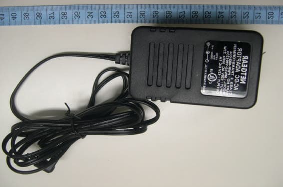
Click to zoom
Application Details
- Equipment Class
- DTS - Digital Transmission System
- Date of Grant
- Feb 02, 2004
- Application Purpose
- Original Equipment
- Date of Application
- Feb 02, 2004
- Equipment Note
- 54Mbps Wireless Router
- Frequency Range
- 2412.00000000 - 2462.00000000
- Company
- Netgear Incorporated
- Country
- United States
Documents & Files
Document Text
Text extracted from the exhibit documents filed with the FCC. Open a document above to read the original.
Users Manual
SM-WGR614NA-1 Version 1.0 March 2003 NETGEAR, Inc. 4500 Great America Parkway Santa Clara, CA 95054 USA Reference Manual for the Model WGR614 Cable/DSL Wireless Router Notice : The changes or modifications not expressly approved by the party responsible for compliance could void the user's authority to operate the equipment. THIS DEVICE COMPLIES WITH PART 15 OF THE FCCRULES. OPERATIONS IS SUBJECT TO THE FOLLOWING TWO CONDITIONS: ( 1 ) THIS DEVICE MAY NOT CAUSE HARMFUL INTERFERENCE AND ( 2 ) THIS DEVICE MUST ACCEPT ANY INTERFERENCE RECEIVED, INCLUDING INTERFERENCE THAT . MAY CAUSE UNDESIRED OPERATION ii © 2003 by NETGEAR, Inc. All rights reserved. Trademarks NETGEAR is a trademark of Netgear, Inc. Microsoft, Windows, and Windows NT are registered trademarks of Microsoft Corporation. Other brand and product names are registered trademarks or trademarks of their respective holders. Statement of Conditions In the interest of improving internal design, operational function, and/or reliability, NETGEAR reserves the right to make changes to the products described in this document without notice. NETGEAR does not assume any liability that may occur due to the use or application of the product(s) or circuit layout(s) described herein. Federal Communications Commission (FCC) Compliance Notice: Radio Frequency Notice This equipment has been tested and found to comply with the limits for a Class B digital device, pursuant to part 15 of the FCC Rules. These limits are designed to provide reasonable protection against harmful interference in a residential installation. This equipment generates, uses, and can radiate radio frequency energy and, if not installed and used in accordance with the instructions, may cause harmful interference to radio communications. However, there is no guarantee that interference will not occur in a particular installation. If this equipment does cause harmful interference to radio or television reception, which can be determined by turning the equipment off and on, the user is encouraged to try to correct the interference by one or more of the following measures: •Reorient or relocate the receiving antenna. •Increase the separation between the equipment and receiver. •Connect the equipment into an outlet on a circuit different from that to which the receiver is connected. •Consult the dealer or an experienced radio/TV technician for help. EN 55 022 Declaration of Conformance This is to certify that the Model WGR614 Cable/DSL Wireless Router is shielded against the generation of radio interference in accordance with the application of Council Directive 89/336/EEC, Article 4a. Conformity is declared by the application of EN 55 022 Class B (CISPR 22). iii Bestätigung des Herstellers/Importeurs Es wird hiermit bestätigt, daß das Model WGR614 Cable/DSL Wireless Router gemäß der im BMPT-AmtsblVfg 243/ 1991 und Vfg 46/1992 aufgeführten Bestimmungen entstört ist. Das vorschriftsmäßige Betreiben einiger Geräte (z.B. Testsender) kann jedoch gewissen Beschränkungen unterliegen. Lesen Sie dazu bitte die Anmerkungen in der Betriebsanleitung. Das Bundesamt für Zulassungen in der Telekommunikation wurde davon unterrichtet, daß dieses Gerät auf den Markt gebracht wurde und es ist berechtigt, die Serie auf die Erfüllung der Vorschriften hin zu überprüfen. Certificate of the Manufacturer/Importer It is hereby certified that the Model WGR614 Cable/DSL Wireless Router has been suppressed in accordance with the conditions set out in the BMPT-AmtsblVfg 243/1991 and Vfg 46/1992. The operation of some equipment (for example, test transmitters) in accordance with the regulations may, however, be subject to certain restrictions. Please refer to the notes in the operating instructions. Federal Office for Telecommunications Approvals has been notified of the placing of this equipment on the market and has been granted the right to test the series for compliance with the regulations. Compliance with the applicable regulations is dependent upon the use of shielded cables. It is the responsibility of the user to procure the appropriate cables. Voluntary Control Council for Interference (VCCI) Statement This equipment is in the second category (information equipment to be used in a residential area or an adjacent area thereto) and conforms to the standards set by the Voluntary Control Council for Interference by Data Processing Equipment and Electronic Office Machines aimed at preventing radio interference in such residential areas. When used near a radio or TV receiver, it may become the cause of radio interference. Read instructions for correct handling. Customer Support Refer to the Support Information Card that shipped with your Model WGR614 Cable/DSL Wireless Router. World Wide Web NETGEAR maintains a World Wide Web home page that you can access at the universal resource locator (URL) http://www.netgear.com. A direct connection to the Internet and a Web browser such as Internet Explorer or Netscape are required. iv This page intentionally left blank. Contentsv Contents Preface About This Manual Chapter 1 Introduction Key Features of the Router ............................................................................................1-1 802.11g Wireless Networking ...................................................................................1-2 A Powerful, True Firewall with Content Filtering ......................................................1-2 Security ....................................................................................................................1-3 Autosensing Ethernet Connections with Auto Uplink™ ...........................................1-3 Extensive Protocol Support ......................................................................................1-3 Easy Installation and Management ..........................................................................1-4 Maintenance and Support ..........................................................................…
Text truncated - open the document above for the full version.
Cover Letter(s)
1 Chris Harvey From:S. S. Liou [[email protected]] Sent:Tuesday, February 03, 2004 1:39 AM To:Chris Harvey Subject:Re: Additional information needed for AN04T3575 FCC ID: PY3WGR614V4 Exhibit-D-ID_Label_ revised.pdf... Dear Chris, The revised FCC ID label is attached. Best regards, ================================ S. S. Liou Engineer / EMC Dep. II ETC ----- Original Message ----- From: "Chris Harvey" <[email protected]> To: "'S. S. Liou'" <[email protected]>; "Chris Harvey" <[email protected]> Cc: "R00/???" <[email protected]> Sent: Tuesday, February 03, 2004 8:06 AM Subject: RE: Additional information needed for AN04T3575 FCC ID: PY3WGR614V4 > Dear S. S. Liou, Thank you for providing all the information you have sent. > Everything submitted so far has been reviewed and meets the FACC > requirements. I am still waiting on a revised FCC ID Label per my original > request at the bottom of this e-mail. > > Please contact me if there are any questions. > > Best regards, > > Chris Harvey > > > -----Original Message----- > From: S. S. Liou [mailto:[email protected]] > Sent: Monday, February 02, 2004 4:41 AM > To: Chris Harvey > Cc: R00/??? > Subject: Re: Additional information needed for AN04T3575 FCC ID: PY3WGR614V4 > > Dear Chris, > > For your questions, > > Ans. #1: Please refer to attached external photos file 2 > "Exhibit-H-External_Photos.pdf". Ans. #2: Please refer to revised > block diagram and test report page 29. Ans. #3: Please refer to > revised authorization letter and Confidentiality Letter. Test report > doesn't need to be changed because the capital letter 'V' is used. > > Best regards, > > ================================ > S. S. Liou > Engineer / EMC Dep. II > ETC > > ----- Original Message ----- > From: "Chris Harvey" <[email protected]> > To: <[email protected]> > Cc: "Mike Kuo" <[email protected]> > Sent: Monday, January 19, 2004 9:37 AM > Subject: FW: Additional information needed for AN04T3575 FCC ID: PY3WGR614V4 > > > > Will, > > The application for NetGear has been reviewed and the following > > items need > > to be addressed. > > > > The exhibit submitted for the External Photographs of the EUT would > > not > open > > (file error). Please re-send a correct copy of this external > > photograph exhibit. (this is a repeat of an earlier e-mail today) > > > > The Block Diagram and Test Report state that this device uses > > standard sma > > connectors. This is not allowed in accordance with FCC 15.203. > > Please correct this and state how the device complies with FCC > > 15.203. > > > > The FCC ID Label has 2 errors. The " FCC ID: PY3WGR614 v4 " is not > allowed > > per FCC requirements because there are not allowed to be s[paces or lower > > case letters. One way of correcting this would be to use 'FCC ID: > > PY3WGR614V4' as is stated in the Test Report. The exhibits for the > > Confidentiality Letter and Agent Authorization also need to correct > > the > use > > of the lower case 'v'. Please correct and resubmit these 3 > > exhibits. > > > > The items indicated above must be submitted before processing can continue > > on the above referenced application. Failure to provide the > > requested information within 30 days of the original e-mail date may > > result in application dismissal and forfeiture of the filing fee. > > Also, please 3 note > > that partial responses increase processing time and should not be > submitted. > > Any questions about the content of this correspondence should be directed > to > > the e-mail address listed below the name of the sender. > > > > Please respond directly to [email protected] (reply to this e-mail). > > > > Best regards, > > > > Chris Harvey
External Photos
ETC Report No. : ET92R-11-068-03 FCC ID.:PY3WGR614V4 Rev. No 1.0 CONSTRUCTED PHOTOS of EUT Front View of EUT Bottom View of EUT ETC Report No. : ET92R-11-068-03 FCC ID.:PY3WGR614V4 Rev. No 1.0 CONSTRUCTED PHOTOS of EUT Side View of EUT Side View of EUT ETC Report No. : ET92R-11-068-03 FCC ID.:PY3WGR614V4 Rev. No 1.0 CONSTRUCTED PHOTOS of EUT Top View of EUT Rear View of EUT ETC Report No. : ET92R-11-068-03 FCC ID.:PY3WGR614V4 Rev. No 1.0 CONSTRUCTED PHOTOS of EUT Front View of Adaptor Rear View of Adaptor
Internal Photos
ETC Report No. : ET92R-11-068-03 FCC ID.:PY3WGR614v4 Rev. No 1.0 CONSTRUCTED PHOTOS of EUT Internal View of EUT ETC Report No. : ET92R-11-068-03 FCC ID.:PY3WGR614v4 Rev. No 1.0 CONSTRUCTED PHOTOS of EUT Component View of Main PCB Component View of Main PCB ETC Report No. : ET92R-11-068-03 FCC ID.:PY3WGR614v4 Rev. No 1.0 CONSTRUCTED PHOTOS of EUT Solder View of Main PCB ETC Report No. : ET92R-11-068-03 FCC ID.:PY3WGR614v4 Rev. No 1.0 CONSTRUCTED PHOTOS of EUT Internal View of Adaptor Component View of Adaptor ETC Report No. : ET92R-11-068-03 FCC ID.:PY3WGR614v4 Rev. No 1.0 CONSTRUCTED PHOTOS of EUT Solder View of Adaptor
Operational Description
WGR614V2 Operation Principle 1. CPU, U6, 88W8510 have a 32-bit RISC processor integrated, operation frequency is 160MHz. It needs an external 44MHz crystal for reference frequency; this crystal is also used for RF module. This chip is responsible to control RF-Baseband Transceiver (88W8000G), Flash IC and LED. This chip also has MII interface integrated to communicate with 10/100 Ethernet Switch. 2. FLASH, U13, AM29LV800BT-70EC, 8Mbits Flash, bottom sector, 70ns. It is used to store the normal and test firmware. 3. Integrated 2.4GHz ISM Band RF-Baseband Transceiver, U9, 88W8000G which is integrated all RF-Baseband receive and Transmit function. On-Chip Power Amplifier (PA) with up to +20 dBm output power at the antenna port. It is also integrated programmable frequency synthesizers with integrated VCOs, I/Q generation and CMOS up/down conversion mixers. 4. 10/100 Ethernet Switch, U10, 88E6060 support automatic MDI/MDIX crossover for 100BASE-TX and 10 BASE-T ports. Port 5 has dedicated, always on, MAC Mode (Forward) and PHY Mode (Reverse) RMII/MII/SNI interface for management and firewall applications. Each port works at 10Mbps or 100Mbp, full-duplex or half-duplex mode (forced or auto-negotiated). Flexible LED support for Link, Speed, Duplex Mode, Collision, and TX/RX Activities. 5. Power part: there are several regulators are used on the board. U17, AZ1084S-3 is used to transfer DC12V to DC3V3; U1, U8 AME8805 are used to transfer DC3V3 to DC2V5; U20, 1117-ADJ is used to transfer DC3V3 to DC1V62. The core of CPU is operate at 1.5V. 6. LED part: LED Color Controlled by Description Amber (Test) FW On - Error condition. Off - Normal operation Blinking - This LED blinks during start up/ Upgrade F/W Power/Test (Double color LED) Green (Power) F/W (TI CPU use H/W) On – System booting complete and then turn it on Amber (10) HW On - Link at 10Mbps Blinking – receiving/ transmitting data LAN (Double color LED) Green (100) HW On - Link at 100Mbps Blinking – receiving/ transmitting data Amber (10) HW On - Link at 10Mbps Blinking – receiving/ transmitting data Internet (Double color LED) Green (100) HW On - Link at 100Mbps Blinking – receiving/ transmitting data WLAN Green FW On - Wireless connection available; Wireless Access Point is ready for use. Off - No Wireless connection available. Blinking - Data is transmitted or received via the Wireless access point. This includes "network traffic" as well as user data. 7. Switch button, SW1, it is used to reset the 88W8510. 8.
Test Report
Rev. No 2.0 FCC Part 15 EMI TEST REPORT of E.U.T. : 54Mbps Wireless Router FCC ID. : PY3WGR614V4 MODEL : WGR614v4 for APPLICANT : NETGEAR Inc. ADDRESS : 4500 Great America Parkwar, Santa Clara, CA 95054, U.S.A. Test Performed by ELECTRONICS TESTING CENTER, TAIWAN NO. 34, LIN 5, DING FU TSUN, LINKOU HSIANG TAIPEI HSIEN, TAIWAN, R.O.C. Tel : (02)26023052 Fax : (02)26010910 http://www.etc.org.tw ; e-mail: [email protected] Report Number : ET92R-11-068-03 ETC Report No. : ET92R-11-068-03 FCC ID.: PY3WGR614V4 Rev. No 1.0 TEST REPORT CERTIFICATION Applicant : NETGEAR Inc. 4500 Great America Parkwar, Santa Clara, CA 95054, U.S.A. Manufacturer : NETGEAR Inc. 4500 Great America Parkwar, Santa Clara, CA 95054, U.S.A. Description of EUT : a) Type of EUT : 54Mbps Wireless Router b) Trade Name : NETGEAR c) Model No. : WGR614v4 d) Power Supply : Adapter(Model:MW48-1200800) I/P: 120Vac/60Hz 22W; O/P: 12Vdc, 800mA Regulation Applied : FCC Rules and Regulations Part 15 Subpart B & C (2002) I HEREBY CERTIFY THAT: The data shown in this report were made in accordance with the procedures given in ANSI C63.4, and the energy emitted by the device was founded to be within the limits applicable. I assume full responsibility for accuracy and completeness of these data. Note: 1. The result of the testing report relate only to the item tested. 2. The testing report shall not be reproduced expect in full, without the written approval of ETC. Issued Date : Dec. 22, 2003 Test Engineer : ( Kevin Lee ) Approve & Authorized Signer : Will Yauo, Manager EMC Dept. II of ELECTRONICS TESTING CENTER, TAIWAN ETC Report No. : ET92R-11-068-03 FCC ID.: PY3WGR614V4 Rev. No 1.0 Table of Contents Page 1 GENERAL INFORMATION.......................................................................................................1 1.1 Product Description........................................................................................................................1 1.2 Characteristics of Device................................................................................................................1 1.3 Test Methodology..........................................................................................................................1 1.4 Test Facility....................................................................................................................................1 2 PROVISIONS APPLICABLE.......................................................................................................2 2.1 Definition........................................................................................................................................2 2.2 Requirement for Compliance...........................................................................................................3 2.3 Restricted Bands of Operation........................................................................................................5 2.4 Labeling Requirement.....................................................................................................................5 2.5 User Information............................................................................................................................6 3. SYSTEM TEST CONFIGURATION...........................................................................................7 3.1 Justification.....................................................................................................................................7 3.2 Devices for Tested System.............................................................................................................7 4 RADIATED EMISSION MEASUREMENT..............................................................................8 4.1 Applicable Standard.......................................................................................................................8 4.2 Measurement Procedure.................................................................................................................8 4.3 Measuring Instrument...................................................................................................................10 4.4 Radiated Emission Data................................................................................................................11 4.4.1 RF Portion...............................................................................................................................11 4.4.2 Radiated Eimssion of Restricted bands......................................................................................17 4.4.3 Other Emission........................................................................................................................19 4.5 Field Strength Calculation.............................................................................................................20 4.6 Photos of Radiation Measuring Setup............................................................................................21 5 CONDUCTED EMISSION MEASUREMENT........................................................................22 5.1 Standard Applicable.....................................................................................................................22 5.2 Measurement Procedure...............................................................................................................22 5.3 Conducted Emission Data.............................................................................................................23 5.4 Result Data Calculation.................................................................................................................26 5.5 Conducted Measurement Equipment.............................................................................................27 5.6 Photos of Conduction Measuring Setup........................................................................................28 6 ANTENNA REQUIREMENT................…
Text truncated - open the document above for the full version.
Test Report
ETC Report No. : ET92R-11-068-03Sheet 28 of 52Sheets FCC ID.: PY3WGR614V4 Rev. No 2.0 Appendix 4 : Ploted Datas of Band Edge Emission ETC Report No. : ET92R-11-068-03Sheet 29 of 52Sheets FCC ID.: PY3WGR614V4 Rev. No 2.0 802.11b ETC Report No. : ET92R-11-068-03Sheet 30 of 52Sheets FCC ID.: PY3WGR614V4 Rev. No 2.0 ETC Report No. : ET92R-11-068-03Sheet 31 of 52Sheets FCC ID.: PY3WGR614V4 Rev. No 2.0 802.11g ETC Report No. : ET92R-11-068-03Sheet 32 of 52Sheets FCC ID.: PY3WGR614V4 Rev. No 2.0 ETC Report No. : ET92R-11-068-03Sheet 33 of 52Sheets FCC ID.: PY3WGR614V4 Rev. No 2.0 Appendix 5 : Ploted Datas of Power Density ETC Report No. : ET92R-11-068-03Sheet 34 of 52Sheets FCC ID.: PY3WGR614V4 Rev. No 2.0 802.11b ETC Report No. : ET92R-11-068-03Sheet 35 of 52Sheets FCC ID.: PY3WGR614V4 Rev. No 2.0 ETC Report No. : ET92R-11-068-03Sheet 36 of 52Sheets FCC ID.: PY3WGR614V4 Rev. No 2.0 ETC Report No. : ET92R-11-068-03Sheet 37 of 52Sheets FCC ID.: PY3WGR614V4 Rev. No 2.0 802.11g ETC Report No. : ET92R-11-068-03Sheet 38 of 52Sheets FCC ID.: PY3WGR614V4 Rev. No 2.0 ETC Report No. : ET92R-11-068-03Sheet 39 of 52Sheets FCC ID.: PY3WGR614V4 Rev. No 2.0 ETC Report No. : ET92R-11-068-03Sheet 40 of 52Sheets FCC ID.: PY3WGR614V4 Rev. No 2.0 Appendix 6 : Plotted Data for Out-of-Band Conducted Emission ETC Report No. : ET92R-11-068-03Sheet 41 of 52Sheets FCC ID.: PY3WGR614V4 Rev. No 2.0 802.11b ETC Report No. : ET92R-11-068-03Sheet 42 of 52Sheets FCC ID.: PY3WGR614V4 Rev. No 2.0 ETC Report No. : ET92R-11-068-03Sheet 43 of 52Sheets FCC ID.: PY3WGR614V4 Rev. No 2.0 ETC Report No. : ET92R-11-068-03Sheet 44 of 52Sheets FCC ID.: PY3WGR614V4 Rev. No 2.0 ETC Report No. : ET92R-11-068-03Sheet 45 of 52Sheets FCC ID.: PY3WGR614V4 Rev. No 2.0 ETC Report No. : ET92R-11-068-03Sheet 46 of 52Sheets FCC ID.: PY3WGR614V4 Rev. No 2.0 ETC Report No. : ET92R-11-068-03Sheet 47 of 52Sheets FCC ID.: PY3WGR614V4 Rev. No 2.0 802.11g ETC Report No. : ET92R-11-068-03Sheet 48 of 52Sheets FCC ID.: PY3WGR614V4 Rev. No 2.0 ETC Report No. : ET92R-11-068-03Sheet 49 of 52Sheets FCC ID.: PY3WGR614V4 Rev. No 2.0 ETC Report No. : ET92R-11-068-03Sheet 50 of 52Sheets FCC ID.: PY3WGR614V4 Rev. No 2.0 ETC Report No. : ET92R-11-068-03Sheet 51 of 52Sheets FCC ID.: PY3WGR614V4 Rev. No 2.0 ETC Report No. : ET92R-11-068-03Sheet 52 of 52Sheets FCC ID.: PY3WGR614V4 Rev. No 2.0
Test Report
ETC Report No. : ET92R-11-068-03 Sheet 29 of 40Sheets FCC ID.: PY3WGR614V4 Rev. No 2.0 6 ANTENNA REQUIREMENT 6.1 Standard Applicable For intentional device, according to 15.203, an intentional radiator shall be designed to ensure that no antenna other than that furnished by the responsible party shall be used with the device. And according to 15.247 (b), if transmitting antennas of directional gain greater than 6 dBi are used, the power shall be reduced by the amount in dB that the directional gain of the antenna exceeds 6 dBi. 6.2 Antenna Construction and Directional Gain An integrated 2.0dBi gain dipole antenna . Please see constraction Photos Of Exhibit B for details.
Test Setup Photos
ETC Report No. : ET92R-11-068-03 FCC ID.: PY3WGR614V4 Rev. No 2.0 Photos of Radiation Measuring Setup ETC Report No. : ET92R-11-068-03 FCC ID.: PY3WGR614V4 Rev. No 2.0 Photos of Conduction Measuring Setup
Contact Information
Applicant
David Kay
Test Firm
Electronics Testing Center, TaiwanWin-Po Tsai
Technical Specifications
| # | Rule Parts | Frequency Range | Power Output |
|---|---|---|---|
| 1 | 15C | 2.41 GHz - 2.46 GHz | 38.00 mW |
Other Applications from Netgear Incorporated

PY325100647
Aug 04, 2026BE5000 Dual-Band PoE 2.5G Insight Managed WiFi 7 Outdoor Access Point
Equipment Class
DTS - Digital Transmission SystemPY325300652
May 12, 2026BE5000 Dual-Band PoE 2.5G Insight Managed WiFi 7 Access Point
Equipment Class
NII - Unlicensed National Information Infrastructure TXPY325400656
Apr 16, 2026Orbi Outdoor Satellite
Equipment Class
DTS - Digital Transmission SystemPY324400640
Dec 12, 2025Orbi 11BE WiFi 7 Tri-band Router, Orbi 11BE WiFi 7 Tri-band Satellite
Equipment Class
NII - Unlicensed National Information Infrastructure TXPY324100618
Jul 31, 2024Nighthawk 5G Mobile Router
Equipment Class
PCB - PCS Licensed Transmitter