PYFAR400USFHSS RFID Reader
Symbol Technologies, Inc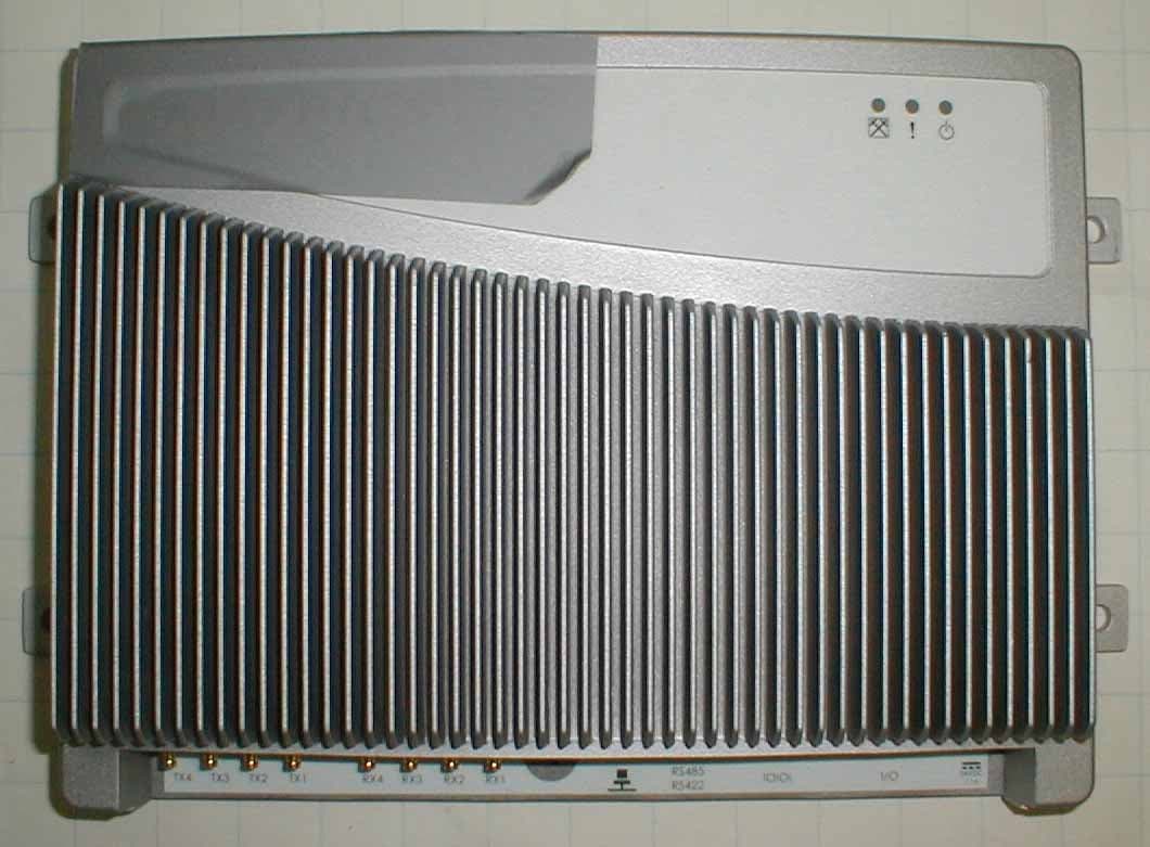
Click to zoom
Application Details
- Equipment Class
- DSS - Part 15 Spread Spectrum Transmitter
- Date of Grant
- Jul 20, 2004
- Application Purpose
- Original Equipment
- Date of Application
- Jul 20, 2004
- Equipment Note
- FHSS RFID Reader
- Frequency Range
- 902.70000000 - 927.22000000
- Company
- Symbol Technologies, Inc
- Country
- United States
Documents & Files
Document Text
Text extracted from the exhibit documents filed with the FCC. Open a document above to read the original.
Users Manual
AR 400 Reader User’s Manual Published: June 21, 2004 Part Number: 110003-001 Matrics, Inc. 7361 Calhoun Place Suite 250 Rockville, MD 20855 Tel: 301.610.6100 Fax: 301.610.6101 http://www.matrics.com ii AR 400 Reader User’s Manual 2003-2004 Matrics, Inc. Notices Copyright 2003-2004 Matrics, Inc. All rights reserved. This document is protected by copyright with all rights reserved. No part of the document may be reproduced or transmitted by any means or in any form without prior consent in writing from Matrics, Inc. Trademarks Matrics is a registered trademark of Matrics, Inc. All other product names or logos mentioned herein are used for identification purposes only, and are the trademarks of their respective owners. Statement of Rights IMPORTANT – READ CAREFULLY: Matrics products incorporate technology that is protected by U.S. patent and other intellectual property (IP) rights owned by Matrics, Inc, and other rights owners. Use of these products constitutes your legal agreement to honor Matrics’ IP rights as protected by applicable laws. Reverse engineering, decompiling, or disassembly of Matrics products is strictly prohibited. Violators will be prosecuted. AR 400 Reader User’s Manual 2003-2004 Matrics, Inc. iii Contents SECTION 1. INTRODUCTION............................................................................................. 1 Document Conventions.............................................................................................. 1 Acronyms and Abbreviations ..................................................................................... 1 References ................................................................................................................. 1 Disclaimer ................................................................................................................. 1 S ECTION 2. SYSTEM DESCRIPTION.................................................................................. 2 Product Description................................................................................................... 2 S ECTION 3. SPECIFICATIONS AND DIAGRAMS.................................................................. 3 AR-400-US Reader Specification............................................................................... 3 AR-400-US Reader Diagrams.................................................................................... 4 Top View ................................................................................................................................... 4 Side View.................................................................................................................................. 4 LEDs and Connectors................................................................................................ 5 Interface Pin-Outs...................................................................................................... 5 I/O Interface ............................................................................................................................. 5 Ethernet Interface .................................................................................................................... 6 RS422/485 Interface................................................................................................................ 6 RS232 Interface........................................................................................................................ 7 Power Supply............................................................................................................................ 7 PCMCIA Interface.................................................................................................................... 8 S ECTION 4. INSTALLING THE READER............................................................................. 9 Getting Started .......................................................................................................... 9 Mount the Reader .................................................................................................... 10 Connect Antenna(s) to the Reader ........................................................................... 11 Connect the Reader to a Host Computer.................................................................. 11 Power On (and Off) the Reader ............................................................................... 11 Verify the Reader Installation................................................................................... 12 Reader On?............................................................................................................................. 12 Test Read Range..................................................................................................................... 12 S ECTION 5. CONFIGURING THE READER....................................................................... 13 Launch and Log In to the Reader Administrator Console ......................................... 13 Use Setup Wizard.................................................................................................... 15 Use Online Help ...................................................................................................... 16 Save or Discard Changes (or Revert to Backup)......................................................17 Create Read Point Classes ....................................................................................... 18 Create Read Point Zones ......................................................................................... 21 Configure the Reader ............................................................................................... 23 Modify a Reader’s Attributes................................................................................................ 24 Add, Modify, or Delete Read Points...........................................................................…
Text truncated - open the document above for the full version.
Users Manual
AR 400 Reader User’s Manual Published: June 21, 2004 Part Number: 110003-001 Matrics, Inc. 7361 Calhoun Place Suite 250 Rockville, MD 20855 Tel: 301.610.6100 Fax: 301.610.6101 http://www.matrics.com ii AR 400 Reader User’s Manual 2003-2004 Matrics, Inc. Notices Copyright 2003-2004 Matrics, Inc. All rights reserved. This document is protected by copyright with all rights reserved. No part of the document may be reproduced or transmitted by any means or in any form without prior consent in writing from Matrics, Inc. Trademarks Matrics is a registered trademark of Matrics, Inc. All other product names or logos mentioned herein are used for identification purposes only, and are the trademarks of their respective owners. Statement of Rights IMPORTANT – READ CAREFULLY: Matrics products incorporate technology that is protected by U.S. patent and other intellectual property (IP) rights owned by Matrics, Inc, and other rights owners. Use of these products constitutes your legal agreement to honor Matrics’ IP rights as protected by applicable laws. Reverse engineering, decompiling, or disassembly of Matrics products is strictly prohibited. Violators will be prosecuted. AR 400 Reader User’s Manual 2003-2004 Matrics, Inc. iii Contents SECTION 1. INTRODUCTION............................................................................................. 1 Document Conventions.............................................................................................. 1 Acronyms and Abbreviations ..................................................................................... 1 References ................................................................................................................. 1 Disclaimer ................................................................................................................. 1 S ECTION 2. SYSTEM DESCRIPTION.................................................................................. 2 Product Description................................................................................................... 2 S ECTION 3. SPECIFICATIONS AND DIAGRAMS.................................................................. 3 AR-400-US Reader Specification............................................................................... 3 AR-400-US Reader Diagrams.................................................................................... 4 Top View ................................................................................................................................... 4 Side View.................................................................................................................................. 4 LEDs and Connectors................................................................................................ 5 Interface Pin-Outs...................................................................................................... 5 I/O Interface ............................................................................................................................. 5 Ethernet Interface .................................................................................................................... 6 RS422/485 Interface................................................................................................................ 6 RS232 Interface........................................................................................................................ 7 Power Supply............................................................................................................................ 7 PCMCIA Interface.................................................................................................................... 8 S ECTION 4. INSTALLING THE READER............................................................................. 9 Getting Started .......................................................................................................... 9 Mount the Reader .................................................................................................... 10 Connect Antenna(s) to the Reader ........................................................................... 11 Connect the Reader to a Host Computer.................................................................. 11 Power On (and Off) the Reader ............................................................................... 11 Verify the Reader Installation................................................................................... 12 Reader On?............................................................................................................................. 12 Test Read Range..................................................................................................................... 12 S ECTION 5. CONFIGURING THE READER....................................................................... 13 Launch and Log In to the Reader Administrator Console ......................................... 13 Use Setup Wizard.................................................................................................... 15 Use Online Help ...................................................................................................... 16 Save or Discard Changes (or Revert to Backup)......................................................17 Create Read Point Classes ....................................................................................... 18 Create Read Point Zones ......................................................................................... 21 Configure the Reader ............................................................................................... 23 Modify a Reader’s Attributes................................................................................................ 24 Add, Modify, or Delete Read Points...........................................................................…
Text truncated - open the document above for the full version.
Cover Letter(s)
Version 1.12 Matrics Confidential Material 25 March 2002 May 25, 2004 American Telecommunications Certification Body, Inc. 6731 Whittier Avenue Suite C110 McLean, VA 22101 To Whom It May Concern: Please be advised that Matrics Technology Inc. authorizes Washington Laboratories, Ltd. to act on our behalf, until otherwise notified, for applications submitted to American Telecommunications Certification Body, Inc. (ATCB). We certify that we are not subject to denial of federal benefits that includes FCC benefits, pursuant to Section 5301 of the Anti-Drug Abuse ACT of 1988, U.S.C. 862. Further, no party, as defined in 47 CFR 1.2002(b), to the application is subject to denial of federal benefits, that includes FCC benefits. Thank you for your attention to this matter. Matt Truong Test Engineer Matrics Technology Inc.
Cover Letter(s)
Version 1.12 Matrics Confidential Material 25 March 2002 July 9, 2004 American Telecommunications Certification Body, Inc. 6731 Whittier Avenue Suite C110 McLean, VA 22101 RE: Certification Application FCC ID: PYFAR400US Please be advised that the following exhibits are to be held confidential on behalf of Matrics Technology Inc.: - Schematics - Theory of Operation - Block Diagrams - Parts Lists - Frequency Hopping Information The application contains technical information that Matrics Technology Inc. deems to be trade secrets and proprietary. If made public, the information might be used to the disadvantage of the applicant in the market place. Thank you for your attention to this matter. Matt Truong Test Engineer Matrics Technology Inc.
Cover Letter(s)
Response to FCC Comments FCC ID: PYFAR400US 1 Washington Laboratories, Ltd. 7560 LINDBERGH DRIVE GAITHERSBURG, MD 20879 (301) 417 – 0220 FAX # (301) 417 - 9069 September 9, 2004 Mr. William Graff - American Telecommunications Certification Body Inc. Mr. Mike Nicolay - FCC Equipment Authorization Branch CORRESPONDENCE 13779, dated 9/08/04 APPLICATION: PYFAR400US Matrics, Inc. 731 Confirmation Number: TC817139 Gentlemen: Below are the comments that have been provided regarding the application for certification referenced above. Our responses to those comments are in bold italic. Many responses refer you to additional exhibit(s) which has been uploaded to the application folder at the ATCB website. Thank you for your attention. Please feel free to contact us for any additional information that you may require. Regards, Gregory M. Snyder Chief EMC Engineer, Wireless/Telco Services Manager Brian J. Dettling Documentation Specialist WLL Project: 8096 1. Are you planning on addressing the RT's I've sent? We will have to flag your future applications if no response is received. R. Responses to Correspondence Numbers 13555 and 13667 have been prepared and submitted.
Cover Letter(s)
Response to FCC Comments FCC ID: PYFAR400US 1 Washington Laboratories, Ltd. 7560 LINDBERGH DRIVE GAITHERSBURG, MD 20879 (301) 417 – 0220 FAX # (301) 417 - 9069 September 9, 2004 Mr. William Graff - American Telecommunications Certification Body Inc. Mr. Mike Nicolay - FCC Equipment Authorization Branch CORRESPONDENCE 13667, dated 8/31/04 APPLICATION: PYFAR400US Matrics, Inc. 731 Confirmation Number: TC817139 Gentlemen: Below are the comments that have been provided regarding the application for certification referenced above. Our responses to those comments are in bold italic. Many responses refer you to additional exhibit(s) which has been uploaded to the application folder at the ATCB website. Thank you for your attention. Please feel free to contact us for any additional information that you may require. Regards, Gregory M. Snyder Chief EMC Engineer, Wireless/Telco Services Manager Brian J. Dettling Documentation Specialist WLL Project: 8096 1. Please explain if the transmitter is transmitting CW signals, I could find no spectrum plots and the operational description doesn't seem to indicate what type of modulation is being used, if any. We have consistently denied proposals for RF tag readers that transmit a CW signal to a passive tag under the Frequency hopping rules in Section 15.247. For these systems, the transmit bandwidth (cw signal) does not match the receiver bandwidth as required by Section 15.247(a)1. Also the definition of a Frequency hopping system in Section 2.1 requires that the carrier of a frequency hopping system be modulated with coded information. A device using CW signals to read passive tags and applying under the FHSS rules in Section 15.247 would not meet these requirements. R. The transmitter is not transmitting CW signals. The modulation used is AM (ASK) as shown in Section 3.1 of the AR400US Operational Description. Additionally, the modulation can be seen in the Occupied Bandwidth plots in the test report Figures 4-8, 4-9, and 4-10.
Cover Letter(s)
Response to FCC Comments FCC ID: PYFAR400US 1 Washington Laboratories, Ltd. 7560 LINDBERGH DRIVE GAITHERSBURG, MD 20879 (301) 417 – 0220 FAX # (301) 417 - 9069 September 9, 2004 Mr. William Graff - American Telecommunications Certification Body Inc. Mr. Mike Nicolay - FCC Equipment Authorization Branch CORRESPONDENCE 13555, dated 8/19/04 APPLICATION: PYFAR400US Matrics, Inc. 731 Confirmation Number: TC817139 Gentlemen: Below are the comments that have been provided regarding the application for certification referenced above. Our responses to those comments are in bold italic. Many responses refer you to additional exhibit(s) which has been uploaded to the application folder at the ATCB website. Thank you for your attention. Please feel free to contact us for any additional information that you may require. Regards, Gregory M. Snyder Chief EMC Engineer, Wireless/Telco Services Manager Brian J. Dettling Documentation Specialist WLL Project: 8096 1.The User's Manual states that they use a commercially available rf connector. Are they aren't using a unique connector? R. The manual incorrectly identifies the connector as a mini-UHF connector. The connector used (DIN 1.0/2.3) is unique and is a special order item for Matrics. These connectors are not commercially available nor are they sold at any retail stores. Photographs of the connector have been uploaded for further clarification. Please see exhibit “Antenna Connector Detail.pdf”. The manual has also been updated to remove the reference of “Mini-UHF”. Response to FCC Comments FCC ID: PYFAR400US 2 2. RFx exhibit contains phrases: "Maximum Permissible Exposure Test Report," "RF Exposure Test Report," etc. -however this exhibit contains only MPE calculations but no test results. In this and future filings, please replace word "Test" with "Evaluation" or similar. R. The RF Exposure exhibit has been revised to remove the reference as a “Test Report” and replaced with “Evaluation”. Please see exhibit “AR400US RF Exposure Info rev1.pdf”. 3. Part 15 intentional radiators are approved with specific antennas - please submit descriptions and/or internal and external photos or drawings of specific antenna(s) authorized for this device. R. The specification and datasheet of the antenna which is part of the FCC testing has been provided. Please see exhibit “Area antenna spec DS1.pdf”. 4. Please submit block diagram and/or operational info, including power division conditions if any, related to user manual statement: "Up to four (4) individually addressable antennas (read points), reducing cost per read point", or specify exact location in filing if info is already there. R. No power division of the RF takes place. Each antenna is independently selected and only one is selected at any time as can be seen in the “Antenna interface control block diagram” on page 30 of the Operational Description. 5. User manual states "Mini-UHF Antenna Connectors" - please explain how device complies with 15.203 and 15.204. R. Reference Item 1 above. The connectors are unique and not commercially available. 6. User manual has 23cm antenna spacing on one page, and 25cm spacing on another - please clarify and/or revise R. The User Manual has been corrected to show a 23cm spacing. Please see exhibit “AR400US Users Manual revised.pdf”. 7. User manual states - "This device must be installed in a location that is not accessible to the general public." Please describe typical installation locations. R. These units are installed in large warehouse applications for inventory tracking. Installation includes large volume storage areas and large doorways for moving inventory through. Typical installations to date include asset tracking within a warehouse for International Paper and a baggage tracking system for McCarran Airport. 8. Test setup photos seem to show only one panel antenna. Please explain how these results apply for the 4-antenna configuration, and/or re-test if needed. R. All Tx and Rx ports do not work simultaneously. Only one antenna can be selected at any time.
External Photos
Top View Bottom View Front View Side View Back View
External Photos
Antenna Connector Detail
External Photos
High-Performance Area Antenna HIGHLIGHTS: Mount around doorways and dock doors for high throughput tracking High-Performance Antenna Arrays Matrics general purpose antennas (Model: ANT-GP-HP) are fully packaged, high performance, rectangular antenna arrays: ` 28.25” long x ` 12.5” wide x ` 1.5” thick. They meet standard technical requirements necessary to start any RFID project, and come ready for implementation with Matrics’ Readers – Stationary Reader SR-400 and Advanced Reader AR-400. The Antenna for High- Capacity, High Throughput Environments Matrics general purpose antennas are intended for long range and large area Matrics RFID tag reading. Optimized to perform in a variety of industrial and retail environments, they can easily be mounted indoors on ceilings and walls to create read zones around shelves, doorways and dock doors. Matrics general purpose antennas are solid state devices that contain no moving parts or mechanical switches. After installation, there is no configuration necessary to become operational. ` Wide Read Field ` High Speed RF Signal Conversion Matrics High-Performance Antenna’s for Increased pallet Visibility High-Performance Area Antenna ` ASIAN OPERATIONS: ` 11 Orchard Turn #06-08 ` Singapore 238800 ` (65) 6839.1193 ` MATRICS, INC ` 7361 CALHOUN PLACE, SUITE 250 ` ROCKVILLE, MD 20855 ` 301.601.6100 © 2004 Matrics, Inc. All rights reserved. Matrics is a registered trademark of Matrics, Inc. All other trademarks and logos are the property of their respective owners Technical Specifications Characteristic Description Name/Model & Part Number General Purpose Antenna (Model: ANT-GP- HP; PN: 250012-001) Type Two circular polarized patch array Dimensions 28.25” long x 12.5” wide x 1.5” thick Weight Approximately 8 pounds Casing Aluminum with PVC plastic cover Temperature Operating: 0º to +50º C (+32º to +122º F) Storage: -20º to +70º C (-4º to +158º F) Connectors Two (2) type “N” female connectors Voltage Standing Wave Ratio (VSWR) 1.25 Isolation -db -37 3db Beam Width 60º Gain in dbd/linear 6.75 Highlights ` Wide Read Field ` High Speed RF Signal Conversion
ID Label/Location Info
Product Label Label Location
Internal Photos
Cover Removed Board A Top Board A Bottom Board B Top Board B Bottom
RF Exposure Info
Document 8096-MPE, Rev. 0 FCC ID: PYFAR400US RF Exposure Test Report Washington Laboratories, Ltd June 2004 Maximum Permissible Exposure Test Report for Matrics, Inc. RFID Device FCC ID: PYFAR400US June 16, 2004 WLL PROJECT #: 8096X This report may not be reproduced, except in full, without the prior written consent of Washington Laboratories, Ltd. RF Exposure Test Report Document 8096-MPE, Rev. 0 FCC ID: PYFAR400US RF Exposure Test Report Washington Laboratories, Ltd June 2004 1 Maximum Permissible Exposure Test Report for FCC ID: PYFAR400US 1.0 Introduction This report has been prepared on behalf of Matrics, Inc. FHSS RFID Device to show compliance with the RF exposure requirements as defined in FCC §1.1307. 1.1 Requirements Three different categories of transmitters are defined by the FCC in OET Bulletin 65. These categories are fixed installation, mobile, and portable and are defined as follows: Fixed Installations: fixed location means that the device, including its antenna, is physically secured at a permanent location and is not able to be easily moved to another location. Additionally, distance to humans from the antenna is maintained to at least 2 meters. Mobile Devices: a mobile device is defined as a transmitting device designed to be used in other than fixed locations and to be generally used in such a way that a separation distance of at least 20 centimeters is normally maintained between the transmitter's radiating structures and the body of the user or nearby persons. Transmitters designed to be used by consumers or workers that can be easily re-located, such as a wireless modem operating in a laptop computer, are considered mobile devices if they meet the 20 centimeter separation requirement. The FCC rules for evaluating mobile devices for RF compliance are found in 47 CFR §2.1091. Portable Devices: a portable device is defined as a transmitting device designed to be used so that the radiating structure(s) of the device is/are within 20 centimeters of the body of the user. Portable device requirements are found in Section 2.1093 of the FCC's Rules (47 CFR§2.1093). For this test report the Matrics RFID device with 6dBi antenna is considered a fixed installation as it is used for the purpose of reading tags. The FCC also categorizes the use of the device as based upon the user’s awareness and ability to exercise control over his or her exposure. The two categories defined are Occupational/ Controlled Exposure and General Population/Uncontrolled Exposure. These two categories are defined as follows: Document 8096-MPE, Rev. 0 FCC ID: PYFAR400US RF Exposure Test Report Washington Laboratories, Ltd June 2004 2 Occupational/Controlled Exposure: In general, occupational/controlled exposure limits are applicable to situations in which persons are exposed as a consequence of their employment, who have been made fully aware of the potential for exposure and can exercise control over their exposure. This exposure category is also applicable when the exposure is of a transient nature due to incidental passage through a location where the exposure levels may be higher than the general population/uncontrolled limits, but the exposed person is fully aware of the potential for exposure and can exercise control over his or her exposure by leaving the area or by some other appropriate means. Awareness of the potential for RF exposure in a workplace or similar environment can be provided through specific training as part of a RF safety program. If appropriate, warning signs and labels can also be used to establish such awareness by providing prominent information on the risk of potential exposure and instructions on methods to minimize such exposure risks. General Population/Uncontrolled Exposure: The general population / uncontrolled exposure limits are applicable to situations in which the general public may be exposed or in which persons who are exposed as a consequence of their employment may not be made fully aware of the potential for exposure or cannot exercise control over their exposure. Members of the general public would come under this category when exposure is not employment-related; for example, in the case of a wireless transmitter that exposes persons in its vicinity. Warning labels placed on low-power consumer devices such as cellular telephones are not considered sufficient to allow the device to be considered under the occupational/controlled category, and the general population/uncontrolled exposure limits apply to these devices. Since there are no warnings or training associated with this unit and it can be used by anyone, the Matrics RFID device is evaluated to the General Population/Uncontrolled Exposure limits. 1.2 Radio Frequency Radiation Exposure Evaluation The highest RF output power of the unit was measured at 30dBm at 915 MHz. According to §1.1310 of the FCC rules, the power density limit for General Population/Uncontrolled Exposure at 915 MHz is 0.610mW/cm 2 . The MPE is calculated to show the required separation distance that must be maintained during installation to maintain compliance with the power density limit. The following formula was used to calculate the Power Density: 2 4R PG S π = Where: S = Power Density P = Output Power at the Antenna Terminals G = Gain of Transmit Antenna (linear gain) R = Distance from Transmitting Antenna To solve for the minimum mounting distance required: Document 8096-MPE, Rev. 0 FCC ID: PYFAR400US RF Exposure Test Report Washington Laboratories, Ltd June 2004 3 S PG R π4 = For this device, the calculation is as follows: S = 0.610 mW/cm 2 P = Output Power = 1000 mW G = Worst Case Gain = 6dBi = INVLOG(6/10) = 4 61.04 )4()1000( ×× × = π R = 23 cm (Based on continuous transmission) Based on the above calculation the Matrics AR 400 Reader antenna must be mounted such that it provides a minimum separation distance of 23 cm. The User’s Manual addresses the mounting location in the instructions for mounting the reader.
RF Exposure Info
Document 8096-MPE, Rev. 1 FCC ID: PYFAR400US RF Exposure Evaluation Washington Laboratories, Ltd September 2004 Maximum Permissible Exposure Evaluation for Matrics, Inc. RFID Device FCC ID: PYFAR400US June 16, 2004 WLL PROJECT #: 8096X This report may not be reproduced, except in full, without the prior written consent of Washington Laboratories, Ltd. RF Exposure Evaluation Document 8096-MPE, Rev. 1 FCC ID: PYFAR400US RF Exposure Test Evaluation Washington Laboratories, Ltd September 2004 1 Maximum Permissible Exposure Evaluation for FCC ID: PYFAR400US 1.0 Introduction This report has been prepared on behalf of Matrics, Inc. FHSS RFID Device to show compliance with the RF exposure requirements as defined in FCC §1.1307. 1.1 Requirements Three different categories of transmitters are defined by the FCC in OET Bulletin 65. These categories are fixed installation, mobile, and portable and are defined as fo…
Text truncated - open the document above for the full version.
Contact Information
Applicant
Qianlin Zhou(Regulatory Specialist)
Technical Contact
Washington Laboratories, Ltd.Gregory Snyder
[email protected]301-417-0220
7560 Lindbergh Drive · Gaithersburg, Maryland · United States
Test Firm
Washington Laboratories, Ltd.Steven Koster
Technical Specifications
| # | Rule Parts | Frequency Range | Power Output |
|---|---|---|---|
| 1 | 15C | 902.7 MHz - 927.22 MHz | 1 W |
Other Applications from Symbol Technologies, Inc
PYFRDRRUG100
Oct 13, 2003Ruggedized RFID Reader
Equipment Class
LMS - Part 90 Location & Monitoring Transmitter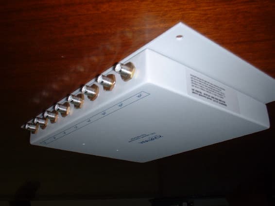
PYFRDR090
Feb 18, 2003Tag Reader
Equipment Class
TNB - Licensed Non-Broadcast Station Transmitter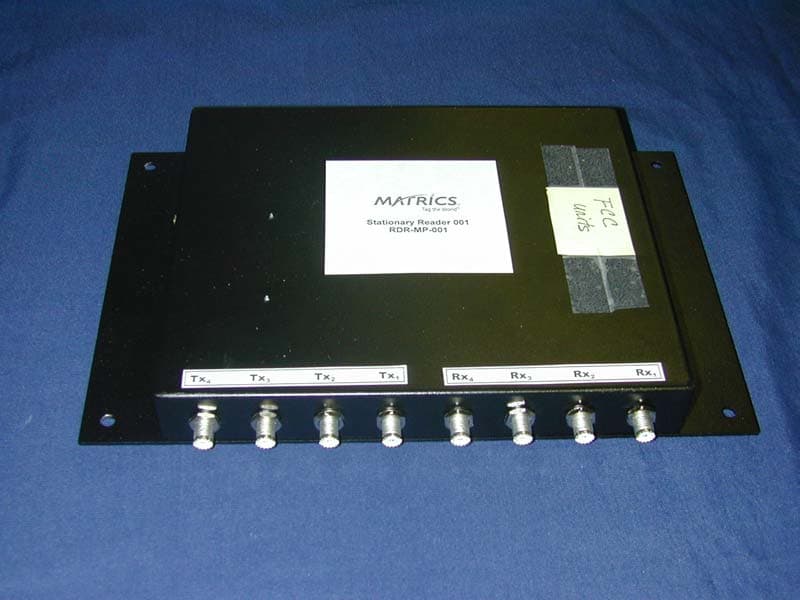
PYFRDRMP001
Feb 19, 2002Frequency Hopping Spread Spectrum Transmitter
Equipment Class
DSS - Part 15 Spread Spectrum Transmitter