PYFRDRRUG100Ruggedized RFID Reader
Symbol Technologies, Inc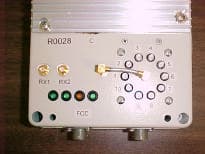
Click to zoom
Application Details
- Equipment Class
- LMS - Part 90 Location & Monitoring Transmitter
- Date of Grant
- Oct 13, 2003
- Application Purpose
- Original Equipment
- Date of Application
- Oct 13, 2003
- Equipment Note
- Ruggedized RFID Reader
- Frequency Range
- 909.75000000 - 921.75000000
- Company
- Symbol Technologies, Inc
- Country
- United States
Documents & Files
Document Text
Text extracted from the exhibit documents filed with the FCC. Open a document above to read the original.
Users Manual
Ruggedized Reader User’s Manual Revised: October 6, 2003 Document Control Number: MNI03H001 Matrics, Inc. 8850 Stanford Boulevard Suite 3000 Columbia, MD 21045 Tel: 410.872.0300 Fax: 410.872.0700 http://www.matrics.com Notices Copyright 2003 Matrics, Inc. All rights reserved. This document is protected by copyright with all rights reserved. No part of the document may be reproduced or transmitted by any means or in any form without prior consent in writing from Matrics, Inc. Trademarks Matrics is a registered trademark of Matrics, Inc. All other product names or logos mentioned herein are used for identification purposes only, and are the trademarks of their respective owners. Statement of Rights IMPORTANT – READ CAREFULLY: Matrics products incorporate technology that is protected by U.S. patent and other intellectual property (IP) rights owned by Matrics, Inc, and other rights owners. Use of these products constitutes your legal agreement to honor Matrics’ IP rights as protected by applicable laws. Reverse engineering, decompiling, or disassembly of Matrics products is strictly prohibited. Violators will be prosecuted. ii Ruggedized Reader User’s Manual 2003 Matrics, Inc. Contents SECTION 1. INTRODUCTION................................................................................................1 Document Conventions..................................................................................................1 Acronyms and Abbreviations........................................................................................1 References......................................................................................................................1 Disclaimer ......................................................................................................................1 S ECTION 2. SYSTEM DESCRIPTION.....................................................................................2 Product Description.......................................................................................................2 S ECTION 3. SPECIFICATIONS AND DIAGRAMS....................................................................4 Ruggedized Reader Specification..................................................................................4 Ruggedized Reader Diagram – Front View...................................................................5 Ruggedized Reader Diagram – Back View...................................................................6 LEDs..............................................................................................................................6 S ECTION 4. INSTALLATION..................................................................................................7 Getting Started...............................................................................................................7 Mount the Ruggedized Reader......................................................................................7 Connect Antenna(s) to the Ruggedized Reader.............................................................8 Connect the Reader to a Host Computer.......................................................................8 Power On (and Off) the Reader.....................................................................................8 S ECTION 5. CAUTIONS, NOTES, AND APPROVALS..............................................................9 SECTION 6. WARRANTIES AND RETURNS.........................................................................10 Limited Warranty.........................................................................................................10 Return Material Authorization (RMA)........................................................................10 S ECTION 7. TROUBLESHOOTING.......................................................................................11 SECTION 8. CONTACT US..................................................................................................12 Ruggedized Reader User’s Manual 2003 Matrics, Inc. iii This page left intentionally blank. iv Ruggedized Reader User’s Manual 2003 Matrics, Inc. Section 1. Introduction This Ruggedized Reader User’s Manual, designed for end-users of a Matrics Radio Frequency Identification (RFID) System, describes the Matrics Ruggedized Reader (PN: RDR-RUG-100) and how to use it. Document Conventions The following conventions are used in this User’s Manual: CONVENTION DESCRIPTION 1. Numbered list Provides step-by-step procedures for performing an action • Bulleted list Provides grouped information, not procedural steps Acronyms and Abbreviations The following acronyms and abbreviations are used in this User’s Manual: ACRONYM DEFINITION IC Integrated Circuit MVM Matrics Visibility Manager OOK On Off Keyed RFID Radio Frequency Identification TBD To Be Determined References For additional information, refer to the following documentation: • Reader Station User’s Manual (DCN: MNI03H002) • Clamp Truck Application User’s Manual (DCN: MNI03H003) • Reader Station Application User’s Manual (DCN: MNI03H004) Disclaimer While Matrics has committed its best efforts to providing accurate information and timely updates to this User’s Manual, we assume no responsibility for any inaccuracies that may be contained herein, and we reserve the right to make changes to this User’s Manual without notice. Ruggedized Reader User’s Manual 2003 Matrics, Inc. 1 Section 2. System Description Matrics develops and markets RFID solutions that are effective and affordable by offering a combination of low cost, long read range, and a very high read rate unmatched by other RFID systems. A Matrics RFID System gives you real-time, end-to-end visibility of products and assets in your factory, distribution center, retail outlet, or other facility. A typical Matrics RFID system consists of three main components: • Silicon-based RFID tags that can be attached to vehicles, trailers, containers, pal…
Text truncated - open the document above for the full version.
Cover Letter(s)
8850 Stanford Boulevard Suite 3000 Columbia, MD 21045 Tel: 410.872.0300 Fax: 410.872.0700 www.matrics.com July 10, 2003 REQUEST FOR CONFIDENTIALITY Attn: Reviewing Engineer Federal Communications Commission 7435 Oakland Mills Road Columbia, MD 21046 RE: Confidentiality Request for PYFRDRRUG100 To Whom It May Concern: This letter serves as an official request for confidentiality under FCC rule section 0.459. Matrics, Inc. requests confidentiality with regard to the following documents in the filing for equipment approval identified by FCC ID. No. PYFRDRRUG100. (1) Schematic Diagrams. (2) Bill of Materials. It is the opinion of Matrics Inc. that disclosure of this information to the public and/or to our competitors would result in significant loss of revenue. This information should be kept confidential for a period of three (3) years. Regards, Kevin Powell Senior Manager, Product Development
Cover Letter(s)
8850 Stanford Boulevard Suite 3000 Columbia, MD 21045 Tel: 410.872.0300 Fax: 410.872.0700 www.matrics.com July 10, 2003 LETTER OF AGENT AUTHORIZATION Attn: Reviewing Engineer Federal Communications Commission 7435 Oakland Mills Road Columbia, MD 21046 RE: Letter of Agent Authorization To Whom It May Concern: Matrics, Inc. hereby authorize MET Laboratories, Inc. to act on our behalf in all matters relating to application for equipment authorization, including the signing of all documents relating to these matters. Matrics Inc. also hereby certify that no party to the application authorized hereunder is subject to the denial of benefits, including FCC benefits, pursuant to Section 5301 of the Anti-Drug Abuse Act of 1988, 21 U.S.C.853(a). This agreement expires July 10, 2004. Regards, Kevin Powell Senior Manager, Product Development
ID Label/Location Info
Matrics® Ruggedized Reader PN: RDR-RUG-100 FCC ID: PYFRDRRUG100 Serial No.: 0000-0000-0000-0001 Node Address: _________________________ This device complies with Part 15 of the FCC Rules. Operation is subject to the following two conditions: (1) This device may not cause harmful interference, and (2) This device must accept any interference received, including interference that may cause undesired operation. MADE IN USA (serial number above is a sample number) This device is restricted to occupational use to satisfy FCC RF energy exposure limits. See User's Manual for awareness and control information. Label Dimensions: Presented above in actual size (1” high x 4” long) Label Location: Side of Reader (to ensure visibility when mounted) Side of Label Label Reader (3” deep by 11” long including connectors)
Operational Description
Matrics Clamp Truck Reader (PN: RDR-RG-010) Portal Application Setup Diagram Paper Roll 110" Long x 75" Diameter Transmit Antennas (6) Data/Power Cable (2) 5" 20" Mounting Bracket (8) Reader Station (10) 20" Mounting Bracket (8) Barcode Serial Line (RS422) Cat 5 Ethernet Drop PLC Line 110vAC Coax Cable (9) Clamp Truck Reader (1) Coax Cable (3) Barcode Reader Double Channel Unistrut (5) Receive Antenna (7) Coax Cable (9) Receive Antenna (7) 80" (85" max.) Threaded Rod (4) Tx5 Tx4 Tx3 Tx2 Tx1 Rx2 Rx1 40' max. 10' max., >1.2 db loss 25' max., >2.0 db loss25' max., >2.0 db loss 110"
Operational Description
Hyster 120 RF Cable Kit The Hyster 120 RF Cable Kit (PN: CBL-IP-120) provides all of the coax cables you need to connect nine (9) Teflon Linear Patch Antennas supplied by Matrics in the RF Antenna Kit (PN: ANT-IP-120) to a Matrics Ruggedized Reader (PN: RDR-RG-001) installed on a Hyster 120 Clamp Truck. Cables are provided in the exact lengths you need for use in this clamp truck application. Each cable is labeled for ease of installation. Follow the installation instructions provided by Matrics in the Clamp Truck Application User's Manual (DCN: MNI03H003) to ensure proper connection. Use a SMA wrench to carefully tighten the cable connections (over-tightening could damage the connectors.) Characteristic Description Name/Part Number Hyster 120 RF Cable Kit (PN: CBL-IP-120) Cable Specification RG 142 Coax Cable Type (Number of Conductors) One (1) Right Angle SMA, Male connector, and One (1) Straight SMA, Male connector Environmental Heat shrink tubing of one inch at each connector with inside adhesive to seal the connection for water resistance Lengths Cable labeled Tx 1 = 112.5 inches Cable labeled Tx 2 = 92 inches Cable labeled Tx 3 = 105.5 inches Cable labeled Tx 4 = 56.5 inches Cable labeled Tx 5 = 47.5 inches Cable labeled Tx 6 = 62.5 inches Cable labeled Tx 7 = 25 inches Cable labeled Rx 0 = 61.5 inches Cable labeled Rx 1 = 22.5 inches Matrics, Inc. 8850 Stanford Boulevard Suite 3000 Columbia, MD 21045 Tel: 410.872.0300 Fax: 410.872.0700 http://www.matrics.com 2003 Matrics, Inc. All rights reserved. Printed 05/2003. Matrics is a registered trademark of Matrics, Inc. All other trademarks and logos are the property of their respective owners. Member of:
Operational Description
Ruggedized Reader A powerful read rate unmatched by other RFID systems with the muscle to withstand harsh industrial environments. The Matrics Ruggedized Reader (PN: RDR-RG-001) is an industrial strength UHF RFID Reader designed for use in the following applications: • Clamp Truck – mounted on Taylor and/or Hyster clamp trucks, and • Reader Station – mounted overhead, above a paper roll in a portal configuration. In the Clamp Truck application, the Ruggedized Reader is powered by a 48VDC power supply from Matrics (PN: DCD-IP-001) mounted on the clamp truck, with on-board power filtering and regulation to accommodate gas and electric lift devices and associated noise/voltage variation. In the Reader Station application, the Ruggedized Reader is powered through the Reader Station from Matrics (PN: RDS-IP-001). Refer to the Reader Station User’s Manual for more information. The outer enclosure of the Ruggedized Reader is made of EMI/RFI watertight die-cast aluminum material, coated with a beige-colored, textured polyester powder paint. The enclosure meets standards (NEMA 4X, IP66, DIN 40050) for degree of protection, is CSA certified (Type 4) for use with industrial control equipment, and is designed for operation in the -40ºC up to +80ºC temperature range. The Ruggedized Reader provides all of the RF and control functions required to power and communicate with Matrics passive RFID tags (PN: SDR- IP-001 and DDS-IP-001.) It sends digital data to the tag (through one antenna at any given time) on a pulse width modulated On Off Keyed (OOK) transmitter signal, demodulates the identification signal received from the tag, and then sends the data to your host computer. The Matrics Reader network is structured to allow for flexibility in system configurations and in the arrangement of read points to optimize coverage at a low overall cost. Providing 12 physical antenna connections, the Ruggedized Reader allows up to 20 varying antenna combinations (depending on your application) attached directly to a single Reader. Features: • Built Rugged to Meet Most Environmental Challenges • Easily Networked via RS422/485 Technical Specifications Characteristic Description Name/Part Number Ruggedized Reader, PN: RDR-RG-001 Operating Frequency UHF band, FCC Part 90 (909.75-921.75 MHz), 911.75 center frequency Channels (RF Ports) 12 (10 Transmit and 2 Receive) Power Supply 48VDC Power Consumption 48V up to 5 amps Simultaneous Reading Capability 500 tags per second or more Dimensions 11” long x 6.5” wide x 3” deep (including connectors and bridge) Temperature Operational: -10° to +50° C Storage: -20° to +85° C Safety EMI/RF Emissions Seal Water tight, hermetically sealed (with a UL approved compound) against windblown dust and rain Vibration Withstands sinusoidal vibration to the following specifications: o IEC 68-2-6/MIL-STD-810E, Method 514.4 o 10-55 Hz/0.15mm (~.03-.91g) o 55-500 Hz/2.0g (~.32-.004mm) Shock Withstands shock to the following specifications: o IEC 68-2-27/MIL-STD-810E, Method 516.4 o 50g, 11ms, half sine wave Host Communications RS422/485 Input/Output 12 dual coax antenna SMA connectors, 1 RS485/Power connector, 1 general purpose I/O connector (2 input and 1 output pair) RS422/485 Pin Assignments (host communications) Pin A: Rx+ Data Pin B: Rx- Data Pin C: Tx- Data Pin D: Tx+ Data Pin E: 48V- Pin F: 48V+ I/O Connector Pin Assignments Pin A: Input 1+ (opto-isolated) Pin B: Input 1- (opto-isolated) Pin C: Input 0+ (passive switch) Pin D: Input 0- (passive switch) Pin E: Output 1 emitter Pin F: Output 1 collector Matrics, Inc. 8850 Stanford Boulevard Suite 3000 Columbia, MD 21045 Tel: 410.872.0300 Fax: 410.872.0700 http://www.matrics.com 2003 Matrics, Inc. All rights reserved. Printed 05/2003. Matrics is a registered trademark of Matrics, Inc. All other trademarks and logos are the property of their respective owners. Member of:
Operational Description
32V 20 amp fuse 1234 5678 AB C 1 23 4 Power Connector (connect to Fuse Block on Clamp Truck) Data/Power Connector (connect to Ruggedized Reader) Data Connector (connect to Common Processor) Deutsch ConnectorMating PlugPin AssignFunctionWire ColorDirection DT04-3P-L012DT06-3SA+12VRedTo 12V Fuse Block B-12V (gnd)BlackTo Fuse Block Ground CInhibit/Turn OnWhiteTo 12V (ignition switched) DT04-4P-L012DT06-4S1Rx+n/aFrom on board CPU Tx+ 2Rx-n/aFrom on board CPU Tx- 3Tx-n/aFrom on board CPU Rx- 4Tx+n/aFrom on board CPU Rx+ DT04-08PA-L012DT06-08SA1RX+n/aTo Reader Connector Pin A 2RX-n/aTo Reader Connector Pin B 3TX-n/aTo Reader Connector Pin C 4TX+n/aTo Reader Connector Pin D 5-48 return (GND )BlackTo Reader Connector Pin E 6+48VRedTo Reader Connector Pin F 7ncncnc 8ncncnc Ruggedized Reader Power Supply Kit The Ruggedized Reader Power Supply Kit (PN: DCD-IP-001) provides power to your Matrics RFID system when utilized in a Clamp Truck application. The kit contains a DC-to-DC Converter Box, a 12V Power Cable (to connect the converter box to the fuse block on the clamp truck), and a grounding strap (to be used as a safety precaution.) Name/Part Number Description Ruggedized Reader Power Supply Kit, PN: DCD-IP-001 Contains components DCD-IP-010, DCD-IP-011, and DCD-IP-012 12V Power Cable, PN: DCD-IP-010 Type: Beldon 1899/3C, 3 conductors, 16 AWG Length: 6 feet Temperature: 75° C UL DC-to-DC Converter Box, PN: DCD-IP-011 Outer Material: Aluminum Dimensions: 7.87” long x 7.87” wide x 2.8” deep Protection: NEMA 4 Operational Temperature: -25° to +85° C non-condensing Input Voltage: 12V Output Voltage: 48V Input Power/Current: 18 amps mx. a Output Power/Current: 4.6 amps Grounding Strap, PN: DCD-IP-012 5” wide, 6 AWG 1 2 3 4 56 7 8 A B C D E F Deutsch ConnectorMating PlugPin AssignFunctionWire ColorDirection DT04-08PA-L012DT06-08SA1RX+n/aTo Reader Connector Pin A 2RX-n/aTo Reader Connector Pin B 3TX-n/aTo Reader Connector Pin C 4TX+n/aTo Reader Connector Pin D 5-48 return (G NBlackTo Reader Connector Pin E 6+48VRedTo Reader Connector Pin F 7ncncnc 8ncncnc Cable from DC-to-DC Converter Box, through engine compartment, to Coil cord Coil Cord Coil Cord to Slip Ring Slip Ring Cable from Slip ring to Reader Connector DT06-08SA MS3116F10-6S ISI Supplied Cabling from DC-to-DC Converter Box to Matrics Ruggedized Reader 1 2 3 4 56 7 8 A B C D E F Matrics, Inc. 8850 Stanford Boulevard Suite 3000 Columbia, MD 21045 Tel: 410.872.0300 Fax: 410.872.0700 http://www.matrics.com 2003 Matrics, Inc. All rights reserved. Printed 05/2003. Matrics is a registered trademark of Matrics, Inc. All other trademarks and logos are the property of their respective owners. Member of:
Operational Description
Teflon Linear Patch Antennas Matrics Teflon Linear Patch Antennas (PN: ANT-IP-ARM and ANT-IP- PAD) are fully packaged, circular, polarized antennas that are approximately 5.75” square x 0.3” thick. They meet standard technical requirements necessary for most RFID projects, and are easy to implement with the Matrics Ruggedized Reader (RDR-RG-010.) Matrics antennas can easily be mounted on clamp trucks or overhead in a portal application to create read zones around products and assets as they travel through a warehouse. CharacteristicDescription Name and Part Number Clamp Arm Antenna (PN: ANT-IP-ARM) Clamp Pad Antenna (PN: ANT-IP-PAD) Description Receive Patch Antenna specially designed to operate at approximately 6 inches away from a loading paper roll. Transmit Patch Antenna specially designed to operate on a clamp truck’s clamp pad with a loading paper roll Operating Frequency UHF band, 900-930 MHz, tuned for paper rolls only at 911.75 MHz center frequency Dimensions 5.75” square x 0.3” thick Weight 15 ounces max. Casing Teflon Temperature Operating: 0° to +50° C (+32° to +122° F) Storage: -20° to +70° C (-4° to +158° F) Power Handling 50W, CW Connectors Right angle, female SMA Voltage Standing Wave Ratio (VSWR) 1.5 : 1 max. Impedance 50Ω 3db Beam Width 60° min. Gain in dBi/linear Linear polarized on the vertical plane with 6 dBi gain Matrics, Inc. 8850 Stanford Boulevard Suite 3000 Columbia, MD 21045 Tel: 410.872.0300 Fax: 410.872.0700 http://www.matrics.com 2003 Matrics, Inc. All rights reserved. Printed 05/2003. Matrics is a registered trademark of Matrics, Inc. All other trademarks and logos are the property of their respective owners. Member of:
Parts List/Tune Up Info
TUNEUP PROCEDURE EXHIBIT "Tune up" is a procedure at manufacture - to ensure each unit is operating at peak performance and within FCC guidelines. End users do not have access, as 'tune up' requires opening the case -- and this is protected by a "void" sticker that voids our warrantee if the unit is opened for any reason.
RF Exposure Info
1 Chris Harvey From:Liming Xu Sent:Monday, October 06, 2003 1:46 PM To:Chris Harvey Subject:FW: MPE limit calculation -----Original Message----- From:Liming Xu Sent:Thursday, September 04, 2003 5:20 PM To:'[email protected]' Subject:RE: MPE limit calculation Thanks -----Original Message----- From:Kevin Powell [SMTP:[email protected]] Sent:Thursday, September 04, 2003 4:58 PM To:[email protected] Subject:RE: MPE limit calculation Importance:High OK - as discussed, I have the following information for you - #1 - depending upon antenna gain, with a 20W (+43dBm) reader output, it would be easy to achieve a field power above the FCC limit. Thus, you must take into account the appropriate antenna used at different power levels. Alternatively, you could base a calculation on the maximum allowed by the FCC = 30W ERP. The easiest method to achieve this with equipment delivered is to attach the antenna labeled "ARM" and run the reader at the high power setting (value 255). Actual measured power with this config is a little less than 29W ERP. #2 - duty cycle. We do not impose waiting, or specific delay within the reader firmware, however, systematically we achieve a maximum potential of RF on at 37%, details are: Note - the reader is only active upon a host request. - Host request is (average) 100 bits (at 230K baud), xmit time .5ms - Reader changes from an internal standby mode to fully, stabilized power - 3ms time - Reader then transmits wake-up @ 1 ms - Reader then negotiates a tag, with retry @ 320 bits (15 usec each) = 4.8ms - Reader then turns off RF - Reader packetizes return data @ .5ms - Reader transmits packet @ 200 bits (at 230K baud), xmit time 1ms - Host requires to accept, process, and acknowledge packet - typ. 5ms Thus - Modulated RF "ON" time (roughly 50% duty in itself) is 5.8ms - RF "OFF" minimally will be 10ms On time of 5.8 over full period of 15.8 = duty cycle of 37% (maximally) 2 Note - that often PC processing (application) doesn't drive the reader nearly as fast as quoted above, leaving a much lower duty cycle. Most apps are actually in the 1-10%, however, since this is not an encoded, guaranteed delay, I can quote this to you as an absolute maximum. Additionally, the particular application utilizing this equipment only operates the reader upon system trigger / input, which averages 1 read every 30 seconds. Overall this is well below 1% -- but again, the reader itself does not guarantee the large delay. Hope it helps - let me know if you need more info. Thanks, Kevin J Powell Senior Director, Product Development Matrics Technology 8850 Stanford Blvd Suite 3000 Columbia, MD 21045 410-872-0300 Voice 443-782-0230 eFax [email protected] , <http://www.matrics.com> Tag the World ... -----Original Message----- From: [email protected] [mailto:[email protected]] Sent: Thursday, September 04, 2003 3:30 PM To: [email protected] Subject: MPE limit calculation Hi Kevin, Please provide the time-averaging interval and duty cycle of the RF carrier signal. So we can calculate the average exposure to comply with the MPE limit. Regards Liming
RF Exposure Info
MPE CALCULATION Matrics Clamp Truck Reader f=915MHz Power = 20Watts conducted The MPE calculation for Matrics (E = 45.2 dBm = 42 V/m) @ 3 meters: E = 45.2 dBm = 42 V/m; @ 3 meters EUT operates with 37% worst case Duty Cycle (this must be Source-based, not operation based) 42V/m x 37% = 15.5 V/m = 36.5 dBm @ 3 meters ( Duty cycle corrected ) 46.5 dBm = 47 v/m @ 1 meter with duty cycle corrected 53.43 dBm = 104.7 v/m @ 0.45 meters with duty cycle corrected. Pp = E 2 / 120*pi = (47 x 47)/376.6 = 5.87 W/m 2 @ 1 meter *Pp is power density in W/m 2 and E is field strength in V/m *The power density Pp =5.87 W/m 2 @ 1 meter or 0.587 mW/cm 2 @ 1 meter compared to a limit of 0.61 mW/cm 2 @ 915MHz averaged over a 30 minute period for General Population Exposure. Po = E 2 / 120*pi = (104.7 x 104.7)/376.6 = 29.1 W/m 2 @ 0.45 meter *Po is power density in W/m 2 and E is field strength in V/m *The power density Po =29.1 W/m 2 @ 0.45 meter or 2.91 mW/cm 2 @ 0.45 meter compared to a limit of 3.05 mW/cm 2 @ 915MHz averaged over a 6 minute period for Occupational Exposure. * The EUT( antenna ) must be 0.45 meter away from Occupational RF Exposure trained persons. * The EUT( antenna ) must be 1 meter away from the General Population.
RF Exposure Info
MPE analysis Matrics Clamp Truck Reader f=915MHz Power = 20Watts conducted Power = 20Watts x 0.4 conducted = 8 Watts conducted to antenna port with Duty factor corrected ( conversntional CW) per Table 2 of Oet 65b Antenna gain = 6 dBi and the Numerical gain: G = 4 The MPE calculation for Matrics (P = 8 Watts ; G = 4 ) @ 1 meter: Sp = PG/4pi R 2 = ( 8 x 4 )/12.56 = 2.55 W/m 2 @ 1 meter *Sp is power density in W/m 2 and P is 8 Watts conducted to antenna port *G = 4 antenna numerical gain and R = distance to the center of the antenna ( 1 meter) *The power density Sp =2.55 W/m 2 @ 1 meter or 0.255 mW/cm 2 @ 1 meter compared to a limit of 0.61 mW/cm 2 @ 915MHz averaged over a 30 minute period for General Population Exposure. So = PG/4pi R 2 = ( 8 x 4 )/12.56 x 0.2 = 12.8 W/m 2 @ 0.45 meters *So is power density in W/m 2 and P is 8 Watts conducted to antenna port *G = 4 antenna numerical gain and R = distance to the center of the antenna ( 0.45meters ) *The power density Sp =12.8 W/m 2 @ 0.45 meters or 1.28 mW/cm 2 @ 0.45 meters compared to a limit of 3.05 mW/cm 2 @ 915MHz averaged over a 30 minute period for General Population Exposure. * The EUT( antenna ) must be 0.45 meter away from Occupational RF Exposure trained persons. * The EUT( antenna ) must be 1 meter away from the General Population.
Test Report
The Nation's First Licensed Nationally Recognized Testing Laboratory Conceil canadien des nomes Organisme de certification accedite Standards Council of Canada Accredited Certification Organization TM MET Laboratories, Inc. Safety Certification - EMI - Telecom Environmental Simulation 914 WEST PATAPSCO AVENUE ! BALTIMORE, MARYLAND 21230-3432 ! PHONE (410) 354-3300 ! FAX (410) 354-3313 Sept 17, 2003 Matrics Inc. 8850 Stanford Blvd. Columbia, MD 21045 Reference:Clamp Truck Reader Dear Mr. Kevin J. Powell, Enclosed is the EMC Test Report for the Matrics Inc., Ruggedized Reader, Model RDR-RG-010 tested to the requirements of the FCC Rules and Regulations, Part 90 Subpart M, of Title 47 of the CFR, for Private Land Mobile Radio Services. Thank you for using the testing services of MET Laboratories. If you have any questions regarding these results or if MET can be of further assistance to you, please feel free to contact me. We appreciate your business and look forward to working with you again soon. Kindest Regards, MET LABORATORIES, INC. Marianne Bosley Documentation Department Enclosures: (\Matrics\EMI13988-FCC90.rpt) DOCTEM-23 Jan 02 Certificates and reports shall not be reproduced except in full, without the written permission of MET Laboratories, Inc. While use of the National Voluntary Laboratory Accreditation Program (NVLAP) letters or the NVLAP Logo in this report reflects the MET Accreditation under the NVLAP Program, these letters, logo, or Statements do not claim product endorsement by NVLAP or any Agency of the U.S. Government. This letter of transmittal is not part of the attached report. The Nation's First Licensed Nationally Recognized Testing Laboratory MET Laboratories, Inc. Safety Certification - EMI - Telecom Environmental Simulation 914 WEST PATAPSCO AVENUE ! BALTIMORE, MARYLAND 21230-3432 ! PHONE (410) 354-3300 ! FAX (410) 354-3313 Electro-Magnetic Compatibility Test Report for the Matrics, Inc. Ruggedized Reader, Model RDR-RG-010 Tested Under FCC Part 90, Subpart M Title 47 of the CFR for Private Land Mobile Radio Services MET REPORT: EMC13988-FCC90 April 29, 2003 PREPARED FOR: Matrics, Inc., 8850 Stanford Blvd., Suite 3000 Columbia, MD 21230 PREPARED BY: MET Laboratories, Inc. 914 W. Patapsco Avenue Baltimore, Maryland 21230 Copyright 2003, MET Laboratories, Inc. This report shall not be reproduced except in full, without the express written consent of MET Laboratories, Inc., nor shall this report, or any copy thereof be provided to a competitor of MET Laboratories, Inc. MET# EMC13988-FCC90Copyright 2003, MET Laboratories, Inc. Page i of vi Electro-Magnetic Compatibility Test Report for the Matrics Inc. Ruggedized Reader, Model RDR-RG-010 Tested Under FCC Part 90, Subpart M Title 47 of the CFR for Private Land Mobile Radio Services MET REPORT: EMC13988-FCC90 PREPARED FOR: Matrics, Inc., 8850 Stanford Blvd., Suite 3000 Columbia, MD 21230 _______________________________ Len Knight EMC Laboratory Manager _____________________________ Marianne Bosley Documentation Department Engineering Statement: The measurements shown in this report were made in accordance with the procedures indicated, and the emissions from this equipment were found to be within the limits applicable. I assume full responsibility for the accuracy and completeness of these measurements, and for the qualifications of all persons taking them. It is further stated that upon the basis of the measurements made, the equipment tested iscapable of operation in accordance with the requirements of Part 90, Subpart M, of the FCCRules under normal use and maintenance. _______________________________ Hoosamuddin S, Bandukwala Project Engineer MET# EMC13988-FCC90Copyright 2003, MET Laboratories, Inc. Page ii of vi REPORT STATUS SHEET RevisionReport/Revision DateReason for Revision iSeptember 17, 2003 Initial Issue. MET# EMC13988-FCC90Copyright 2003, MET Laboratories, Inc. Page iii of vi TABLE OF CONTENTS I.Executive Summary.......................................................................1 A.Purpose of Test....................................................................2 B.Executive Summary................................................................2 II.General................................................................................3 A.Test Site.........................................................................4 B.Description of Test Sample..........................................................4 C.General Test Setup.................................................................4 D.Mode of Operation.................................................................4 III.Electromagnetic Compatibility RF Power Output Requirements......................................7 A.RF Power Output..................................................................8 IV.Electromagnetic Compatibility Modulation Characteristics Requirements.............................13…
Text truncated - open the document above for the full version.
Contact Information
Applicant
Qianlin Zhou(Regulatory Specialist)
Test Firm
MET Laboratories, Inc.John Mason
Technical Specifications
| # | Rule Parts | Frequency Range | Power Output | Emission |
|---|---|---|---|---|
| 1 | 90.353 | 909.75 MHz - 921.75 MHz | 20 W | 227KF1D |
Other Applications from Symbol Technologies, Inc
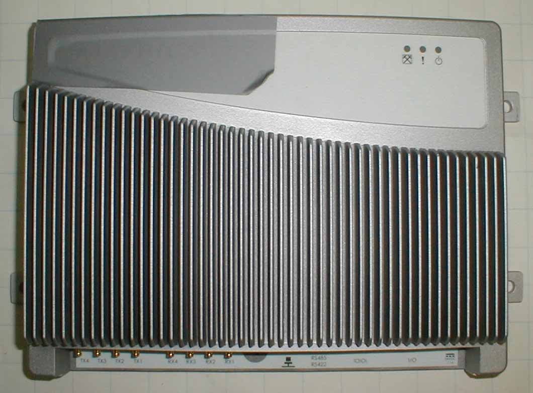
PYFAR400US
Jul 20, 2004FHSS RFID Reader
Equipment Class
DSS - Part 15 Spread Spectrum Transmitter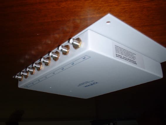
PYFRDR090
Feb 18, 2003Tag Reader
Equipment Class
TNB - Licensed Non-Broadcast Station Transmitter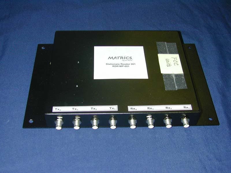
PYFRDRMP001
Feb 19, 2002Frequency Hopping Spread Spectrum Transmitter
Equipment Class
DSS - Part 15 Spread Spectrum Transmitter