PYFRDR090Tag Reader
Symbol Technologies, Inc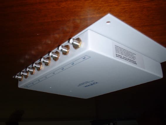
Click to zoom
Application Details
- Equipment Class
- TNB - Licensed Non-Broadcast Station Transmitter
- Date of Grant
- Feb 18, 2003
- Application Purpose
- Original Equipment
- Date of Application
- Feb 18, 2003
- Equipment Note
- Tag Reader
- Frequency Range
- 911.85000000 - 919.85000000
- Company
- Symbol Technologies, Inc
- Country
- United States
Documents & Files
Document Text
Text extracted from the exhibit documents filed with the FCC. Open a document above to read the original.
Users Manual
Long Range Reader User’s Manual Published: November 26, 2002 Document Control Number: MNI02H006 Matrics, Inc. 8850 Stanford Boulevard Suite 3000 Columbia, MD 21045 Tel: 410.872.0300 Fax: 410.872.0700 http://www.matrics.com Notices Copyright 2002 Matrics, Inc. All rights reserved. This document is protected by copyright with all rights reserved. No part of the document may be reproduced or transmitted by any means or in any form without prior consent in writing from Matrics, Inc. Trademarks Matrics is a trademark of Matrics, Inc. All other product names or logos mentioned herein are used for identification purposes only, and are the trademarks of their respective owners. Statement of Rights IMPORTANT – READ CAREFULLY: Matrics products incorporate technology that is protected by U.S. patent and other intellectual property (IP) rights owned by Matrics, Inc, and other rights owners. Use of these products constitutes your legal agreement to honor Matrics’ IP rights as protected by applicable laws. Reverse engineering, decompiling, or disassembly of Matrics products is strictly prohibited. Violators will be prosecuted. ii Long Range Reader User’s Manual 2002 Matrics, Inc. Contents SECTION 1. INTRODUCTION................................................................................................1 Document Conventions..................................................................................................1 Acronyms and Abbreviations........................................................................................1 Disclaimer ......................................................................................................................1 S ECTION 2. SYSTEM DESCRIPTION.....................................................................................2 Product Description.......................................................................................................2 SECTION 3. SPECIFICATIONS AND DIAGRAMS....................................................................3 Reader Specification......................................................................................................3 LEDs and Connectors....................................................................................................3 Reader Diagram.............................................................................................................4 Connections Diagram.....................................................................................................5 S ECTION 4. GETTING STARTED...........................................................................................6 What’s Included?...........................................................................................................6 S ECTION 5. INSTALLATION..................................................................................................7 Mount the Reader...........................................................................................................7 Connect Antenna(s) to the Reader.................................................................................8 Connect the Reader to a Host Computer.......................................................................8 Power On (and Off) the Reader.....................................................................................8 Verify the Reader Installation........................................................................................9 Reader On?.........................................................................................................................9 Test Read Range.................................................................................................................9 SECTION 6. CAUTIONS, NOTES, AND APPROVALS............................................................10 SECTION 7. WARRANTIES AND RETURNS.........................................................................11 Limited Warranty.........................................................................................................11 Return Material Authorization (RMA)........................................................................11 S ECTION 8. TROUBLESHOOTING.......................................................................................12 S ECTION 9. CONTACT US..................................................................................................13 Long Range Reader User’s Manual 2002 Matrics, Inc. iii This page left intentionally blank. iv Long Range Reader User’s Manual 2002 Matrics, Inc. Section 1. Introduction This Long Range Reader User’s Manual, designed for the Matrics RFID System end-user, describes the Long Range Reader (PN: RDR-090) and how to install it. Document Conventions The following conventions are used in this User’s Manual: CONVENTION DESCRIPTION 1. Numbered list Provides step-by-step procedures for performing an action • Bulleted list Provides grouped information, not procedural steps Acronyms and Abbreviations The following acronyms and abbreviations are used in this User’s Manual: ACRONYM DEFINITION IC Integrated Circuit MVM Matrics Visibility Manager OOK On Off Keyed RFID Radio Frequency Identification TBD To Be Determined Disclaimer While Matrics has committed its best efforts to providing accurate information and timely updates to this User’s Manual, we assume no responsibility for any inaccuracies that may be contained herein, and we reserve the right to make changes to this User’s Manual without notice. Long Range Reader User’s Manual 2002 Matrics, Inc. 1 Section 2. System Description Matrics develops and markets Radio Frequency Identification (RFID) solutions that are effective and affordable by offering a combination of low cost, long read range, and a very high read rate unmatched by other RFID systems. A Matrics RFID System gives you real-time, end-to-end visibility of products and assets in your factory, distribution center, retail outlet, or other …
Text truncated - open the document above for the full version.
Block Diagram
SP3TSPDT ATTN ATTN ATTN IQ MOD IQ DEMOD ATTN RX-I RX-Q TO BASEBAND TX-I TX-Q TO BASEBAND PA ANT 1 ANT 2 ANT 3 RF AGILE LO 350MHz SAW FILT 700MHz IF LO AGC 700MHz IF LO AGC SPDT BALUN SPDTSPDT PAD PADSPDTPAD PAD Receiver Transmitter Antenna Switch SP3TSPDT ATTN ATTN ATTN IQ MOD IQ DEMOD ATTN RX-I RX-Q TO BASEBAND TX-I TX-Q TO BASEBAND PA ANT 1 ANT 2 ANT 3 RF AGILE LO 350MHz SAW FILT 700MHz IF LO AGC 700MHz IF LO AGC SPDT BALUN SPDTSPDT PAD PADSPDTPAD PAD Receiver Transmitter Antenna Switch
Cover Letter(s)
8850 Stanford Boulevard Suite 3000 Columbia, MD 21045 Tel: 410.872.0300 Fax: 410.872.0700 www.matrics.com Monday, February 10, 2003 REQUEST FOR CONFIDENTIALITY To Whom It May Concern: Matrics, Inc. requests confidentiality with regard to the following documents in the filing for equipment approval identified by FCC ID. No. PYFRDR090. (1) Schematic diagrams file labeled “ID ZIP RF BOARD V1.PDF” It is the opinion of Matrics Inc. that disclosure of this information would result in significant loss of revenue. This information should be kept confidential for a period of three (3) years. Regards, Kevin Powell Senior Manager, Product Development
Internal Photos
THERE ARE NO COMPONENTS ON THE REVERSE OF THIS BOARD
Operational Description
Operational Description Matrics, Inc. technology makes Radio Frequency Identification (RFID) effective and affordable by offering a combination of low cost, long read range, and a very high read rate unmatched by other RFID systems. A typical Matrics, Inc. RFID system consists of three components: *Silicon-based RFID tags, *Reader network components (readers, antennas, cables, power supplies, wire blocks, etc.), and *Your choice of Host/PC controller with system management software. Tags can be purchased as thin, flexible smart label inlays that can be incorporated into standard laminated paper or plastic to create inexpensive stick-on or embedded labels. Matrics, Inc. smart labels can uniquely identify items up and down the supply chain, such as products in-process, pallets, boxes, trays, and totes. With an innovative approach that removes the circuit complexity from the integrated circuit (IC), Matrics, Inc. UHF tags are simple and inexpensive to produce. The ultra lean chip design requires low power and consequently produces powerful read ranges. Each chip is extremely secure and tamperproof, because the unique ID is programmed very early in the manufacturing process and cannot be altered. The Matrics, Inc. RFID Tag Reader provides all of the RF and control functions required to power and communicate with Matrics, Inc. passive RFID tags. It sends digital data to the tag via the antenna on a pulse width modulated On Off Keyed (OOK) transmitter signal, demodulates the identification signal received from the tag, and then sends the data to a host control device. The Matrics, Inc. Reader system is structured to allow for flexibility in system configurations and in the arrangement of read points to optimize coverage at a low overall cost. Four high performance antennas can be attached to one reader that support a total of thirty-two (32) low performance antennas. The system also employs a unique, patented reader-driven interrogation protocol that allows up to one thousand (1,000) tags to be read each second. This powerful read rate supplies the muscle to overcome interference in noisy environment, and to guarantee acceptable read rates at each read point when large numbers of antennas are multiplexed together. Readers can be powered either locally or through the network cable in the event there is not a local power source near by, and to minimize overall network infrastructure costs.
Parts List/Tune Up Info
8850 Stanford Boulevard Suite 3000 Columbia, MD 21045 Tel: 410.872.0300 Fax: 410.872.0700 www.matricsrfid.com To Whom It May Concern: The following is a procedural notice on adjustments to the Matrics reader RDR-090. Matrics has designed the reader RDR-090 such that all adjustments are made during production and are not allowed to occur post-production in the end user environment. Qualified personnel only make board adjustments. These adjustments are made in a test and measurement environment with appropriate equipment at the final point of assembly for each unit. These adjustments are made to bring each unit into Matrics specification for performance and tolerances. Once these adjustments are made, the unit is closed with multiple screws preventing easy access. In addition, a “void” sticker is placed across the chassis at the point where two halves separate for access. This is a special tamper proof sticker that indicates opening of the unit. Opening of the unit is forbidden and will void any warrantee. Matrics does not distribute adjustment procedures, as the end user is not intended to gain access or have the appropriate equipment to ensure good results. Under the above conditions, Matrics hereby states that all adjustments will take place at the point of final assembly (factory), with the same consistency from unit to unit, and Matrics has put into place precautions to guard against tampering of the device by the end user. Kevin J. Powell Senior Director, Product Development
RF Exposure Info
Prediction of MPE limit at a given distance Equation from page 18 of OET Bulletin 65, Edition 97-01 where:S = power density P = power input to the antenna G = power gain of the antenna in the direction of interest relative to an isotropic radiator R = distance to the center of radiation of the antenna Maximum peak output power at antenna input terminal:33.50 (dBm) Maximum peak output power at antenna input terminal: 2238.721 (mW) Antenna gain(typical):6 (dBi) Maximum antenna gain: 3.981072 (numeric) Prediction distance:200 (cm) Prediction frequency:915 (MHz) MPE limit for uncontrolled exposure at prediction frequency:0.6 (mW/cm^2) Power density at prediction frequency: 0.017731 (mW/cm^2) 2 4R PG S
Test Report
Master: ktlPT90PLMT Date: April 19, 1999 Nemko Test Report: 2L0630RUS1 Applicant: Matrics, Inc. 8850 Stanford Blvd. Suite 3000 Columbia, Md. 21045 Equipment Under Test: Long Range Reader (E.U.T.) In Accordance With: FCC Part 90 Tested By: Nemko Dallas Inc. 802 N. Kealy Lewisville, TX 75057-3136 Authorized By: Tom Tidwell, Frontline Manager Date: 2/6/03 Total Number of Pages: 27 Nemko Dallas FCC PART 90 Non Multilateral Transmitters EQUIPMENT: Long Range Reader PROJECT NO.: 2L0630RUS1 Page 2 of 27 Table of Contents Section 1. Summary of Test Results ....................................................................................... 3 Section 2. General Equipment Specification .......................................................................... 5 Section 3. RF Power Output ................................................................................................... 7 Section 4. Occupied Bandwidth.............................................................................................. 9 Section 5. Spurious Emissions at Antenna Terminals .......................................................... 10 Section 6. Field Strength of Spurious Emissions.................................................................. 14 Section 7. Test Equipment List ............................................................................................. 17 ANNEX A - TEST METHODOLOGIES..................................................................................... 18 ANNEX B - TEST DIAGRAMS.................................................................................................. 24 Nemko Dallas FCC PART 90 Non Multilateral Transmitters EQUIPMENT: Long Range Reader PROJECT NO.: 2L0630RUS1 Page 3 of 27 Section 1. Summary of Test Results Manufacturer: Matrics, Inc. Model No.: Long Range Reader Serial No.: None General: All measurements are traceable to national standards. These tests were conducted on a sample of the equipment for the purpose of demonstrating compliance with FCC Part 90, Subpart I. New Submission Production Unit Class II Permissive Change Pre-Production Unit THIS TEST REPORT RELATES ONLY TO THE ITEM(S) TESTED. THE FOLLOWING DEVIATIONS FROM, ADDITIONS TO, OR EXCLUSIONS FROM THE TEST SPECIFICATIONS HAVE BEEN MADE. None See “ Summary of Test Data”. Nemko Dallas Inc. authorizes the above named company to reproduce this report provided it is reproduced in its entirety and for use by the company’s employees only. Any use which a third party makes of this report, or any reliance on or decisions to be made based on it, are the responsibility of such third parties. Nemko Dallas Inc. accepts no responsibility for damages, if any, suffered by any third party as a result of decisions made or actions based on this report. This report applies only to the items tested. Nemko Dallas FCC PART 90 Non Multilateral Transmitters EQUIPMENT: Long Range Reader PROJECT NO.: 2L0630RUS1 Page 4 of 27 Summary Of Test Data NAME OF TEST PARA. NO. SPEC. RESULT RF Power Output 90.205 Determined at licensing Audio Frequency Response TIA EIA- 603.3.2.6 N/A Audio Low-Pass Filter Response TIA EIA- 603.3.2.6 N/A Modulation Limiting TIA EIA- 603.3.2.6 N/A Occupied Bandwidth 90.210 Mask K (-25 dBm) Complies Spurious Emissions at Antenna Terminals 90.210 Mask K (-25 dBm) Complies Field Strength of Spurious Emissions 90.210 Mask K (-25 dBm) Complies Frequency Stability 90.213 N/A N/A Transient Frequency Behavior 90.214 N/A Frequency stability test not required per 90.213 note 13: Fixed non-multilateration transmitters with an authorized bandwidth that is more than 40 kHz from the band edge, intermittently operated hand-held readers, and mobile transponders are not subject to frequency stability restrictions. . Nemko Dallas FCC PART 90 Non Multilateral Transmitters EQUIPMENT: Long Range Reader PROJECT NO.: 2L0630RUS1 Page 5 of 27 Section 2. General Equipment Specification Transmitter Supply Voltage Input: 24 Vdc Frequency Range: 911.85 MHz to 919.85 MHz Tunable Bands: 911.85 MHz to 919.85 MHz Frequency hopper Necessary Bandwidth: 253 kHz Type(s) of Modulation: F3E (Voice) F1D F2D D7W (QAM) Other Emission Designator: 253KF1D Output Impedance: 50 ohms RF Power Output (rated): 2 Watts Channel Spacing(s): 500 kHz Operator Selection of Operating Frequency: None Power Output Adjustment Capability: None Nemko Dallas FCC PART 90 Non Multilateral Transmitters EQUIPMENT: Long Range Reader PROJECT NO.: 2L0630RUS1 Page 6 of 27 Modifications Made During Testing A high pass filter was added to eliminate spurious emissions. System Description The Matrics Long Range Reader (PN: RDR-090) is an industrial strength fixed Reader targeted to indoor applications, such as warehouses. The Reader offers superior and robust read range capabilities, anti-collision features, and very high data read rates unmatched by other systems. It can be easily mounted in areas of ingress and egress where large numbers of tagged objects are inbound or outbound in a logistics process. It is packaged ready to be interfaced to your host computer, and can easily be programmed to perform specific tasks. The Reader provides all of the RF and control functions required to power and communicate with Matrics passive RFID tags (PN: SDR-001 and DDS-001.) It sends digital data to the tag (through one antenna at any given time) on a pulse width modulated On Off Keyed (OOK) transmitter signal, demodulates the identification signal received from the tag, and then sends the data to your host computer. System Diagram Nemko Dallas FCC PART 90 Non Multilateral Transmitters EQUIPMENT: Long Range Reader PROJECT NO.: 2L0630RUS1 Page 7 of 27 Section 3. RF Power Output NAME OF TEST: RF Power Output PARA. NO.: 2.985 TESTED BY: David Light DATE: Measurement Results: Complies. Measurement Data: Frequency (MHz) Measured Power (dBm) Rated Power (dBm) Measured/Rated (dB) 915.37 33.5 33 1.02 Note: The input supply voltage was varied +/- 15% with no effect on output power. Mea…
Text truncated - open the document above for the full version.
Contact Information
Applicant
Qianlin Zhou(Regulatory Specialist)
Technical Contact
Nemko Dallas, IncDavid Light
[email protected]972-436-9600
802 N. Kealy · Lewisville, Texas · United States
Non-Technical Contact
Nemko Dallas, IncDavid Light
[email protected]972-436-9600
Test Firm
Nemko Dallas, Inc.Michael Cantwell
Technical Specifications
| # | Rule Parts | Frequency Range | Power Output | Emission | Tolerance |
|---|---|---|---|---|---|
| 1 | 90.210 | 911.85 MHz - 919.85 MHz | 2 W | 253KF1D | 2.5000000000 ppm |
Other Applications from Symbol Technologies, Inc
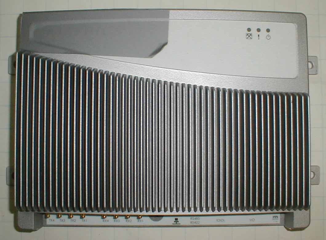
PYFAR400US
Jul 20, 2004FHSS RFID Reader
Equipment Class
DSS - Part 15 Spread Spectrum Transmitter
PYFRDRRUG100
Oct 13, 2003Ruggedized RFID Reader
Equipment Class
LMS - Part 90 Location & Monitoring Transmitter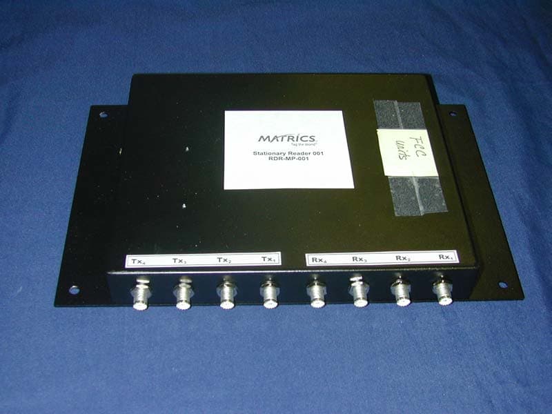
PYFRDRMP001
Feb 19, 2002Frequency Hopping Spread Spectrum Transmitter
Equipment Class
DSS - Part 15 Spread Spectrum Transmitter