PZLM9610Land Mobile Transmitter
EADS-Defense & Security Networks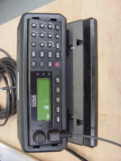
Click to zoom
Application Details
- Equipment Class
- TNB - Licensed Non-Broadcast Station Transmitter
- Date of Grant
- Aug 15, 2002
- Application Purpose
- Original Equipment
- Date of Application
- Jun 23, 2002
- Equipment Note
- Land Mobile Transmitter
- Frequency Range
- 440.00000000 - 490.00000000
- Country
- France
Documents & Files
Document Text
Text extracted from the exhibit documents filed with the FCC. Open a document above to read the original.
Users Manual
User Guide + 2 1 D IR GRP C LR VAL 3 5 6 7 8 0 9 4 EXT F M EN U MC 2610 T U V M N O J K L G H I D E F A B C P Q R S W X Y Z CCP MC 2610 V35/EN CCP MC2 V35 EN LB 17/10/01 14:12 Page 1 NOTICES TO BE READ BEFORE USE SAFETY • Do not use or start up the terminal in an environment exposed to explosion hazards or near explosive equipment. MNC disclaims all responsibility if the equipment is used in non- observance of such instructions, or of this manual in general. PRECAUTIONS • The terminal is to be used only with accessories approved by the manufacturer. Using other accessories may be dangerous and will void the warranty. FUNCTIONS AVAILABLE The functions available on the terminal depend on the options available on the network and on the customisation of each terminal. Only authorised functions appear on the terminal. CCP MC2 V35 EN LB 17/10/01 14:12 Page 2 Functions of the keys Display How to use the terminal How to place a call Receiving a call or a message Open Channel or Group Menu Scan Direct Menu Memory Menu Message Menu Extension Menu Terminal Menu ex 4 5 Contents 103 110 112 114 Procedure in the event of a problem Tips Definitions Index 7 15 23 31 51 59 89 93 67 73 CCP MC2 V35 EN LB 17/10/01 14:12 Page 3 Functions of the keys 4 VAL DIR GRP CLR EXT F MENU + - 1 4 7 3 6 9 2 5 8 0 End (3) Terminal Menu Memory Menu Flash priority Extension Menu External Address: Telephone call (2) Cancel – Clear Next – Scroll Validate (1) The key can be replaced by the key. (2) Optional. (3) The key can be replaced by the key. (4) The key can be replaced by the key. (5) The key is used to activate or deactivate the transmit indicator light on the LS/micro. Direct Menu Keys absent from the basic CCP version On LED Receive LED Transmit LED Volume control Transmit LED Microphone Controls the transmit light indicator (5) PUSH-TO-TALK End Loudspeaker On/Off button + Call selector Open Channel Menu or Group Menu (depending on option) (1) Emergency call (long press) Send- Answer (4) Change in registration base station Multi-party call Scan Message Menu (2) GRPCONF END SEND MC 2610 Aplha- numeric keypad (depending on model) B C A E F D K L J U V T H I G N O M R S P Y QX Z W CCP MC2 V35 EN LB 17/10/01 14:12 Page 4 5 Display Active call S: Base Station Connected d: direct mode power min. D: Direct mode power max. T: Telephone I: Independent digital repeater I Received field strength (BSC connected mode) Message linesStatus line SMS message received Forwarding R MC2600** S39R Registration (2) Fallback modes (1) Received call (1) The letter I is steady on when the cell is in fallback mode 2: coverage is reduced for group calls and operator calls are no longer possible, The letter I flashes when the cell is in fallback mode 3: • fallback mode 3.1: only group calls placed before the switch to fallback mode are maintained, and their coverage is reduced to the active cell, • fallback mode 3.2: it is not possible to place any call; only one channel with coverage limited to the active cell is open. (2) The symbol flashes when waiting for registration (optional). Call selector position (from 01 to 99) S External loudspeaker Ring Tone active Silence CCP MC2 V35 EN LB 17/10/01 14:12 Page 5 CCP MC2 V35 EN LB 17/10/01 14:12 Page 6 Starting the terminal Turning off the terminal Volume control Adjusting the volume of the ringing tones, tones and beeps9 Adjusting the voice volume9 Adjusting the external loudspeaker volume9 Entering a call reference Entering an address (individual call, multi-party call)10 Entering an open channel number (depending on the option)10 Entering a group number (depending on the option)10 Entering a channel number in direct or IDR mode (depending on the option)10 Procedure for using the alphanumeric keypad Using thekey While entering a character (depending on V35 software version) 12 While displaying a menu12 While displaying an information message12 Using the call keys (Push-to-talk,,and ) Using the call selector Using the menus To select a menu13 Audible signals (ringing tones, tones and beeps) Ringing tones14 Tones14 Beeps14 CLR 8 9 8 10 12 11 12 13 13 14 How to use the terminal 7 CCP MC2 V35 EN LB 17/10/01 14:12 Page 7 STARTING THE TERMINAL • Pressthe call selector. The terminal emits an information beep. The message “ WWAAIITT ” and the address of the terminal flash for a few seconds (terminal initialisation). The home message is then displayed: •if the terminal is under network coverage: the registration symbol and the received field strength are displayed, •otherwise, the registration symbol and the received field strength are not displayed. The terminal is under The terminal is not under network coveragenetwork coverage When the terminal is registered, the call selector returns to the last position selected before the terminal was turned off. If a call was associated with this position, it is automatically sent. N.B.: Any of the following messages may be displayed in place of the home message: •" RREECCEEIIVVEEDD MMEESSSSAAGGEESS ": the terminal has received one or more messages (see Message Menu chapter) •" RREECCEEIIVVEEDD CCAALLLLSS ": the terminal has received one or more calls (see Message Menu chapter) •" FFOORRWWAARRDDEEDD ": if the " FFOORRWWAARRDD " function has been deactivated (see Main Menu to deactivate it) TURNING OFF THE TERMINAL • Pressand hold downthe call selector. The terminal emits an information beep, then switches off. On/Off button Call selector MC 2610 How to use the terminal 8 **MMCC22660000** 0011 **MMCC22660000** 0011 778800225500330000 WWAAIITT CCP MC2 V35 EN LB 17/10/01 14:12 Page 8 VOLUME CONTROL Theandkeys are used to adjust individually the level of the ringing tones, tones and beeps, the voice volume and that of the external loudspeaker if one is used with the CCP (optional). There are 8 levels, which are stored in the terminal when it is switched off. The external loudspeaker must be activated or deactivated using the " LLOOUUDDSSPPEEAAKKEERR " function in the Te…
Text truncated - open the document above for the full version.
Users Manual
Résumé / Commentaires : Ce document est réalisé au format A5, excepté les pages internes. Mots clefs : Référence : MC9/TR/APP/00030 Version : 01.05/QL Type : IH Soc. : MNC Produit : MC9635 Titre : Réf. ext. : PS8432EAE01 État : Approuvé Cat. : Externe Mots clefs : AUTEUR : G. BOSSON06/09/01 DOCUMENTALISTE : N. APPERT Préparé par : Date :Approuvé par :Date :Autorisé par :Date : RESPONSABLE TECHNIQUE : B. MARTINEZ RESPONSABLE QUALITÉ : E. BRECHARD RESPONSABLE LoP ou AFFAIRE : A. FRANÇOIS Phase ou Palier : Nb Pages Int.Doc ENDoc FRDoc ESDoc DEPlanchesNotes Total repro A4 Avertissement :En l’absence d’indication contraire, cette nouvelle édition annule et remplace l’édition précédente qui doit être détruite, ainsi que les copies faites à vos collaborateurs. La version / édition précédente n’est pas obsolète. 432323232112147 Matrice DIO.SL A5 : 03.03/FR_EN_ES_DE de 11/2000 MATRA NORTEL COMMUNICATIONS MOBILE TERMINAL INSTALLATION HANDBOOK (BER VERSION B) NOTICE D’INSTALLATION DES TERMINAUX MOBILES (BER VERSION B) PdG CE 2 ii PageMOBILE TERMINAL INSTALLATION HANDBOOK (BER VERSION B) NOTICE D’INSTALLATION DES TERMINAUX MOBILES (BER VERSION B) MC9/TR/APP/00030 06/09/0101.05/QL DOCUMENTS CONNEXES DOCUMENTS APPLICABLES Procédure de Réalisation de la Documentation Exploitant PMR/GEN/PCD/0007201.04/FR Maîtrise de la Documentation Exploitant de PMR/F PMR/GEN/PCD/0001404.01/FR Guide de Rédaction d’un Document Exploitant PMR/GEN/MEG/0005501.01/FR DOCUMENTS DE RÉFÉRENCE Architecture Physique du Terminal MC9 MC9/TR/DD/001801.02/FR Specification for speaker microphone MC9/PRO/APR/002802.02/EN Plan de développement CCP et BER/support simplifiés pour terminaux radio MC9600 MC9/PRO/DPL/007701.01/FR System Requirement specification PCG/SYS/DD/00102.01/EN Mobile control head commercial specification MC9/PRO/APR/008001.02/EN Compte rendu de la revue gate 0A du CCP MC9/PRO/GES/010501.01/FR Dictionnaire du système MC9/PRO/APP/000103.03/FR Cahier des charges de Rédaction BER large bande PMR/DSS0/DOC/CDCR/GB/001.0022431/05/01 iii PageMOBILE TERMINAL INSTALLATION HANDBOOK (BER VERSION B) NOTICE D’INSTALLATION DES TERMINAUX MOBILES (BER VERSION B) MC9/TR/APP/00030 06/09/0101.05/QL PAGE D’ÉVOLUTION INTERNE VERSIONDATECOMMENTAIRES CHAPITRE CONCERNÉ AUTEUR 01.01/0127/06/97Création.0 à 7G. BOSSON 01.01/FR15/07/97Mise à jour suite à vérification du 11/07/97 CRR : MC9/TR/DJD/0173. 0 à 5G. BOSSON 01.02/0105/01/98Mise à jour suite à FR9709–01.0 à 5G. BOSSON 01.02/FR18/02/98Mise à jour suite à vérification du 20/01/98 CRR : MC9/TR/DJD/0173 – 01.02/FR. 0 à 5G. BOSSON 01.03/FR – Document non disponible en langue FR, mais disponible en langue ES. 0 à 5G. BOSSON 01.04/QL03/11/00Passage de la notice en version quadrilingue et au format A5. Prise en comptes des évolutions suivantes : •introduction du CCP Easy +, des terminaux Siemens et MHA (support BER HR6237 et câble système CCP HG4354A), •modification de la composition des kits principaux (suppression des guides et mémos), •ajout du BER RA1621. 0 à 5G. BOSSON 01.05/0121/08/01Ajout du BER large bande et du CCP configuré SMS. Corrections de divers erreurs. 0 à 5G. BOSSON 01.05/QL06/09/01Prise en compte des remarques suite à la vérification du document (voir compte–rendu MC9/TR/APP/00030 01.05/01/CRR). Ajout des traductions. 0 à 5G. BOSSON iv PageMOBILE TERMINAL INSTALLATION HANDBOOK (BER VERSION B) NOTICE D’INSTALLATION DES TERMINAUX MOBILES (BER VERSION B) MC9/TR/APP/00030 06/09/0101.05/QL PAGE LAISSÉE INTENTIONNELLEMENT BLANCHE F E E N G L I S H R A N Ç A I S S P A Ñ O L D E U T S C H PMR Operation Documentation IH – PS8432EAE01 09/2001 Mobile Terminal Installation Handbook (BER Version B) Notice d'Installation des Terminaux Mobiles (BER Version B) InstrucciÛn de InstalaciÛn de los Terminales MÛviles (BER VersiÛn B) Installationsanleitung der Mobilen Endger‰te (BER Version B) MC9/TR/APP/00030 01.05/QL F E E N G L I S H R A N Ç A I S S P A Ñ O L D E U T S C H 09/2001 IH – PS8432EAE01 EQUIPMENT COMPLIANCE TO EUROPEAN STANDARDS The equipment used for the configurations described in this document complies with the following European directive: •“Radio Terminal and Telecommunications Equipment” (R&TTE) Directive no. 1999/5/CE. Tests carried out have proven that the equipment complies with one or more of the following standards related to this directive: EN301489–5, EN55022, EN 55024, EN61000–3–2, EN61000–3–3, EN60950, or EN60335–1 and EN60335–29, EN300113–1/2 and recommendation 1999/519/CE (EMF). During installation, the correct procedures must be followed in order to maintain compliance with European requirements. CONFORMITÉ DES ÉQUIPEMENTS AUX DIRECTIVES EUROPÉENNES Les équipements constituant les différentes configurations décrites dans ce document sont conformes à la directive européenne suivante : •Directive “Equipements Terminaux Radio et de Télécommunications” (R&TTE) n° 1999/5/CE. Les tests effectués ont prouvé que les équipements sont conformes à une ou plusieurs des normes suivantes relatives à cette directive : EN301489–5, EN55022, EN55024, EN61000–3–2, EN61000–3–3, EN60950 ou EN 60335–1 et EN60335–29, EN300113–1/2 et recommandation 1999/519/CE (EMF). Lors des installations, il est impératif de respecter les règles de l’art en matière d’installation afin de conserver la conformité aux exigences européennes. CONFORMIDAD DE LOS EQUIPOS CON LAS DIRECTIVAS EUROPEAS Los equipos incluidos en las diferentes configuraciones descritas en el presente documento están en conformidad con la directiva europea siguiente: •Directiva “Equipos Terminales Radio y de Telecomunicaciones” (R&TTE) n°1999/5/CE. Las pruebas efectuadas han demostrado que los equipos son conformes a una o a varias de las normas siguientes, relativas a dicha directiva: EN301489–5, EN55022, EN55024, EN61000–3–2, EN61000–3–3, EN60950 o EN 60335–1 y EN60335–29, EN300113–1/2 y recomendación 1999/519/CE (EMF). Para efectuar la instalación se debe imperativamente respetar las reglas correspondientes para conservar la confor…
Text truncated - open the document above for the full version.
Users Manual
Résumé / Commentaires : Ce document est réalisé au format A5, excepté les pages internes. Mots clefs : Référence : MC9/TR/APP/00033 Version : 01.05/QL Type : IH Soc. : MNC Produit : MC9600 Titre : Réf. ext. : PS8433EAE01 État : Approuvé Cat. : Externe Mots clefs : AUTEUR : G. BOSSON11/09/01 DOCUMENTALISTE : N. APPERT Préparé par : Date :Approuvé par :Date :Autorisé par :Date : RESPONSABLE TECHNIQUE : B. MARTINEZ RESPONSABLE QUALITÉ : E. BRECHARD RESPONSABLE MARKETING ou AFFAIRE : A FRANÇOIS Phase ou Palier : – Nb Pages Int.Doc ENDoc FRDoc ESDoc DEPlanchesNotes Total repro A4 Avertissement :En l’absence d’indication contraire, cette nouvelle édition annule et remplace l’édition précédente qui doit être détruite, ainsi que les copies faites à vos collaborateurs. La version / édition précédente n’est pas obsolète. 44242424272183 Matrice DIO.SL A5 : 03.03/FR_EN_ES_DE de 11/2000 MATRA NORTEL COMMUNICATIONS FIXED TERMINAL INSTALLATION HANDBOOK NOTICE D’INSTALLATION DES TERMINAUX FIXES PdG CE 2 ii PageFIXED TERMINAL INSTALLATION HANDBOOK NOTICE D’INSTALLATION DES TERMINAUX FIXES MC9/TR/APP/00033 11/09/0101.05/QL DOCUMENTS CONNEXES DOCUMENTS APPLICABLES Sans objet. DOCUMENTS DE RÉFÉRENCE Architecture Physique du Terminal MC9 MC9/TR/DD/001801.02/FR Plan de développement CCP et BER/support simplifiés pour terminaux radio MC9600 MC9/PRO/DPL/007701.01/FR System Requirement specification PCG/SYS/DD/00102.01/EN System Requirement specification PCG/SYS/DD/00102.01/EN Compte rendu de la revue gate 0A du CCP MC9/PRO/GES/010501.01/FR Technical conditions for radio fixed terminal MC9/PRO/APR/0066 Référentiel de la documentation exploitant XXX/PRO/DPL/iiii(selon projet) Dictionnaire du système MC9/PRO/APP/000103.03/FR Cahier des charges de rédaction BER large bande PMR/DSS0/DOC/CDCR/GB/01.00 22405/01 Dossier d’architecture des mobiles LB MC9/TR/DD/21402/01/FR v PageFIXED TERMINAL INSTALLATION HANDBOOK NOTICE D’INSTALLATION DES TERMINAUX FIXES MC9/TR/APP/00033 11/09/0101.05/QL PAGE D’ÉVOLUTION INTERNE VERSIONDATECOMMENTAIRES CHAPITRE CONCERNÉ AUTEUR 01.01/0127/06/97Création.0 à 7G. BOSSON 01.01/FR18/07/97Mise à jour suite à vérification du 11/07/97 CRR : MC9/TR/DJD/0174. 0 à 5G. BOSSON 01.02/0105/01/98Mise à jour suite à FR9709–02.0 à 5G. BOSSON 01.02/FR20/02/98Mise à jour suite à vérification du 30/01/98 CRR : MC9/TR/DJD/0174 – 01.02/FR. 0 à 5G. BOSSON 01.03/FR–Document non disponible en langue FR, mais disponible en langue ES. 0 à 5G. BOSSON 01/04/QL31/10/00Passage de la notice en version quadrilingue et au format A5. Prise en compte des évolutions suivantes : •introduction du CCP Easy +, micro col de cygne ELNO, alimentation bitension et des terminaux Siemens, •modification de la composition des kits “poste principal” (suppression des guides et mémos), •ajout du § caractéristiques, •introduction des BER référence RA16XX. 0 à 5G. BOSSON 01.05/0121/08/01Introduction du BER large bande version A’, version B, CCP alphanumérique. 0 à 5G. BOSSON 01.05/QL11/09/01Prise en compte des remarques suite à la vérification du document (voir compte–rendu MC9/TR/APP/00033 01.05/01/CRR). Ajout des traductions. 0 à 5G. BOSSON vi PageFIXED TERMINAL INSTALLATION HANDBOOK NOTICE D’INSTALLATION DES TERMINAUX FIXES MC9/TR/APP/00033 11/09/0101.05/QL PAGE LAISSÉE INTENTIONNELLEMENT BLANCHE F E E N G L I S H R A N Ç A I S S P A Ñ O L D E U T S C H PMR Operation Documentation IH – PS8433EAE01 09/2001 Fixed Terminal Installation Handbook Notice d'Installation des Terminaux Fixes InstrucciÛn de InstalaciÛn de los Terminales Fijos Installationsanleitung der ortsfesten endger‰te MC9/TR/APP/00033 01.05/QL F E E N G L I S H R A N Ç A I S S P A Ñ O L D E U T S C H 09/2001 IH – PS8433EAE01 EQUIPMENT COMPLIANCE TO EUROPEAN STANDARDS The equipment used for the configurations described in this document complies with the following European directive: •“Radio Terminal and Telecommunications Equipment” (R&TTE) Directive no. 1999/5/CE. Tests carried out have proven that the equipment complies with one or more of the following standards related to this directive: EN301489–5, EN55022, EN 55024, EN61000–3–2, EN61000–3–3, EN60950, or EN60335–1 and EN60335–29, EN300113–1/2 and recommendation 1999/519/CE (EMF). During installation, the correct procedures must be followed in order to maintain compliance with European requirements. CONFORMITÉ DES ÉQUIPEMENTS AUX DIRECTIVES EUROPÉENNES Les équipements constituant les différentes configurations décrites dans ce document sont conformes à la directive européenne suivante : •Directive “Equipements Terminaux Radio et de Télécommunications” (R&TTE) n° 1999/5/CE. Les tests effectués ont prouvé que les équipements sont conformes à une ou plusieurs des normes suivantes relatives à cette directive : EN301489–5, EN55022, EN55024, EN61000–3–2, EN61000–3–3, EN60950 ou EN 60335–1 et EN60335–29, EN300113–1/2 et recommandation 1999/519/CE (EMF). Lors des installations, il est impératif de respecter les règles de l’art en matière d’installation afin de conserver la conformité aux exigences européennes. CONFORMIDAD DE LOS EQUIPOS CON LAS DIRECTIVAS EUROPEAS Los equipos incluidos en las diferentes configuraciones descritas en el presente documento están en conformidad con la directiva europea siguiente: •Directiva “Equipos Terminales Radio y de Telecomunicaciones” (R&TTE) n°1999/5/CE. Las pruebas efectuadas han demostrado que los equipos son conformes a una o a varias de las normas siguientes, relativas a dicha directiva: EN301489–5, EN55022, EN55024, EN61000–3–2, EN61000–3–3, EN60950 o EN 60335–1 y EN60335–29, EN300113–1/2 y recomendación 1999/519/CE (EMF). Para efectuar la instalación se debe imperativamente respetar las reglas correspondientes para conservar la conformidad con las exigencias europeas. ÜBEREINSTIMMUNG DER AUSRÜSTUNGEN MIT DEN EG–RICHTLINIEN Die Ausrüstungen, aus welchen die verschiedenen in diesem Dokument beschriebenen Konfigurationen aufgebaut werden, entsprechen folgenden EG–Richtlinien: •Richtlinie “Fu…
Text truncated - open the document above for the full version.
Cover Letter(s)
TRP/Cetecom bvba June 23, 2002 Federal Communications Commission 7435 Oakland Mills Rd Columbia, MD 21036 Re: Application Filing for FCCID:PZLMC9635 Gentlemen: Gentlemen: Submitted herewith is an application for a Part 90 Land Mobile Transmitter operating in the frequency range of 440 to 490 MHz. The transmitter unit has two configuration arrangements. One configuration is as a mobile unit installed in a motor vehicle while the other configuration uses the same transmitter packaged for a desktop installation. The two models covered by the subject FCC ID are Model MC9635 CS G1 UM (desktop configuration) and Model MC9610 IK G1 UM (mobile configuration) both of which utilize BER (Transceiver Box) RA1336 ABA01 014505755. Where there are differences in documentation between the two configurations, separate files have been submitted to meet the requirements of the FCC Rules. The desktop is designed to be readily relocated. The above configurations were discussed with Mr. Stanley Lyles of the Laboratory staff and after conferring with other FCC staff Mr. Lyles indicated that these configurations could be covered under one FCC ID. A copy of the email correspondence has been submitted with the fileing. This equipment operates with a 12 kHz bandwidth and is subject to a spectral efficiency requirement. A description of the modulation characteristic discussing how the unit meets the spectral efficiency requirement has been submitted with the file together with the confirmation from the FCC that the explanation shows the requirement is met. If there are any questions please contact me at the address above or via phone at 410 531 3439 or email at [email protected]. Sincerely, Phillip Inglis Consultant 14085 Howard Rd Dayton, MD 21036
Cover Letter(s)
Subject: Fwd: EDSN Nortel interpretation Date: Thu, 25 Oct 2001 13:42:47 -0400 From: "Frank Coperich" <[email protected]> To: <[email protected]> CC: "Rich Fabina" <[email protected]> The proposal attached to your incoming inquiry is acceptable for satisfying Section 90.208(j)(8). --------------------------------------------------------------------- Subject: EDSN Nortel interpretation Date: Mon, 22 Oct 2001 09:46:10 -0400 From: <[email protected]> To: [email protected] Frank, Can you confirm the acceptablility of the attached analysis for purposes of showing that the system in question meets the spectral efficiency comparison requirement of Section 90.203(j)(8). It is my understanding that the analysis has been accepted by the FCC. Regards, Phil --------------------------------------------------------------------- Name: 1_spectrum efficiency final_0107201_.doc 1_spectrum efficiency final_0107201_.doc Type: Microsoft Word Document (application/msword) Encoding: base64
Cover Letter(s)
CONFIDENTIALITY REQUEST June 23, 2001 Federal Communications Commission Authorization and Evaluation Division 7435 Oakland Mills Road Columbia, MD 21046 Re:EADS-Defense & Security Networks application for a Part 90 base station transmitter FCC ID: PZLMC9635 Gentlemen: EADS-Defense & Security Networks (EADS-DSN) herein submits an application for Equipment Authorization to be followed by submission of the necessary fees for certification of a base station transmitter under FCC Rules Part 90 as required by the FCC Rules. EADS-DSN requests, pursuant to 47CFR 0.459, post grant confidentiality for portions of the material contained in this application such that the identified material will be withheld from public inspection following the grant of this authorization. This material, as indicated by request for confidentiality of the items during the electronic submission process and further identified below, includes: 1. Circuit diagrams submitted as Equipment Authorization electronic filing attachment: Schematics Part 1 and Schematics Part 2. 2. Parts list submitted as Equipment Authorization electronic filing attachment: "Parts List". 3. Block diagram submitted as Equipment Authorization electronic filing attachment: "Block Diagram". 4. Technical description submitted as Equipment Authorization electronic filing attachment: "Operational Description". 5. Technical description of spectral efficiency submitted as Equipment Authorization electronic filing attachment: "Spectrum Efficiency". 6. Users manual, configurations submitted as Equipment Authorization electronic filing attachments: Users Manual, Mobile installation configuration, and Desktop installation configuration. Specifically, these exhibits contain information relating to circuit function and complexity that could be of benefit to competitors. The material contains trade secrets and confidential information that EADS-Defense & Security Networks does not customarily release to the public and which is otherwise not generally available to the public. Please contact the undersigned by telephone at 410-531-3439, by fax at 410-531-0807, by email at [email protected], or by correspondence at the address below if there are any further questions or additional information needed concerning this filing. Regards, (signed) Phillip Inglis, TRP/Cetecom b.v.b.a. 14085 Howard Rd. Dayton, MD. 21036
Cover Letter(s)
TRP/Cetecom bvba July 14, 2002 Federal Communications Commission 7435 Oakland Mills Rd Columbia, MD 21036 Re: Request to modify application Filing for FCCID:PZLMC9635 Gentlemen: Gentlemen: Submitted herewith is a request to modify the FCC ID referenced above to read as FCCID:PZLM9610. A revised FCC ID label has been submitted to the file. I also wish to correct the referenced model number for the mobile configuration as follows. This modification is due to a change in marketing strategy only. This equipment is a Part 90 Land Mobile Transmitter operating in the frequency range of 440 to 490 MHz. The transmitter unit has two configuration arrangements. One configuration is as a mobile unit installed in a motor vehicle while the other configuration uses the same transmitter packaged for a fixed installation. The two models covered by the subject FCC ID are Model MC9635 CS G1 UM (fixed configuration) and Model MC9610 CS G1 UM (mobile configuration) both of which utilize BER (Transceiver Box) RA1336 ABA01 014505755. Where there are differences in documentation between the two configurations, separate files have been submitted to meet the requirements of the FCC Rules. The above configurations were discussed with Mr. Stanley Lyles of the Laboratory staff and after conferring with other FCC staff Mr. Lyles indicated that these configurations could be covered under one FCC ID. A copy of the email correspondence has been submitted with the fileing. This equipment operates with a 12 kHz bandwidth and is subject to a spectral efficiency requirement. A description of the modulation characteristic discussing how the unit meets the spectral efficiency requirement has been submitted with the file together with the confirmation from the FCC that the explanation is shows the requirement is met. If there are any questions please contact me at the address above or via phone at 410 531 3439 or email at [email protected]. Sincerely, Phillip Inglis Consultant 14085 Howard Rd Dayton, MD 21036
Cover Letter(s)
July 15, 2002 LANGUAGE FOR APPROVAL BY EDSN. DISTANCES BELOW ARE NOMINAL AND MAY BE ADJUSTED AFTER RECEIVING SAR REPORT. FCC RF Exposure Compliance Requirements for Occupational Use Only: This Radio has been evaluated and found to comply with the Federal Communications Commission (FCC) RF exposure limits for Occupational Use/Controlled exposure environment. In addition, it complies with the following Standards and Guidelines: ◊ FCC 96-326, Guidelines for Evaluating the Environmental Effects of Radio Frequency Radiation. ◊ FCC OET Bulletin 65 Supplement C, Evaluating Compliance with FCC Guidelines for Human Exposure to Radio Frequency Electromagnetic Fields. ◊ ANSI/IEEE C95.1-1992, IEEE Standard for Safety Levels with Respect to Human Exposure to Radio Frequency Electromagnetic Fields, 3 kHz to 300 GHz. ◊ ANSI/IEEE C95.3-1992, IEEE Recommended Practice for the Measurement of Potentially Hazardous Electromagnetic Fields - RF and Microwave. 1. This radio is NOT approved for use by the general population in an uncontrolled environment. This radio is restricted to occupational use, work related operations only where the radio operator must have the knowledge to control its RF exposure conditions. 2. When transmitting, insure the radio antenna is 33 centimeters or more away from your head and body. 3. The antenna must be mounted to maintain 3 3 centimeters from any person.
Cover Letter(s)
Responses follow the questions: 1.) RF Exposure Exhibit 11 "Corrected RF Exposure statement" refers to 47 CFR 25.200(d) for satellite systems. Please justify how this applies, or revise. Response: Revised exhibit has been uploaded to the file deleting the incorrect reference to 25.200(d). 2.) RF Exposure Exhibit 11 "RF Exposure Learning statement" states: "This Radio has been tested..." We suggest to change "tested" to "evaluated." Response: Revised exhibit has been uploaded with the suggested change from "tested" to "evaluated". 3.) Your Operational Description specifies a emission designator of 12K0F1D. However, you have requested 12K0G1D on the 731 form. Please clarify. In addition, please justify the necessary bandwidth. Response: Frequency and phase modulation designators are typically used interchangeably. Thus 12K0F1D and 12K0G1D are equivalent. Please refer to the NOTE: at the end of Section 2.201(c )(3). This system is a GMSK system and on a purely technical basis G is the more appropriate designation. Regarding the necessary bandwidth, this was previously determined and accepted by the Commission for two models of base units and one portable unit. GSMK with an 8 KB data rate has a 6.9 kHz occupied bandwidth based on the classic 23 dB down criteria. However, this does not incorporate a factor for the increased spectral efficiency and the bandwidths used in that discussion, accepted by Mr. Coperich, that determined the EADS system met the spectral efficiency requirements. as required by the Part 90 rules. Based on the provisions of 2.202(a) and (b) adjustments in bandwidth specification based on including emissions that are needed to insure the transmission of information at the rate and quality required for the system are permitted. 4.) Your June 23, 2002 request for Confidentiality letter specifies "Exhibit 8" as Confidentiality but this Exhibit contains Users Manual. Please resolve this issue. Response: The users manual is provided with the equipment to assist the personnel (typically law enforcement) in setting up and operating the equipment. However, it is not released to the general public as would be the case with making it available in the public FCC file. EADS does not believe it is in the best interest of the purchasers of this equipment and in particular law enforcement personnel to have this information made available to the general public. If this position is not acceptable to the Commission, please so indicate and a revised request will be submitted. 5.) For Mobile Radio Terminal MC9610 IK G1 UM and Fixed Radio Terminal MC 9635 CS G1 UM, please submit the Substitution Method for radiated spurious emission. Also, please describe your test method for performing this test. Please note that the attenuation requirement for radiated spurious emissions is referenced to the desired signal yielding dBc. The attenuation specification is not XX uV/M, or derived from absolute value of the field strength. The dBc is determined from the substitution method such as described in the ANSI/TIA/EIA-603-A-2001 document. What is needed is a determination of the actual power levels necessary to reproduce these field strength levels. Those power levels (from a signal generator source and a dipole antenna replacing the EUT) are then compared to the power output of the transmitter to determine dBc. That is the basis of the "substitution method". Response: EADS respectfully asks that the stated request should be reconsidered based on the followi…
Text truncated - open the document above for the full version.
Contact Information
Applicant
Yann Lebail(Product Manager)
Technical Contact
TRP/Cetecom bvbaPhillip Inglis
[email protected]4105313439
14085 Howard Rd · Dayton, Maryland · United States
Non-Technical Contact
TRP/Cetecom bvbaPhillip Inglis
[email protected]4105313439
Test Firm
Cetecom ICT Services GmbHRalf Hoehn
Technical Specifications
| # | Rule Parts | Frequency Range | Power Output | Emission | Tolerance |
|---|---|---|---|---|---|
| 1 | 90.210 | 440 MHz - 490 MHz | 10 W | 12K0G1D | 2.5000000000 ppm |
Other Applications from EADS-Defense & Security Networks
PZLM9665
Aug 19, 2002Land Mobile Repeater
Equipment Class
TNB - Licensed Non-Broadcast Station Transmitter
PZLMC9660G2UM
Jan 10, 2002Base Station Transmitter
Equipment Class
TNB - Licensed Non-Broadcast Station Transmitter
PZLMC9620SG2UM
Jan 10, 2002Portable phone used in a networked system
Equipment Class
TNE - Licensed Non-Broadcast Transmitter Held to Ear