PZWDWBT001Bluetooth Module
Denso Wave Incorporated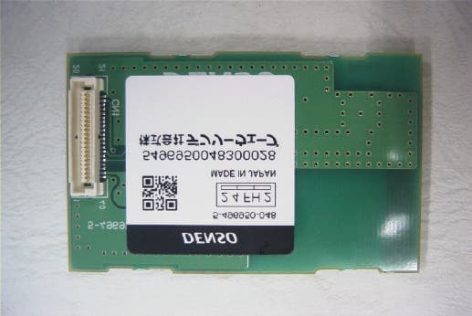
Click to zoom
Application Details
- Equipment Class
- DSS - Part 15 Spread Spectrum Transmitter
- Date of Grant
- Jun 12, 2003
- Application Purpose
- Original Equipment
- Date of Application
- Jun 12, 2003
- Equipment Note
- Bluetooth Module
- Frequency Range
- 2402.00000000 - 2480.00000000
- Company
- Denso Wave Incorporated
- Country
- Japan
Documents & Files
Document Text
Text extracted from the exhibit documents filed with the FCC. Open a document above to read the original.
Users Manual
Installation Description DWBT001 shall be installed in the Bar-code Handy Terminal as shown in Fig. 1. When DWBT001 is installed in the Bar-code Handy Terminal, we as OEM shall consider the following points; 1. Since DWBT001 owns its FCC ID number, we shall affix an exterior label on the outside of the Bar-code Handy Terminal if the FCC ID is not visible. The exterior label shall use wording such as either “Contains FCC IC : PZWDWBT001”. 2. DWBT001 complies with requirements of sub-sections 15.203, 15.205, 15.209 and 15.247 in FCC Rules Part 15. We shall install DWBT001 in accordance with their requirements. 3. DWBT001 complies with requirements of the sub-section 2.1091. When installers install DWBT001 into the Bar-code Handy Terminal, they shall ensure that the public is not exposed to radio frequency energy levels in excess of the Commission’s guidelines in accordance with the sub-section 15.247(b)(4) in FCC Rules Part 15. (1) Assembling Bluetooth Board to holder. (2) Assembling Bluetooth Board assembled holder in Lower Case of Bar-code Handy Terminal. DWBT001 (3) Assembling main circuit board, bar-code scanning module and LCD on lower case of Bar-code Handy Terminal. DWBT001 (4) Assembling Upper Case
Users Manual
Regularoty Information to user DWBT001 is installed in Bar-code handy terminal, so DWBT001 has not manual for user. (Not sale only DWBT001 in US marketplace) FCC user’s manual requirements that are FCC rule Part 15.21 and 15.105 are described on user’s manual of Bar-code Handy terminal. Also SAR caution statement is described on user’s manual of Bar-code Handy terminal. (Please refer following.) FCC and RSS-210 Regulations This device complies with Part 15of the FCC Rules and RSS-210 Rules Operation is subject to the following two conditions : (1) this device may not cause harmful interference, and (2) this device must accept any interference received, including interference that may cause undesired operation. FCC WARNING : Changes or modifications not expressly approved by the party responsible for compliance could void the user’s authority to operate the equipment. NOTE : This equipment has been tested and found to comply with the limits for a Class A digital device, pursuant to part 15 of the FCC Rules. These limits are designed to provide reasonable protection against harmful interference when the equipment is operated in a commercial environment. This equipment generates, uses, and can radiate radio frequency energy and, if not installed and used in accordance with the instruction manual, may cause harmful interference to radio communications. Operation of this equipment in a residential area is likely to cause harmful interference in which case the user will be required to correct the interference at his own expense. Caution : Radio Frequency Exposure This device meets the FCC RF Exposure Guidelines in OET65. This transmitter and its antenna should not be placed next to other antennas or similar radiating structure. ICES-003 Regulation This Class A digital apparatus complies with Canadian ICES-003. Cet appareil numérique de la classe A est conforme à la norme NMB-003 du Canada.
Users Manual
Operation manual 1. Data communication with potable printer. (1) Registration of portable printer and selection of the portable printer - Transmits the registration signal from potable printer and register the portable printer at the BHT-8000. - Transmits the selection signal from BHT-8000 to the portable printer and connect the BHT-8000 with portable printer. (2) Bar code reading and data transfer BHT-8000 reads the bar code and transmits the reading data to portable printer. Portable printer prints the receipt. 2. Data communication in public circuit (1) Registration of cell phone and selection of the cellular phone - Transmits the registration signal from cellular phone and register the cellular phone at the BHT-8000. - Transmits the selection signal from BHT-8000 to the cell phone and connect the BHT-8000 with cellular phone. (2) Bar code reading and call When BHT-8000 reads the bar code, the reading data is transmitted from cellular phone to the host by public circuit. Bar code Bluetooth RF signal Bluetooth RF signal Bluetooth RF signal Cellular RF signal Host modem modem Bar code Components and Functions Release button Press this button to remove the battery cartridge. Touch screen LCD (liquid crystal display) Shows the characters and graphic patterns. You may directly touch the screen with the stylus for data entry. Indicator LED Illuminates in green when the BHT has successfully read a 2D code or bar code. Trigger switch (M4 key) Press this switch to start code reading. Hand strap Be sure to put your hand through this strap to prevent you from dropping the BHT accidentally. Trigger switch (M3 key) Press this switch to start code reading. Optical interface port Used to exchange data/programs with the host computer via its integrated IR port or via the optical communication unit CU-7000. Connector cover Inside this cover is the direct-connect interface port. Rechargeable battery cartridge Main power source of the BHT. Reading window Stylus Built-in antenna Do not cover this antenna section with metal-evaporated tape or by hand. Doing so may result in communications failures. The functions of the keys may be set by user programs. Shown below is a set of sample functions. SF (Shift) key Used in combination with numerical keys for special input procedures. C (Clear) key Clears the last inputted data or returns to the original screen. M1/M2 (Magic) keys Up- and down-arrow keys are assigned to the M1 and M2 keys by default, respec- tively. If the SF key is held down, left- and right-arrow keys are assigned to the M1 and M2 keys, respectively. These keys may be used as an SF key, ENT key, or backlight function on/off key depending upon definition in System Mode or in user programs. They may be also assigned string data in user programs. ENT (Enter) key Finalizes the inputted data or operations, and starts the corresponding processing. PW (Power) key Turns the BHT on or off. Numerical keys Used for numerical input. BS (Backspace) key Moves back one character. 0 $ -% , SP 7 ABC 9 GHI 8 DEF 1 STU 3 YZ 2 VWX ENT 4 JKL 6 PQR 5 MNO PWBS C SF Reading 2D Codes and Bar Codes •The markers show the left-to-right scanning range. When the scanning distance is 8.5 to 9.5 cm (3.3 to 3.7 inches), they indicate almost the center of the up-down scanner’s view. If the distance is out of the range, those markers will deviate from the center. •If the BHT fails to read due to specular effects or other factors, change the scanning angle of the reading window or the distance from codes as shown at right, and try it again. (Specular ef- fects occur when the reflection of the light from the code becomes excessively strong. This can easily happen when the reflecting surface is polished or covered with vinyl.) •The code reading procedure may differ depending upon the application used, so follow the application's manual. Turn the BHT power on, bring the reading window to the target code, and press the trigger switch. The BHT turns three marker LEDs on to indicate the scanning range and the illumination LED to scan the code. Keep the BHT sta- tionary in a position where the target code lies between the right and left markers and the center marker comes to the center of the target code. Hold the reading window 4 to 14 cm (1.6 to 5.5 inches) away from codes to be scanned. When the BHT has read the code successfully, the indicator LED will illuminate in green and the markers will go off. Trigger switch (M3 key) PW key Trigger switch (M4 key) 4 to 14 cm (1.6" to 5.5") Markers Indicator LED Illuminates in green when the BHT has successfully read the code. Touch screen LCD Shows the scanned image of a code lying inside the scanner’s view if the view finder is set to ON. •Before reading 2D codes or bar codes, clean those labels if stained. •Avoid using the BHT in direct sunlight. The BHT might fail to read correctly. •To read 2D codes or bar codes on curved surfaces, apply the BHT to the target code so that the code comes to the center of the scanning range indicated by the markers. •Depending upon the code size or cell pitch, the proper scanning distance from 2D codes or bar codes will differ. At the scanning time, the marker LEDs and illumination LED will come on. The illumination LED may not come on where it is bright enough for the BHT to scan. The light intensity of those LEDs will vary depending upon the scanning conditions and variation of their elements.
Cover Letter(s)
American Telecommunications Certification Body Inc. 6731 Whittier Ave, McLean, VA 22101 June 12, 2003 RE: FCC ID: PZWDWBT001 Attention: Keijiro Kumagai I have a few comments on this Application. 1. In item 4 of your module request letter you state that because the antenna is in the host that it therefore complies with the rules. Please note that this by it self is not sufficient. A module must be tested with the specific antenna used. Please confirm that the antenna mentioned as being in the host is the same antenna with which the module was tested. Please provide some information on the antenna used with this module. Please identify where the antenna is located in a typical host. Please show a photo of the antenna tested. 2. Please note that the setup photos do not clearly identify the module. Please provide setup photos that clearly show the module in stand alone configuration. 3. Several of your plots show a significant amount of ‘noise’. Please verify that this ‘noise’ has not affected the readings in the report. Dennis Ward mailto:[email protected] The items indicated above must be submitted before processing can continue on the above referenced application. Failure to provide the requested information may result in application termination. Correspondence should be considered part of the permanent submission and may be viewed from the Internet after a Grant of Equipment Authorization is issued. Please do not respond to this correspondence using the email reply button. In order for your response to be processed expeditiously, you must submit your documents through the AmericanTCB.com website. Also, please note that partial responses increase processing time and should not be submitted. Any questions about the content of this correspondence should be directed to the sender.
External Photos
Photograph of Bluetooth board Photo of Bluetooth Board (Component side) Photo of Bluetooth Board (Solder side)
ID Label/Location Info
FCC and IC Label location of Bluetooth Board Label Layout on Bluetooth ASSY Unit : mm Fig. Label Layout Note : Compliance statement of marking will not be changed. But marking layout and size may be changed. * Label materials Surface material : PET film Bonding material : Adhesive (MP1) 31.5 33.5 21 Label Location 20 1 40 FCC and IC ID Label layout and location on Handy Terminal Fig. FCC and IC Label Location on Handy Terminal FCC and IC ID Label on Handy Terminal U nit : mm Fig. 4.6.2. FCC and IC ID Label layout Note : Compliance statement of marking will not be changed. But marking layout and size maybe changed. * Label materials Surface material : PET film Bonding material : Adhesive (MP1) 33 10.5 FCC and IC ID Label
Internal Photos
Photograph External Internal (Component side) Internal (Solder side)
Operational Description
Description of each Blocks Functional Explanation of Bluetooth Module IC The following is the outline for design and development. a. Stabilization of Frequency This radio equipment applies Frequency Synthesizer Method to gain frequency stabilization and accuracy. For frequency stabilization, it uses 16MHz crystal oscillator (Crystal Oscillator X100) as a reference signal oscillator in order to control the voltage control oscillator for 1.2GHz band (U100: VCO/PLL part). Every crystal oscillator is adjusted by electrical trimming of loading capacitance of oscillator. The crystal oscillator generates 16MHz reference clock with + - 17ppm stability. b. Suppression of Spurious Emission All Radio frequency circuits of this radio equipment are consisted of one IC chip. Also this radio equipment has a function to amplify RF signal. Therefore Spurious generated in the chip (U100) is canceled out and does not leak. At first this radio equipment converts digital signals to analog signals. Then the converted analog signals pass through LPF (Low Pass Filter) and in transit Spurious (noise signal) of the signals is removed in high frequency band. Additionally since the analog signals always go through BPF (Band Pass Filter) before entering antenna, 2 nd and 3 rd Harmonics generated by Power Amplifier is removed. In addition before shipment we test and check all products for out of band spurious emission during production process. Furthermore a metal shielding case covers RF block and Modulation/Demodulation areas in order to suppress Radiation even more. c. Modulation Control This radio equipment applies the Frequency Hopping Method and uses 79 channels from 2402 to 2480MHz for communication. To stabilize channel frequency at channel switch-over, signals from Power Amplifier in Transmitter is output from Antenna via Switch after frequency of output signal of +45/-45 Phase Shifter in VCO/PLL is stabilized. Following is the procedure of Hopping Sequence. To have homogeneous distribution of radio wave in 79 channels, we repeat sequence using 32 channels of 79 channels (between 2402 to 2480MHz, every 1MHz step) in the pseduo-random way 5 times. In addition to have exact Hopping within the used band we control VCO/PLL in the Chip (U100) from Main Controller. NOTE: Please refer the following information related to FCC requirements. Additional information in accordance with requirements of FCC 15.247 and FCC Public Notice DA 00-705 1. Hopping frequency requirements The number of hopping frequencies is measured in accordance with FCC Public Notice DA 00-705 and reported the compliance in the test report. On pseudorandom frequency hopping sequence the following is an example of a 79 hopping sequence in data transmission mode: 47, 21, 44, 23, 42, 53, 46, 55, 33, 48, 52, 35, 50, 20, 54, 67, 56, 37, 60, 39, 58, 69, 62, 71, 64, 25, 68, 27, 66, 57, 70, 59, 72, 29, 76, 31, 74, 61, 78, 01, 63, 41, 05, 43, 03, 73, 07, 75, 09, 45, 13, 40, 11, 77, 15, 00, 16, 28, 49, 22, 34, 02, 19, 06, 17, 51, 32, 14, 36, 04, 12, 26, 18, 38, 24, 08, 30, 65, 10 Example of a hopping sequence in inquiry mode: 47, 08, 71, 57, 63, 02, 61, 45, 55, 10, 59, 73, 65, 69, 27, 43, 00, 77, 04, 67, 37, 06, 31, 75, 33, 39, 51, 40, 29, 14, 35, 49 Example of a hopping sequence in paging mode: 08, 57, 70, 68, 51, 02, 40, 42, 04, 61, 46, 44, 63, 14, 50, 48, 16, 65, 54, 52, 67, 18, 58, 56, 20, 53, 60, 62, 55, 06, 66, 64 d. Limitation of Transmission Power This radio equipment uses a saturated type power amplifier (PA). Additionally transmit power does not exceed the rated level in the PA block because we control the transmit power from main control block based on the configuration of Flash ROM. Also the Stabilized Power Supply IC (U101) stabilizes supply voltage 1.8V. Moreover the stabilized 1.8V is even more stabilized in the constant voltage circuit inside of the Chip (U100) to prevent transmit power fluctuation caused by voltage fluctuation. e. Suppression of Radio Collaterally Radiated by Receiver As mentioned in the above b., all high frequency circuits of this radio equipment are consisted of one chip and this radio equipment also has a function to amplify high frequency signal. Therefore Radiation generated in the chip (U100) is canceled out and does not leak. Additionally there are Mixer and Low Noise Amplifier between VCO and the Antenna terminal. At reception Inverse Direct Isolation of the Mixer and the Low Noise Amplifier prevents Spurious of VCO/PLL from leaking out from the Antenna terminal. Also a metal shielding case covers Modulator/Demodulator and RF block so that the Radiation decreases.
Operational Description
Product Outline The DWBT001 is the 2.4 GHz wireless LAN transceiver circuit board which uses frequency hopping spread spectrum technology in accordance with the Bluetooth Specification version1.1. This product is installed only in some specified handy terminals. This product connects the handy terminal with the other Bluetooth devices (i.e. portable printer, personal computer, cellular phone, etc.) without using cable. Specification of Product - Product name : Bluetooth Board - Standard based upon : Bluetooth Spec. Ver.1.1 - Product Type No. : DWBT001 - Frequency range : 2402MHz to 2480MHz - Nominal output power : 1mW (0dBm) - Nominal voltage : 3.3 ± 0.3 VD
Test Setup Photos
Test report No. : 23IE0101-HO-1 Page : 14 of 40 Issued date : June 6, 2003 FCC ID : PZWDWBT001 UL Apex Co., Ltd. Head Office EMC Lab. 4383-326 Asama-cho, Ise-shi, Mie-ken 516-0021 JAPAN Telephone : +81 596 24 8116 Facsimile : +81 596 24 8124 Spurious Emission (Radiated) Worst Case Position Z-axis(Vertical) X-axis(Horizontal)
Contact Information
Applicant
Takehiko Koshino(Proj. Mgr, AUTO-ID Business Unit Eng. Plan.Div.)
Technical Contact
UL Apex Co., Ltd.Yoshiaki Iwasa
[email protected]81 596 24 8116
4383-326 Asama-cho · Ise-shi, Mie-ken · Japan
Test Firm
UL Apex Co., Ltd.Toshihiro Ikegami
Technical Specifications
| # | Rule Parts | Frequency Range | Power Output |
|---|---|---|---|
| 1 | 15C | 2.40 GHz - 2.48 GHz | 1.30 mW |
Other Applications from Denso Wave Incorporated
PZWSE1BUBC
Jan 17, 2024RF Tag Handy Scanner
Equipment Class
DSS - Part 15 Spread Spectrum Transmitter
PZWBHTM80QW
Feb 04, 20212D Code Handy Terminal
Equipment Class
DSS - Part 15 Spread Spectrum Transmitter
PZWBHTM80QWG
Jan 27, 20212D Code Handy Terminal
Equipment Class
NII - Unlicensed National Information Infrastructure TX
PZWUR50MERU
Jan 13, 2021Fixed Type RFID Scanner
Equipment Class
DSS - Part 15 Spread Spectrum Transmitter
PZWBHT1200QU
Sep 21, 20152D Code Handy Terminal
Equipment Class
DSS - Part 15 Spread Spectrum Transmitter