PZWDWBT003Bluetooth Transmitter Module
Denso Wave Incorporated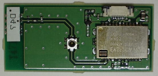
Click to zoom
Application Details
- Equipment Class
- DSS - Part 15 Spread Spectrum Transmitter
- Date of Grant
- Nov 23, 2004
- Application Purpose
- Original Equipment
- Date of Application
- Nov 23, 2004
- Equipment Note
- Bluetooth Transmitter Module
- Frequency Range
- 2402.00000000 - 2480.00000000
- Company
- Denso Wave Incorporated
- Country
- Japan
Documents & Files
Document Text
Text extracted from the exhibit documents filed with the FCC. Open a document above to read the original.
Users Manual
32 Components and Functions Indication LED Illuminates in green when the BHT has successfully read a bar code. Liquid crystal display (LCD) Shows the characters and graphic patterns. Bar-code reading window Trigger switch (M3 key) Press this switch to start bar-code reading. Trigger switch (M4 key) Press this switch to start bar-code reading. IrD A interface port Used to exchange data/programs with the host computer via its integrated IR port or via the optical communication unit CU-300. Hand strap Be sure to put your hand through this strap to prevent you from dropping the BHT accidentally. Connector cover Inside this cover is the direct-connect interface port. Battery cover lock Use this lock to lock/unlock the battery cover. Battery cover Remove this cover to replace the battery cartridge. 33 ENT (Enter) key Finalizes the input data or operations, and starts the corresponding processing. Numerical keys Used for data input. Magic keys (M1 to M4) Each of the M3 and M4 keys is assigned a trigger switch by default. Depending upon definition in System Mode or in user programs, M1 to M4 keys may be used as any of the ENT key, trigger switch, SF key, and backlight function on/off key. These keys can be also assigned string data. Trigger switch (M4 key) Power ke y Turns the BHT on or off. Trigger switch (M3 key) C (Clear) ke y Clears the last inputted data or returns to the original screen. BS (Backspace) key Moves back one character. SF (Shift) ke y Used in combination with numerical keys for special input procedures. Function keys Used for choosing functions. Cursor keys (F5 to F8) Used to move up to the preceding line, down to the next line, to the preceding character, and to the next character. 34 Reading Bar Codes Turn the BHT on, bring the bar-code reading window to the bar code to be scanned, and press the trigger switch. The BHT turns on the illumination LED to scan the bar code. When the BHT has read the bar code successfully, the indicator LED will illuminate in green. • If the BHT fails to read due to specular effects or other factors, change the scanning angle of the reading window or the distance from codes as shown at right, and try it again. (Specular effects occur when the reflection of the light from the bar code becomes excessively strong. This can easily happen when the reflecting surface is polished or covered with vinyl.) • To read bar codes wider than the readable area of the bar-code reading window, pull the bar-code reading window away from bar codes. The BHT can read bar codes at a maximum distance of 45 cm (17.7") from the bar-code reading window, respectively. ** ** Under the following conditions: - Ambient illuminance: 500 lux (fluorescent lamp) - ITF conforming to the UPC Shipping Container Code - PCS value: 0.9 or more - Minimum narrow bar width: 1.2 mm min. (47.2 mils min.) • The bar code reading procedure may differ depending upon the application used, so follow the application’s manual. Illumination range covered by the illumination LED Indicator LED (Illuminates in green when the BHT has read the bar code successfully.) Power ke y Trigger switch (M3 key)* Trigger switch (M4 key)* * The trigger switch function is assigned to both of the M3 and M4 keys by default. 35 • Before reading labels, clean them if stained. • Avoid using the BHT in direct sunlight. The BHT might fail to read correctly. • To read bar codes on curved surfaces, apply the bar-code reading window to the center of each bar code at a right angle. • If you pull the bar-code reading window away from bar codes, the actual scanning range will become narrower than the range covered by the illumination LED. • The light intensity of the illumination LED will vary depending upon the scanning conditions and variation of its elements. 10. Information to user DWBT003 is installed in the handy terminal, so DWBT003 has no user’s manual. FCC user’s manual requirements that are FCC rule Part 15.21 and 15.105 are described on user’s manual of the handy terminal. US and Canada Regulations This device complies with Part 15 of FCC rules, Canada ICES-003 and RSS-210 Rules. Operation is subject to the following two conditions: (1) this device may not cause harmful interference, and (2) this device must accept any interference received, including interference that may cause undesired operation. NOTE : This equipment has been tested and found to comply with the limits for a Class A digital device, pursuant to Part 15 of the FCC Rules. These limits are designed to provide reasonable protection against harmful interference when the equipment is operated in a commercial environment. This equipment generates, uses, and can radiate radio frequency energy and, if no t installed and used on accordance with the instruction manual, may cause harmful interference to radio communications. Operation of this equipment in a residential area is likely to cause harmful interference in which case the user will be required to correct the interference at his own expense. NOTE : This Class A digital device apparatus complies with Canadian ICES-003. Cet appareil numérique de la classe A est conforme à la norme NMB-003 du Canada. FCC WARNING : Changes or modifications not expressly approved by the party responsible fo r compliance could void the user’s authority to operate the equipment. CAUTION : Radio Frequency Radiation Exposure This equipment complies with FCC radiation exposure limits set forth for uncontrolled equipment and meets the FCC radio frequency (RF) Exposure Guidelines in Supplement C to OET65. This equipment has very low levels of RF energy that it is deemed to comply without testing of specific absorption ratio (SAR). Co-location : This transmitter must not be co-located or operated in conjunction with any other antenna or transmitter.
External Photos
7. Photograph 7.1. Photograph of Bluetooth Board Photo. Bluetooth Board (Component Side) Photo. Bluetooth Board (Solder Side) 7.2. Photograph of Bluetooth Module IC Photo 7.2.1. Bluetooth Module IC (External) Photo 7.2.2. Bluetooth Module IC (Internal) Photo 7.2.3. Bluetooth Module IC (Internal)
ID Label/Location Info
9. Marking Layout and Location 9.1. Marking Location on the Bluetooth Board 9.2. Marking Layout on the Bluetooth Board ANT1 FCC ID and IC ID label location 2.4 FH 2 R 496350-3880 DENSO WAVE INC. MADE IN JAPAN S/N : N661 FCC ID:PZWDWBT003 IC:1551C-DWBT003 004NYCA0116 FCC ID and IC ID location L1 9.3. Marking Layout and location of scanner assy Fig. Label Layout of Scanner Assy DENSO WAVE INCORPORATED MADE IN JAPAN Barcode Barcode Data N661 Label location FCC ID:PZWDWBT003 IC:1551C-DWBT003 BHT-300BB 8MB +3.7V 550mA CONTAINS
Internal Photos
7. Photograph 7.1. Photograph of Bluetooth Board Photo. Bluetooth Board (Component Side) Photo. Bluetooth Board (Solder Side) 7.2. Photograph of Bluetooth Module IC Photo 7.2.1. Bluetooth Module IC (External) Photo 7.2.2. Bluetooth Module IC (Internal) Photo 7.2.3. Bluetooth Module IC (Internal)
Test Report
Test report No. : 25AE0222-HO-1 Page : 1 of 39 Issued date : September 30, 2004 FCC ID : PZWDWBT003 Revised date : November 5, 2004 UL Apex Co., Ltd. Head Office EMC Lab. 4383-326 Asama-cho, Ise-shi, Mie-ken 516-0021 JAPAN Telephone : +81 596 24 8116 Facsimile : +81 596 24 8124 MF060b(10.04.03) EMI TEST REPORT Test Report No. : 25AE0222-HO-1 Applicant : DENSO WAVE INCORPORATED Type of Equipment : Bluetooth Board Model No. : DWBT003 Test standard : FCC Part 15 Subpart C Section 15.207, Section 15.247: 2004 FCC ID : PZWDWBT003 Test Result : Complied 1. This test report shall not be reproduced in full or partial, without the written approval of UL Apex Co., Ltd. 2. The results in this report apply only to the sample tested. 3. This equipment is in compliance with above regulation. We hereby certify that the data contain a true representation of the EMC profile. 4. The test results in this report are traceable to the national or international standards. Date of test: Tested by: Naoki Sakamoto EMC Service Approved by : Hironobu Shimoji Group Leader of EMC Service September 14 and 16 , 2004 Test report No. : 25AE0222-HO-1 Page : 2 of 39 Issued date : September 30, 2004 FCC ID : PZWDWBT003 Revised date : November 5, 2004 UL Apex Co., Ltd. Head Office EMC Lab. 4383-326 Asama-cho, Ise-shi, Mie-ken 516-0021 JAPAN Telephone : +81 596 24 8116 Facsimile : +81 596 24 8124 MF060b(10.04.03) CONTENTS PAGE SECTION 1: Client information .................................................................................................................... 3 SECTION 2: Equipment under test (E.U.T.)................................................................................................ 3 SECTION 3: Test specification, procedures & results ................................................................................ 5 SECTION 4: Operation of E.U.T. during testing ......................................................................................... 8 SECTION 5: Conducted Emission................................................................................................................. 9 SECTION 6: Spurious Emission .................................................................................................................. 10 SECTION 7: Bandwidth ............................................................................................................................... 11 SECTION 8: Maximum Peak Output Power ............................................................................................. 11 SECTION 9: Carrier Frequency Separation .............................................................................................. 11 SECTION 10: Number of Hopping Frequency .......................................................................................... 11 SECTION 11: Dwell time ............................................................................................................................. 11 APPENDIX 1: Photographs of test setup .................................................................................................... 12 Conducted Emission...............................................................................................................................................12 Spurious Emission (Radiated) ...............................................................................................................................13 Worst Case Position (Z-axis:Horizontal / Y-axis:Vertical) .................................................................................14 APPENDIX 2:Test instruments .................................................................................................................... 15 APPENDIX 3: Data of EMI test.................................................................................................................... 16 Conducted Emission...............................................................................................................................................16 Carrier Frequency Separation(FHSS)..................................................................................................................18 20dB Bandwidth(FHSS) ........................................................................................................................................20 Number of Hopping Frequency(FHSS) ................................................................................................................22 Maximum Peak Output Power(FHSS) .................................................................................................................27 Radiated Spurious Emission(FHSS) .....................................................................................................................29 Conducted Spurious Emission (FHSS).................................................................................................................35 99% Occupied Bandwidth(FHSS) ........................................................................................................................39 Test report No. : 25AE0222-HO-1 Page : 3 of 39 Issued date : September 30, 2004 FCC ID : PZWDWBT003 Revised date : November 5, 2004 UL Apex Co., Ltd. Head Office EMC Lab. 4383-326 Asama-cho, Ise-shi, Mie-ken 516-0021 JAPAN Telephone : +81 596 24 8116 Facsimile : +81 596 24 8124 MF060b(10.04.03) SECTION 1: Client information Company Name : DENSO WAVE INCORPORATED Brand name : DENSO Address : 1-1, Showa-cho, Kariya-shi, Aichi-ken, 448-8661 Japan Telephone Number : +81-566-61-7974 Facsimile Number : +81-566-25-4741 Contact Person : Osamu Fujiwara SECTION 2: Equipment under test (E.U.T.) 2.1 Identification of E.U.T. Type of Equipment : Bluetooth Board Model No. : DWBT003 Serial No. : No.4(for the AC main conducted test) 00037A0BE8FC(for the Radiated emission and Antenna terminal conducted test) Rating : DC3.3V Country of Manufacture : Japan Receipt Date of Sample : September 13, 2004 Co…
Text truncated - open the document above for the full version.
Test Setup Photos
Test report No. : 25AE0222-HO-1 Page : 12 of 39 Issued date : September 30, 2004 FCC ID : PZWDWBT003 UL Apex Co., Ltd. Head Office EMC Lab. 4383-326 Asama-cho, Ise-shi, Mie-ken 516-0021 JAPAN Telephone : +81 596 24 8116 Facsimile : +81 596 24 8124 MF060b(10.04.03) APPENDIX 1: Photographs of test setup Conducted Emission Front Rear Test report No. : 25AE0222-HO-1 Page : 13 of 39 Issued date : September 30, 2004 FCC ID : PZWDWBT003 UL Apex Co., Ltd. Head Office EMC Lab. 4383-326 Asama-cho, Ise-shi, Mie-ken 516-0021 JAPAN Telephone : +81 596 24 8116 Facsimile : +81 596 24 8124 MF060b(10.04.03) Spurious Emission (Radiated) Front Rear Test report No. : 25AE0222-HO-1 Page : 14 of 39 Issued date : September 30, 2004 FCC ID : PZWDWBT003 UL Apex Co., Ltd. Head Office EMC Lab. 4383-326 Asama-cho, Ise-shi, Mie-ken 516-0021 JAPAN Telephone : +81 596 24 8116 Facsimile : +81 596 24 8124 MF060b(10.04.03) Worst Case Position (Z-axis:Horizontal / Y-axis:Vertical) X-axis Y-axis Z-axis
Contact Information
Applicant
Takehiko Koshino(Proj. Mgr, AUTO-ID Business Unit Eng. Plan.Div.)
Technical Contact
Non-Technical Contact
UL Apex Co., Ltd.Kanako Sanda
[email protected]81-596-24-8116
Test Firm
UL Apex Co., Ltd.Tetsuya Hashimoto
Technical Specifications
| # | Rule Parts | Frequency Range | Power Output |
|---|---|---|---|
| 1 | 15C | 2.40 GHz - 2.48 GHz | 1.00 mW |
Other Applications from Denso Wave Incorporated
PZWSE1BUBC
Jan 17, 2024RF Tag Handy Scanner
Equipment Class
DSS - Part 15 Spread Spectrum Transmitter
PZWBHTM80QW
Feb 04, 20212D Code Handy Terminal
Equipment Class
DSS - Part 15 Spread Spectrum Transmitter
PZWBHTM80QWG
Jan 27, 20212D Code Handy Terminal
Equipment Class
NII - Unlicensed National Information Infrastructure TX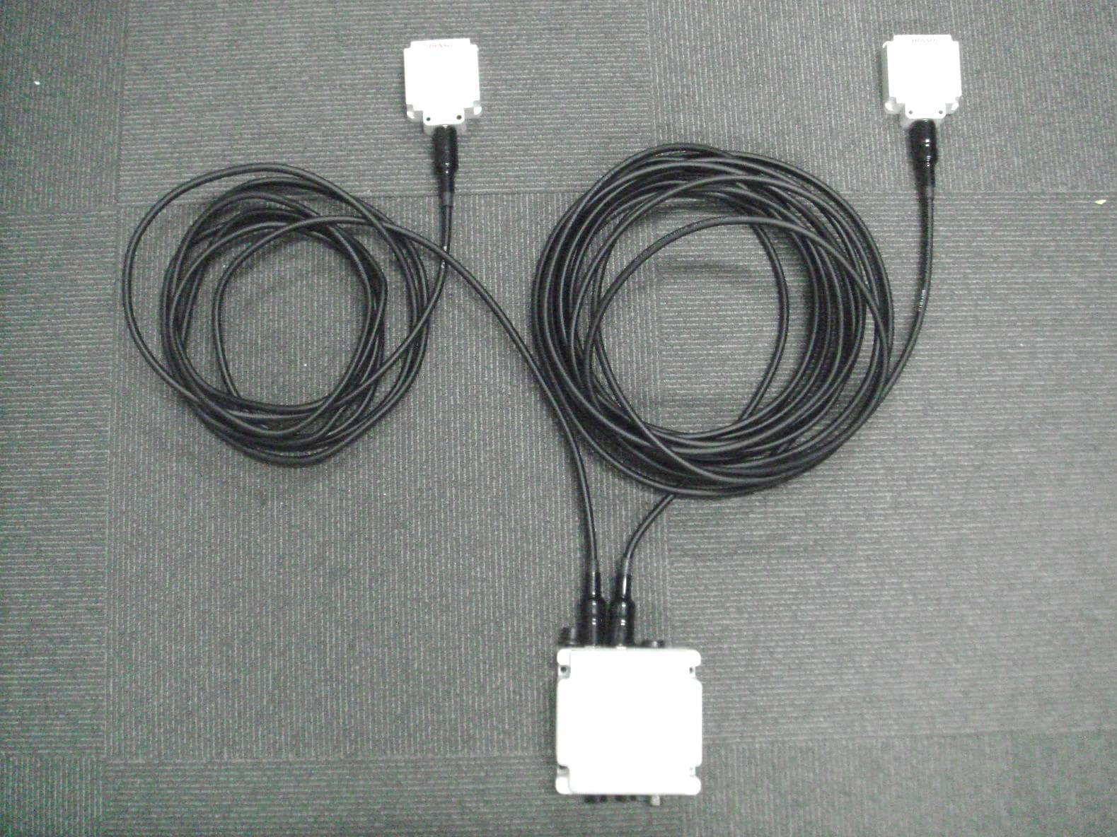
PZWUR50MERU
Jan 13, 2021Fixed Type RFID Scanner
Equipment Class
DSS - Part 15 Spread Spectrum Transmitter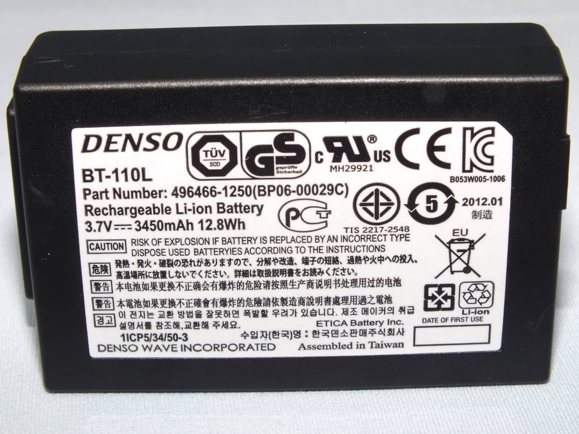
PZWBHT1200QU
Sep 21, 20152D Code Handy Terminal
Equipment Class
DSS - Part 15 Spread Spectrum Transmitter