PZWMI802B3Modular Spread Spectrum Transceiver
Denso Wave Incorporated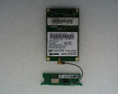
Click to zoom
Application Details
- Equipment Class
- DSS - Part 15 Spread Spectrum Transmitter
- Date of Grant
- Jul 17, 2002
- Application Purpose
- Original Equipment
- Date of Application
- Jul 17, 2002
- Equipment Note
- Modular Spread Spectrum Transceiver
- Frequency Range
- 2412.00000000 - 2462.00000000
- Company
- Denso Wave Incorporated
- Country
- Japan
Documents & Files
Document Text
Text extracted from the exhibit documents filed with the FCC. Open a document above to read the original.
Users Manual
24 User’s manual Operation manual Please refer to Attachment 9.1. User’s Manual Requirement of FCC rule MI802B3 is installed in Bar-code handy terminal, so MI802B3 has not manual for user. (Not sale only MI802B3 in US marketplace) FCC user’s manual requirements that are FCC rule Part 15.21 and 15.105 are described on user’s manual of Bar-code Handy terminal. Also SAR caution statement is described on user’s manual of Bar-code Handy terminal. (Please refer Fig 9.1) Fig 9.1 FCC rule requirement for user’s manual FCC and RSS-210 Regulations This device complies with Part 15of the FCC Rules and RSS-210 Rules Operation is subject to the following two conditions : (1) this device may not cause harmful interference, and (2) this device must accept any interference received, including interference that may cause undesired operation. FCC WARNING : Changes or modifications not expressly approved by the party responsible for compliance could void the user’s authority to operate the equipment. NOTE : This equipment has been tested and found to comply with the limits for a Class A digital device, pursuant to part 15 of the FCC Rules. These limits are designed to provide reasonable protection against harmful interference when the equipment is operated in a commercial environment. This equipment generates, uses, and can radiate radio frequency energy and, if not installed and used in accordance with the instruction manual, may cause harmful interference to radio communications. Operation of this equipment in a residential area is likely to cause harmful interference in which case the user will be required to correct the interference at his own expense. Caution : Radio Frequency Exposure This device is approved for hand held use only and, to comply with applicable FCC radio frequency exposure regulations, must be used with a distance of at least 20cm (7.9 inches) between the antenna and the body of any person at all time during use. ICES-003 Regulation This Class A digital apparatus complies with Canadian ICES-003. Cet appareil numérique de la classe A est conforme à la norme NMB-003 du Canada.
Cover Letter(s)
A- PEX INTERNATIONAL CO., LTD. •EMC HEAD OFFICE DIVISION•4383-326 Asama-cho, Ise-shi, Mie-ken 516-0021 Japan TEL:0596-24-8116/FAX:0596-24-8124 July 31, 2002 Re : DENSO WAVE INCORPORATED FCC ID : PZWMI802B3 Dear Mr. William H. Graff Please find the following replies to your comments dated June 30, 2002; 1) Radiated Emission measurement is carried out Stand Alone as LMA requested. Conducted Emission measurement is measured with integrating RF Module into Bar Code Handy Terminal for measuring accurate AC Conducted Noise when RF module recharge battery and emit radio wave at same time. Also, for FCC Part15B measurement, both Radiated and Conducted Emission are measured by using same and full system. 2) Antenna Gain is -3.86dBi for both Antenna A and B. 3) Please refer to submitted PDF "Operational Description for RF Module". 4) Please refer to submitted PDF "Test Report 21BE0027-YW-1". 5) Please refer to submitted PDF Data "Spurious data A11(22IE0091-YW). Keijiro Kumagai A-Pex International Co., Ltd.
Cover Letter(s)
American Telecommunications Certification Body Inc. 6731 Whittier Ave, McLean, VA 22101 June 30, 2002 RE: Denso Wave Incorporated FCC ID: PZWM802B3 I have thought very hard about this Application. However, there are still some items I must resolve before I complete my review 1) The Test Setup photos show in one photo, the hand held scanner in its cradle, while in another photo a device (the data receiver?) is attached to a computer. This is not correct. This Application is for a Limited Modular Approval of a specific radio inside a hand held scanner. The photos should show identical equipment for both Radiated Emissions and Powerline Conducted. Please review. 2) There are two antennas identified in the Antenna Specification. These will be the only ones authorized under this Application. Please provide antenna gain information for each antenna. 3) The Operational Description appears to be an extraction from a manual – possibly the scanner? It does not describe the module, and therefore is not appropriate for this Application. Please provide a detailed Operational Description of the RF module. 4) The Manual specifies this is a Class A digital device. Please provide evidence or attestation of testing to the Class A limits. In addition, the Test Report appears to show evidence of compliance with the Class B limits. This confuses the references in the Manual to the Class A limits. 5) The Radiated Band Edge emission data shows a peak approximately 18MHz above the 2483.5 MHz Band Edge. This emission falls within the Restricted Bands of 15.205. Please provide a field strength reading for this emission. Please provide a Peak and Average field strength reading for this emission. William H. Graff President and Examining Engineer mailto: [email protected] The items indicated above must be submitted before processing can continue on the above referenced application. Failure to provide the requested information may result in application termination. Correspondence should be considered part of the permanent submission and may be viewed from the Internet after a Grant of Equipment Authorization is issued. Please do not respond to this correspondence using the email reply button. In order for your response to be processed expeditiously, you must submit your documents through the AmericanTCB.com website. Also, please note that partial responses increase processing time and should not be submitted. Any questions about the content of this correspondence should be directed to the sender.
External Photos
Internal Photo Denso Wave Incorporated FCC ID: PZWMI802B3 Model Name: MI802B3 Front View of RF Module Back View of RF Module
ID Label/Location Info
22 Appearance and Marking Location Fig 8.1. Appearance (with RF shield) Top side Bottom side Location of FCC ID and IC ID label Top side Bottom side Fig 8.2. Appearance (without RF shield) 23 - Marking Layout on the RF module - Marking Layout and Location of Bar code reader TypeMI802B3 FCC IDPZWMI802B3 IC ID1551C-MI802B3 23.0±0.3 11.0±0.3 Unit : mm BHT-7500W Contains - FCC ID : PZWMI802B3 - IC ID : 1551C-MI802B3 THIS DEVICE COMPLIES WITH PART 15 OF THE FCC RULES. OPERATION IS SUBJECT TO THE FOLLOWING TWO CONDITIONS : (1) THIS DEVICE MAY NOT CAUSE HARMFUL INTERFERENCE, AND (2) THIS DEVICE MUST ACCEPT ANY INTERFERENCE RECEIVED, INCLUDING INTERFERENCE THAT MAY CAUSE UNDESIRED OPERATION.
Internal Photos
Internal Photo Denso Wave Incorporated FCC ID: PZWMI802B3 Model Name: MI802B3 Front View of RF Module Back View of RF Module Internal Photo Denso Wave Incorporated FCC ID: PZWMI802B3 Model Name: MI802B3 Front View of RF Module without Shield Back View of RF Module without Shield Internal Photo Denso Wave Incorporated FCC ID: PZWMI802B3 Model Name: MI802B3 Front View of Antenna Back View of Antenna
Operational Description
1 Product Outline This product is a Direct sequence spread-spectrum wireless network adapter. This product is installed in bar-code reader. And this product transmits data of bar-code to host computer. Product Specification - Manufacturer name : DENSO WAVE INCORPORATED - Address : 1-1 Showa-cho, Kariya-shi, Aichi-ken 448-8661 Japan - Product name : Micro ISA Wireless LAN Adapter - Product Type No. : MI802B3 - FCC ID : PZWMI802B3 - Frequency range : 2400MHz to 2483.5MHz - Operating Frequency : 2412 MHz to 2462MHz - Frequency Tolerance : 25 ppm - Modulation : Direct Sequence Spread-Spectrum - ITU emission code : 22M0G1D - Channels : 11ch - Cahnnel spacing : 5MHz (each) - RF Output power in Watts : 0.033 W - Nominal voltage : 3.30.16 VDC - Antenna type : External Antenna (Type A and Type B) *1 - Antenna gain : -3.86 dBi *1 : This product has two type antennas (Type A and Type B). The description of antenna is described on technical document of antenna.
Operational Description
Function of Wireless LAN adaptor (Model: MI802B3) incorporated in Bar- code Handy Terminal This Wireless LAN adopter is incorporated in Bar- code Handy Terminal. Basic functions of Wireless LAN adaptor are followings; 1. pro mptly send the data of scanned bar-code to host computer, 2. after storing the data of scanned bar-code in memory of Bar-code Handy Terminal at once time, send to the data of bar-code to host computer, 3. receive the information of bar-code from host computer. Specification of Wireless LAN Card (Model: MI802B3) The MI802B3 uses the 2.4GHz direct sequence spread spectrum technology as defined by the IEEE 802.11b Wireless LAN specification in order to accomplish real-time communication between a host computer or other device on a radio-based local area network. Direct sequence modulation provides secure, interference-immune communication and does not require a license for operation. The MI802B3 comes standard with Aironet enhancements to the 802.11b protocol which can be enabled to allow system optimizations which improve throughput and allow for more robust and reliable roaming. An all wireless LAN is the simplest LAN configuration. These configurations are also referred to as peer-to-peer or ad-hoc networks (802.11b uses the term IBSS – independent basic service set). In a ALL Wireless LAN, using a peer to peer network operating system (such as Windows Millenium, Windows 2000, Windows 98, Windows for Workgroup or Windows 95), all devices equipped with the MI802B can be linked together and communicate directly with each other.
RF Exposure Info
25 Antenna description Type of antenna : Type A Type B 26 Technical Description of Antenna (Type A) 27 Circuit diagram Connect to RF module 28 Component layout Component side Solder side Scale : Free 29 PCB layout Component side Solder side Scale : Free 30 Part list Part No. Part name Description ANT 1 Antenna Input Impedance : 50 Ω Frequency band : 2400MHz – 2497MHz Gain : -6dBd VSWR : 3.5 1 Connector Photograph 31 Technical Description of Antenna (Type B) 32 Circuit diagram Connect to RF module 33 Component layout Component side Solder side Scale : Free 34 PCB layout Component side Solder side Scale : Free 35 Parts list Part No. Part name Description ANT 1 Antenna Input Impedance : 50 Ω Frequency band : 2400MHz – 2497MHz Gain : -6dBd VSWR : 3.5 1 Connector DL 1 Diode BRPG1204W Photograph
RF Exposure Info
RF Exposure Statement No. : 22IE0091-YW-1 Applicant: DENSO WAVE INCORPORATED Type of Equipment : Micro ISA Wireless LAN Adaptor Model No.: MI802B3 FCC ID: PZWMI802B3 A-PEX International Co., Ltd. YOKOWA LAB. 108 Yokowa-cho, Ise-shi, Mie-ken 516-1106 JAPAN Telephone:int +81 596 39 1485 Facsimile: int +81 596 39 0232 Page 1 FCC Radiation Exposure Statement: DENSO WAVE INCORPORATED Model : MI802B3 complies with FCC radiation exposure requirement specified in the FCC Rules 15.247(b)(4). Notice in Installation Manual FCC Radiation Exposure Statement: This equipment complies with FCC radiation exposure limits set forth for an uncontrolled environment. This equipment should installed and operated with minimum distance 20cm between the radiator and your body (excluding extremities : hands, wrists, and feet) and must not be co-located or operated with any antenna or transmitter. RF Exposure Calculations: The following information provides the minimum separation distance for the highest gain antenna provided with the “MI802B3” as calculated from FCC OET 65 Appendix B, Table (B) Limits for General Population / Uncontrolled Exposure. This calculation is based on the highest EIRP possible from the system, considering maximum power and antenna gain, and considering a 1.0m W/cm^2 uncontrolled exposure limit. The Fires formula used was: S = (P * G) / (4* * r^2) or r = (P * G) / (4 * * S) Where S = 1.0 mW/cm^2 for 2400 MHz P = 38.9mW (Maximum Conducted Power) G = 0.41(Isotropic antenna gain : Converted absolute value) r = Minimum safe distance from antenna (cm) For: MI802B3 r = 1.13cm
RF Exposure Info
RF ModuleAntenna Board Brock Antenna
Test Report
A-PEX INTERNATIONAL CO., LTD. YOKOWA NO.3 OPEN SITE Company: DENSO WAVE INCORPORATEDReport No.: 22IE0091-YW-1 Equipment: Micro ISA Wireless LAN AdapterRegulation: FCC Part15C 247 / 205 & 209 Model: MI802B3Test Distance: 3m and 1m Sample No.: Date : 2002/05/19 FCC ID: PZWMI802B3Temperature: 22deg.C Power: DC 3.3VHumidity: 67% Mode: Transmitting (ch11: 2462MHz)Reviced Date : 2002/07/02 ENGINEER : Naoki Sakamoto AV DETECT(S/A : RBW 1MHz and VBW 10Hz) No.FREQS/A READINGANTAMPCABLEH-PassATTNDutyD-facRESULTLimitMARGIN HORVERFactorGAINLOSSFilterFactorHORVERAVHORVER [GHz][dB][dB][dB][dB][dB][dB][dB][dBuV/m] 12.4835040.439.731.638.03.00.010.0-0.047.046.354.07.07.7 22.4972142.240.731.638.03.00.010.0-0.048.847.354.05.26.7 34.9240036.835.335.837.94.51.10.0-0.040.338.854.013.715.2 47.3860032.332.639.238.35.60.50.0-0.039.339.654.014.714.4 59.8480034.334.239.238.56.70.50.0-0.042.242.154.011.811.9 612.3100033.433.343.338.57.50.50.0-9.536.736.654.017.317.4 714.7720032.432.642.938.58.30.50.0-9.536.136.354.017.917.7 817.2340034.634.438.738.58.60.60.0-9.534.534.354.019.519.7 919.6960035.634.838.038.510.31.50.0-9.537.436.654.016.617.4 1022.1580035.735.539.438.511.30.30.0-9.538.738.554.015.315.5 1124.6200035.635.539.138.612.30.90.0-9.539.839.754.014.214.3 PK DETECT(S/A : RBW 1MHz and VBW 1MHz) No.FREQS/A READINGANTAMPCABLEH-PassATTNDutyD-facRESULTLimitMARGIN HORVERFactorGAINLOSSFilterFactorHORVERPKHORVER [GHz][dB][dB][dB][dB][dB][dB][dB][dBuV/m] 12.4835051.750.631.638.03.00.010.0-0.058.357.274.015.716.8 22.4972149.949.631.638.03.00.010.0-0.056.556.274.017.517.8 34.9240050.246.535.837.94.51.10.0-0.053.750.074.020.324.0 47.3860043.944.139.238.35.60.50.0-0.050.951.174.023.122.9 59.8480045.444.839.238.56.70.50.0-0.053.352.774.020.721.3 612.3100045.345.043.338.57.50.50.0-9.548.648.374.025.425.7 714.7720044.544.242.938.58.30.50.0-9.548.247.974.025.826.1 817.2340046.345.838.738.58.60.60.0-9.546.245.774.027.828.3 919.6960046.746.738.038.510.31.50.0-9.548.548.574.025.525.5 1022.1580048.247.339.438.511.30.30.0-9.551.250.374.022.823.7 1124.6200047.246.539.138.612.30.90.0-9.551.450.774.022.623.3 REMARKS *Test Distance 1.0m : Distance Factor(D-fac) = 20log(3/1) = 9.5dB *Except for the above table : All other spurious emissions were less than 20dB for the limit. [dBuV/m] DATA OF SUPURIOUS EMISSIONS(1GHz to 26GHz) Page: A11 Test distance 1meters RESULT=Reading + ANT Factor - Amp Gain + CABLE LOSS + High Pass - Dfac [dB] [dB] Test distance 1meters RESULT=Reading + ANT Factor - Amp Gain + CABLE LOSS + High Pass - Dfac [dBuV][dBuV/m] Test distance 3meters RESULT=Reading + ANT Factor - Amp Gain + CABLE LOSS + (High Pass or ATTEN) Test distance 3meters RESULT=Reading + ANT Factor - Amp Gain + CABLE LOSS + (High Pass or ATTEN) [dBuV]
Test Setup Photos
Test report No. : 22IE0091-YW-1 Page: 15 of 17 Issued date: May 29, 2002 FCC ID: PZWMI802B3 A-pex International Co., Ltd. YOKOWA LAB. 108 Yokowa-cho, Ise-shi, Mie-ken 516-1106 JAPAN Telephone:int +81 596 39 1485 Facsimile: int +81 596 39 0232 Conducted emission Test report No. : 22IE0091-YW-1 Page: 16 of 17 Issued date: May 29, 2002 FCC ID: PZWMI802B3 A-pex International Co., Ltd. YOKOWA LAB. 108 Yokowa-cho, Ise-shi, Mie-ken 516-1106 JAPAN Telephone:int +81 596 39 1485 Facsimile: int +81 596 39 0232 Radiated emission
Contact Information
Applicant
Takehiko Koshino(Proj. Mgr, AUTO-ID Business Unit Eng. Plan.Div.)
Technical Contact
A-Pex International Co., Ltd.Naoki Sakamoto
[email protected]+81-596-39-1485
108 Yokowa-cho · Ise-Shi, Mie-ken · Japan
Non-Technical Contact
A-Pex International Co., Ltd.Kanako Sanda
[email protected]+81-596-24-8116
Test Firm
UL Japan, Inc.Kazunori Nishimura
Technical Specifications
| # | Rule Parts | Frequency Range | Power Output |
|---|---|---|---|
| 1 | 15C | 2.41 GHz - 2.46 GHz | 39.00 mW |
Other Applications from Denso Wave Incorporated
PZWSE1BUBC
Jan 17, 2024RF Tag Handy Scanner
Equipment Class
DSS - Part 15 Spread Spectrum Transmitter
PZWBHTM80QW
Feb 04, 20212D Code Handy Terminal
Equipment Class
DSS - Part 15 Spread Spectrum Transmitter
PZWBHTM80QWG
Jan 27, 20212D Code Handy Terminal
Equipment Class
NII - Unlicensed National Information Infrastructure TX
PZWUR50MERU
Jan 13, 2021Fixed Type RFID Scanner
Equipment Class
DSS - Part 15 Spread Spectrum Transmitter
PZWBHT1200QU
Sep 21, 20152D Code Handy Terminal
Equipment Class
DSS - Part 15 Spread Spectrum Transmitter