Q2331308Bluetooth EDR module
Intel Mobile Communications GmbH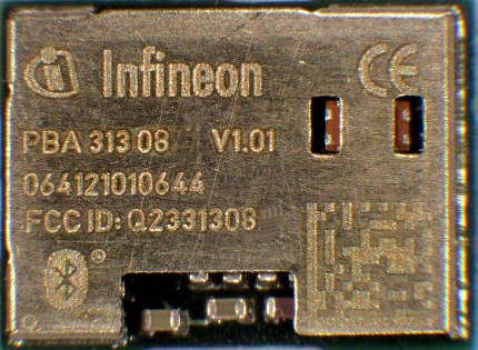
Click to zoom
Application Details
- Equipment Class
- DSS - Part 15 Spread Spectrum Transmitter
- Date of Grant
- Jan 11, 2007
- Application Purpose
- Original Equipment
- Date of Application
- Jan 11, 2007
- Equipment Note
- Bluetooth EDR module
- Frequency Range
- 2402.00000000 - 2480.00000000
- Country
- Germany
Documents & Files
Document Text
Text extracted from the exhibit documents filed with the FCC. Open a document above to read the original.
Users Manual
UniStone Important Application Information Product Specification208T3130-8XV10T4-7600, 2006-12-18 CONFIDENTIAL 9Important Application Information 9.1Reference design Figure 9-1Reference design schematics *n.p. means that the component is not mounted (i.e. not placed) UniStone Important Application Information Product Specification209T3130-8XV10T4-7600, 2006-12-18 CONFIDENTIAL PBA 31308 is intended to be installed inside an end user equipment. PBA 31308 is Bluetoooth, R&TTA and FCC qualified with the reference design described in Figure 9- 1 togheter with the following antenna: Manufacturers of mobile, fixed or portable devices incorporating this device are advised to clarify any regulatory questions and to have their complete product tested and approved for compliance (FCC or other when applicable). There are no parts in PBA 31308 that can be modified by the user except modifications of the device BD data and loading of SW patches. Any changes or modifications made to this device that are not expressly approved by Infineon, may void the user’s authority to operate the equipment. 9.2FCC Class B digital devices regulatory notice This equipment has been tested and found to comply with the limits for a Class B digital device, pursuant to Part 15 of the FCC Rules. These limits are designed to provide reasonable protection against harmful interference in a residential installation. This equipment generates, uses, and can radiate radio frequency energy and, if not installed and used in accordance with the instructions, may cause harmful interference to radio communications. However, there is no guarantee that interference will not occur in a particular installation. If this equipment does cause harmful interference to radio or television reception, which can be determined by turning the equipment off and on, the user is encouraged to try to correct the interference by 1 or more of the following measures: • Reorient or relocate the antenna • Increase the separation between the equipment and receiver • Connect the equipment into an outlet on a circuit different from that to which the receiver is connected • Consult the dealer or an experienced radio or television technician for help 9.3FCC Wireless notice This product emits radio frequency energy, but the radiated output power of this device is far below the FCC radio frequency exposure limits. Nevertheless, the device should be used in such a manner that the potential for human contact with the antenna during normal operation is minimized. To meet the FCC's RF exposure rules and regulations: MakeModelPeak antenna gain Impedance gigaAntTitanis4 - 4.4 dBi50 ohm UniStone Important Application Information Product Specification210T3130-8XV10T4-7600, 2006-12-18 CONFIDENTIAL • The system antenna(s) used for this transmitter must not be co-located or operating in conjunction with any other antenna or transmitter. • The system antenna(s) used for this module must not exceed 4 dBi. • Users and installers must be provided with antenna installation instructions and transmitter operating conditions for satisfying RF exposure compliance. Manufacturers of mobile, fixed or portable devices incorporating this module are advised to clarify any regulatory questions and to have their complete product tested and approved for FCC compliance. 9.4FCC Interference Statement This device complies with Part 15 of the FCC Rules. Operation is subject to the following two conditions: (1) this device may not cause harmful interference, and (2) this device must accept any interference received, including interference that may cause undesired operation. 9.5FCC Identifier FCC ID: Q2331308 9.6European R&TTE declaration of conformity Hereby, Infineon Technology AG, declares that the Bluetooth module PBA 31308 is in compliance with the essential requirements and other relevant provisions of Directive 1999/5/EC. As a result of the the conformity assessment procedure described in Annex III of the Directive 1999/5/EC, this equipment will be labelled as follows: PBA31308 in the specified reference design can be used in the following countries: Austria, belgium, Cyprus, Czech republic, Denmark Estonia, Finland, France, Germany, Greece, Hungary, Ireland, Italy, Latvia, Lithuania, Luxembourg, Malta, Poland, Portugal, Slovakia, Slovenia, Spain, Sweden, The Netherlands, United Kingdom, Switzerland, Norway, Iceland 0682 UniStone Important Application Information Product Specification211T3130-8XV10T4-7600, 2006-12-18 CONFIDENTIAL UniStone Important Application Information Product Specification212T3130-8XV10T4-7600, 2006-12-18 CONFIDENTIAL 9.7Industry Canada Certification PBA31308 comply with the regulatory requirements of Industry canada (IC), license: IC: 6850A-31308 Manufacturers of mobile, fixed or portable devices incorporating this module are advised to clarify any regulatory questions and ensure compliance for SAR and/or RF exposure limits. Users can obtain Canadian information on RF exposure and compliance from www.ic.gc.ca This device has been designed to operate with the antenna listed in section 8.1 above , having a maximum gain of 4.0 to 4.5 dBi. Antennas not included in this list or having a gain greater than 4.0 dB are strictly prohibited for use with this device. The required antenna impedance is 50 ohms. The antenna used for this transmitter must not be co- located or operating in conjunction with any other antenna or transmitter. 9.8Label design of the host product It is recommended to include the following information on the host product label: Contains transmitter Module FCC ID: Q2331308 / IC: 6850A-31308
Cover Letter(s)
MET Laboratories, Inc. 914 West Patapsco Avenue Baltimore, MD 21230-3432 Dec. 20, 2006 RE: 15.19 Statement (FCC ID: Q2331308) TO WHOM IT MAY CONCERN The statement: "This device complies with Part 15 of the FCC Rules. Operation is subject to the following two conditions: (1) this device may not cause harmful interference, and (2) this device must accept any interference received, including interference that may cause undesired operation” Is not placed in the label of the equipment due to the following reasons: - Type label is too small (No room for this writing). - Required text is already included in the user guide This statement is placed in a prominent location in the instruction manual. Please contact me if there is any information you may need. If you have any questions, please feel free to contact me at the address shown below. Sincerely, P.A. Mr. Johan Meivert Project Manager INFINEON TECHNOLOGIES AG Isafjordsgatan 16, Kista, SE-164 81, Sweden
Cover Letter(s)
attn: Reviewing Engineer MET Laboratories, Inc. 914 West Patapsco Avenue Baltimore, MD 21230-3432 RE: LETTER OF AGENT AUTHORIZATION Dec. 20, 2006 To Whom It May Concern: We, the undersigned, hereby authorize MET Laboratories, Inc. to act on our behalf in all matters relating to application for equipment authorizations (FCC ID: Q2331308), including the signing of all documents relating to these matters. We also hereby certify that no party to the application authorized hereunder is subject to the denial of benefits, including FCC benefits, pursuant to Section 5301 of the Anti-Drug Abuse Act of 1988,21 U.S.C.853(a). This agreement expires one year from the current date. Sincerely, P.A. Mr. Johan Meivert Project Manager INFINEON TECHNOLOGIES AG Isafjordsgatan 16, Kista, SE-164 81, Sweden
Cover Letter(s)
attn: Reviewing Engineer MET Laboratories, Inc. 914 West Patapsco Avenue Baltimore, MD 21230-3432 Dec 20, 2006 RE: Modular approval FCC ID: FCC ID: Q2331308 FCC ID Number Product Title/Model Q2331308 Bluetooth 2.0+EDR module / Model: PBA 313 08 INFINEON TECHNOLOGIES AG would like to have your authorization for Modular Approval specific to the mobile configurations for the product Bluetooth module PBA 313 08 with FCC ID: Q2331308 The requirements of Public Notice DA00-1407 have been met and shown on the following statements. 1. “The modular transmitter must have its own RF shielding.”: The radio portion of this module has been shielded, please see photographs provided with the application.. 2. “The modular transmitter must have buffered modulation/data inputs.”: The EUT has buffered data inputs, please refer to the operation description. 3. “The modular transmitter must have its own power supply regulation.”: The equipment has a voltage regulator, please refer to the schematics and the operational description. 4. “The modular transmitter must comply with the antenna requirements of section 15.203 and 15.204(C).”: The module meets the FCC antenna requirements, the device is designed to be operated with an specific antenna. Please refer to the user’s manual and operational description. 5. “The modular transmitter must be tested in a stand-alone configuration”: The equipment was tested in a stand-alone configuration via a serial cable. Please see section test setup photographs submitted with the application. 6. “The modular transmitter must be labeled with its own FCC ID number.”: The module is labelled with its own FCC ID number, please see product label design and the external photograph of the device with this label submitted with the application. 7. “The modular transmitter must comply with any specific rule or operating requirements applicable to the transmitter and the manufacturer must provide adequate instructions along with the module to explain any such requirements.”: The equipment is compliant with all applicable FCC rules. Detail instructions for maintaining compliance are given in the Users Manual. 8. “The modular transmitter must comply with any applicable RF exposure requirements.”: The device is compliant with all applicable RF exposure requirements. RF Exposure is addressed in the RF exposure information. Sincerely, P.A. Mr. Johan Meivert Project Manager INFINEON TECHNOLOGIES AG Isafjordsgatan 16, Kista, SE-164 81, Sweden
Cover Letter(s)
MET Laboratories, Inc. 914 West Patapsco Avenue Baltimore, MD 21230-3432 Dec. 20, 2006 TO WHOM IT MAY CONCERN Pursuant to Paragraphs §0.457 and 0.459 of the Commission’s Rules (47 C.F.R.) and Section §552(b)(4) of the Freedom of Information Act, INFINEON TECHNOLOGIES AG requests confidentiality for the following products: FCC ID Number Product Title/Model Q2331308 Bluetooth 2.0+EDR module / Model: PBA 313 08 For the product stated above, we request that the following information be held confidential: 1) Circuit diagrams 2) Block Diagrams 3) Bill of materials 4) Operational Description No other items submitted as part of the equipment authorization filing process are deemed confidential. The above exhibits contain INFINEON TECHNOLOGIES AG trade secrets and proprietary information that could be of benefit to our competitors. This material is not customarily available to the general public and we request that it be withheld from public inspection. If you have any questions, please feel free to contact me at the address shown below. Sincerely, Name: Johan Meivert P.A. Date: Dec. 20, 2006 Place: Kista Signature and company stamp
ID Label/Location Info
UniStone Package Information Product Specification206T3130-8XV10T4-7600, 2006-12-18 CONFIDENTIAL 8Package Information 8.1Package marking PBA 31308 V1.01 FCC ID: Q2331308 G0644 5N605001 Date code FCC ID Version Machine readable 2D date code
Internal Photos
Richard Wallace IFND COM PS CSE AE UniStone October 2006 Page 1 UnistoneDesign Inside Unistone
RF Exposure Info
Attn: Reviewing Engineer MET Laboratories, Inc. 914 West Patapsco Avenue Baltimore, MD 21230-3432 Dec. 20, 2005 RE: RF exposure information FCC ID: Q2331308 FCC ID Number Product Title / Model Q2331308 Bluetooth 2.0+EDR module / Model: PBA 313 08 TO WHOM IT MAY CONCERN The product stated above complies with the FCC limits for Human exposure to RF emissions. This device is categorically excluded from routine environmental, because it operates at very low power level. The equipment is deemed to comply with the SAR or MPE limits without testing due to its very low power level (EIRP < 2.5 mW). Sincerely, P.A. Mr. Johan Meivert Project Manager INFINEON TECHNOLOGIES AG Isafjordsgatan 16, Kista, SE-164 81, Sweden Phone: +46 8 757 50 00 E-mail: [email protected]
Test Report
Report No.: 24838RET.101 Date: 2006-12-13 Page: 2 of 8 FDT08_04 INDEX 1. COMPETENCE AND GUARANTEES..........................................................................................3 2. GENERAL CONDITIONS..............................................................................................................3 3. CHARACTERISTICS OF THE TEST............................................................................................3 3.1 TEST REQUESTED.................................................................................................................3 3.2 REQUIREMENTS AND METHOD........................................................................................4 4. IDENTIFICATION DATA SUPPLIED BY THE APPLICANT.....................................................4 4.1 APPLICANT.............................................................................................................................5 4.2 REPRESENTATIVE................................................................................................................5 4.3 TEST SAMPLES SUPPLIER...................................................................................................5 4.4 IDENTIFICATION OF ITEM/ITEMS TESTED.....................................................................5 5. USAGE OF SAMPLES, PERIOD OF TESTING AND ENVIRONMENTAL CONDITIONS.....5 5.1 USAGE OF SAMPLES............................................................................................................5 5.2 PERIOD OF TESTING............................................................................................................6 5.3 ENVIROMENTAL CONDITIONS..........................................................................................7 6. TEST RESULTS..............................................................................................................................8 7. REMARKS AND COMMENTS......................................................................................................8 8. SUMMARY......................................................................................................................................8 ANNEXES ANNEX A. TEST RESULTS ANNEX B. MEASURING RESULTS FOR ELECTROMAGNETIC EMISSION ANNEX B. PHOTOGRAPHS Report No.: 24838RET.101 Date: 2006-12-13 Page: 3 of 8 FDT08_04 1. COMPETENCE AND GUARANTEES Centro de Tecnología de las Comunicaciones (AT4 WIRELESS), S.A. is a laboratory with a measurement facility in compliance with the requirements of Section 2.948 of the FCC rules and has been added to the list of facilities whose measurements data will be accepted in conjuction with applications for Certification under Parts 15 or 18 of the Commission's Rules. Registration Number: 905266. Centro de Tecnología de las Comunicaciones (AT4 WIRELESS), S.A. is a laboratory with a measurement site in compliance with the requirements of RSS 212, Issue 1 (Provisional) and has been added to the list of filed sites of the Canadian Certification and Engineering Bureau. Reference File Number: IC 4621. In order to assure the traceability to other national and international laboratories, AT4 WIRELESS has a calibration and maintenance programme for its measuring equipment. AT4 WIRELESS guarantees the reliability of the data presented in this report, which is the result of measurements and tests performed to the item under test on the date and under the conditions stated on the report and is based on the knowledge and technical facilities available at AT4 WIRELESS at the time of execution of the test. AT4 WIRELESS is liable to the client for the maintenance by its personnel of the confidentiality of all information related to the item under test and the results of the test. 2. GENERAL CONDITIONS 1. This report only refers to the item that has undergone the test. 2. This report does not constitute or imply by its own an approval of the product by the Certification Bodies or competent Authorities. 3. This document is only valid if complete; no partial reproduction can be made without written approval of AT4 WIRELESS. 4. This test report cannot be used partially or in full for publicity and/or promotional purposes without previous written approval of AT4 WIRELESS and the Accreditation Bodies. 3. CHARACTERISTICS OF THE TEST 3.1 TEST REQUESTED 1. Measurements for frequency hopping spread spectrum equipment (Bluetooth) operating in the 2400 MHz -2483.5 MHz band and using, according to FCC Part 15.247. 2. Continuous conducted emission, power leads: Standard: FCC Rules and Regulations 47 CFR Part 15 Limit: Class B Method: FCC Rules and Regulations 47 CFR Part 15, Subpart C Report No.: 24838RET.101 Date: 2006-12-13 Page: 4 of 8 FDT08_04 3.2 REQUIREMENTS AND METHOD 1. FCC parts 15.33, 15.35, 15.247, 15.207, 15.205, 15.209, 15.109 and the document DA 00- 705:"Filing and Measurement Guidelines for Frequency Hopping Spread Spectrum Systems". The testing was performed according to the procedure in ANSI C63.4: 2003. Radiated testing was performed in AT4 WIRELESS' semi-anechoic chamber. This site has been fully described in a report submitted to the FCC and was accepted in a letter dated July 25, 2002. 2. FCC Rules and Regulations 47 CFR Part 15, Subpart C: Limits and methods of measurements for radio frequency devices. Intentional radiators. The instrumentation used to perform the testing is listed below: 1. Semianechoic Absorber Lined Chamber IR 11. BS. 2. Control Chamber IR 12.BC. 3. Antenna mast EM 1072 NMT. 4. Rotating table EM 1084-4. ON. 5. Multi device controller ETS 2090. 6. Bilog antenna CHASE CBL6111. 7. Antenna tripod EMCO 11968C. 8. Double-ridge Guide Horn antenna 1-18 GHz HP 11966E. 9. Double-ridge Guide Horn antenna 18-40 GHz Agilent 119665J. 10. RF pre-amplifier Miteq JS4-12002600-30-5A. 11. Semianechoic Absorber Lined Chamber IR 11. BS. 12. RF pre-amplifier Miteq AFS5-04001300-15-10P-6. 13. RF pre-amplifier Schaffner CPA 9231. 14. Spectrum analyzer R&S ESIB 26. 15. Spectru…
Text truncated - open the document above for the full version.
Test Report
Report No: 24838RET.101 Date: 2006-12-13 Page: 34 of 61 Annex A FET45_00.DOC PEAK OUTPUT POWER (RADIATED). Modulation: GFSK Highest Channel: 2480 MHz. Modulation: Π/4-DQPSK Lowest Channel: 2402 MHz. Report No: 24838RET.101 Date: 2006-12-13 Page: 35 of 61 Annex A FET45_00.DOC PEAK OUTPUT POWER (RADIATED). Modulation: Π/4-DQPSK Middle Channel: 2441 MHz. PEAK OUTPUT POWER (RADIATED). Modulation: Π/4-DQPSK Highest Channel: 2480 MHz. Report No: 24838RET.101 Date: 2006-12-13 Page: 36 of 61 Annex A FET45_00.DOC PEAK OUTPUT POWER (RADIATED). Modulation: 8-DPSK Lowest Channel: 2402 MHz. Modulation: 8-DPSK Middle Channel: 2441 MHz. Report No: 24838RET.101 Date: 2006-12-13 Page: 37 of 61 Annex A FET45_00.DOC PEAK OUTPUT POWER (RADIATED). Modulation: 8-DPSK Highest Channel: 2480 MHz. Report No: 24838RET.101 Date: 2006-12-13 Page: 38 of 61 Annex A FET45_00.DOC Section 15.247 Subclause (d). Band-edge of conducted emissions (Transmitter) SPECIFICATION Emissions outside the frequency band in which the intentional radiator is operating shall be at least 20dB below the highest level of the desired power. RESULTS: Modulation: GFSK 1. LOW FREQUENCY SECTION 2402 MHz (HOPPING OFF). See next plot. Verdict: PASS Report No: 24838RET.101 Date: 2006-12-13 Page: 39 of 61 Annex A FET45_00.DOC 2. HIGH FREQUENCY SECTION 2480 MHz (HOPPING OFF). See next plot. Verdict: PASS 3. LOW FREQUENCY SECTION (HOPPING ON). See next plot. Verdict: PASS Report No: 24838RET.101 Date: 2006-12-13 Page: 40 of 61 Annex A FET45_00.DOC 4. HIGH FREQUENCY SECTION (HOPPING ON). See next plot. Verdict: PASS Report No: 24838RET.101 Date: 2006-12-13 Page: 41 of 61 Annex A FET45_00.DOC Modulation: Π/4-DQPSK 1. LOW FREQUENCY SECTION 2402 MHz (HOPPING OFF). See next plot. Verdict: PASS 2. HIGH FREQUENCY SECTION 2480 MHz (HOPPING OFF). See next plot. Verdict: PASS Report No: 24838RET.101 Date: 2006-12-13 Page: 42 of 61 Annex A FET45_00.DOC 3. LOW FREQUENCY SECTION (HOPPING ON). See next plot. Verdict: PASS 4. HIGH FREQUENCY SECTION (HOPPING ON). See next plot. Verdict: PASS Report No: 24838RET.101 Date: 2006-12-13 Page: 43 of 61 Annex A FET45_00.DOC Modulation: 8-DPSK 1. LOW FREQUENCY SECTION 2402 MHz (HOPPING OFF). See next plot. Verdict: PASS 2. HIGH FREQUENCY SECTION 2480 MHz (HOPPING OFF). See next plot. Verdict: PASS Report No: 24838RET.101 Date: 2006-12-13 Page: 44 of 61 Annex A FET45_00.DOC 3. LOW FREQUENCY SECTION (HOPPING ON). See next plot. Verdict: PASS 4. HIGH FREQUENCY SECTION (HOPPING ON). See next plot. Verdict: PASS Report No: 24838RET.101 Date: 2006-12-13 Page: 45 of 61 Annex A FET45_00.DOC Section 15.247 Subclause (d). Emission limitations conducted (Transmitter) SPECIFICATION In any 100 kHz bandwidths outside the frequency band in which the intentional radiator is operating, the radio frequency power that is produced by the intentional radiator shall be at least 20dB below that in the 100 kHz bandwidth within the band that contains the highest level of the desired power. RESULTS: Modulation: GFSK 1. LOWEST CHANNEL (2402 MHz): 30 MHz-25 GHz (see next plot). Note: The peak above the limit is the carrier frequency. Verdict: PASS Report No: 24838RET.101 Date: 2006-12-13 Page: 46 of 61 Annex A FET45_00.DOC 2. MIDDLE CHANNEL (2441 MHz): 30 MHz-25 GHz (see next plot). Note: The peak above the limits is the carrier frequency. Verdict: PASS 3. HIGH CHANNEL (2480 MHz): 30 MHz-25 GHz (see next plot). Note: The peak above the limits is the carrier frequency. Verdict: PASS Report No: 24838RET.101 Date: 2006-12-13 Page: 47 of 61 Annex A FET45_00.DOC Modulation: Π/4-DQPSK 1. LOWEST CHANNEL (2402 MHz): 30 MHz-25 GHz (see next plot). Note: The peak above the limits is the carrier frequency. Verdict: PASS 2. MIDDLE CHANNEL (2441 MHz): 30 MHz-25 GHz (see next plot). Note: The peaks above the limits are the carrier frequencies. Verdict: PASS Report No: 24838RET.101 Date: 2006-12-13 Page: 48 of 61 Annex A FET45_00.DOC 3. HIGH CHANNEL (2480 MHz): 30 MHz-25 GHz (see next plot). Note: The peak above the limit is the carrier frequency. Verdict: PASS Report No: 24838RET.101 Date: 2006-12-13 Page: 49 of 61 Annex A FET45_00.DOC Modulation: 8-DPSK 1. LOWEST CHANNEL (2402 MHz): 30 MHz-25 GHz (see next plot). Note: The peak above the limits is the carrier frequency. Verdict: PASS 2. MIDDLE CHANNEL (2441 MHz): 30 MHz-25 GHz (see next plot). Note: The peaks above the limit are the carrier frequencies. Verdict: PASS Report No: 24838RET.101 Date: 2006-12-13 Page: 50 of 61 Annex A FET45_00.DOC 3. HIGH CHANNEL (2480 MHz): 30 MHz-25 GHz (see next plot). Note: The peak above the limit is the carrier frequency. Verdict: PASS Report No: 24838RET.101 Date: 2006-12-13 Page: 51 of 61 Annex A FET45_00.DOC Section 15.247 Subclause (d). Emission limitations radiated (Transmitter) SPECIFICATION Radiated emissions which fall in the restricted bands, as defined in §15.205(a), must also comply with the radiated emission limits specified in §15.209(a) (see §15.205(c)): Frequency Range (MHz) Field strength (μV/m) Field strength (dBμV/m) Measurement distance (m) 0.009-0.490 2400/F(kHz) - 300 0.490-1.705 24000/F(kHz) - 300 1.705 - 30.0 30 - 30 30 - 88 100 40 3 88 - 216 150 43.5 3 216 - 960 200 46 3 960 - 25000 500 54 3 The emission limits shown in the above table are based on measurements employing CISPR quasi-peak detector except for the frequency bands 9-90 kHz, 110-490 kHz and above 1000 MHz. Radiated emission limits in these three bands are based on measurements employing an average detector. For average radiated emission measurements above 1000 MHz, there is also a limit corresponding to 20 dB above the indicated values in the table is specified when measuring with peak detector function. RESULTS: The orientation of the equipment under test was varied to find the maximum radiated emission. It was also rotated 360º and the antenna height was varied from 1 to 4 meters to find the maximum radiated emission. Measurements were made in both horizontal and vertical planes of polarizatio…
Text truncated - open the document above for the full version.
Test Setup Photos
Report No.: 24838RET.101 Date: 2006-12-13 Page: 2 of 8 Annex C FET18_00.DOC 1. Equipment for radiated measurements with the evaluation board (front view) Report No.: 24838RET.101 Date: 2006-12-13 Page: 3 of 8 Annex C FET18_00.DOC 2. Equipment for conducted measurements with the evaluation board (front view) Report No.: 24838RET.101 Date: 2006-12-13 Page: 4 of 8 Annex C FET18_00.DOC 3. Equipment with the evaluation board (back view) Report No.: 24838RET.101 Date: 2006-12-13 Page: 5 of 8 Annex C FET18_00.DOC 4. General test set-up for radiated measurements. Report No.: 24838RET.101 Date: 2006-12-13 Page: 6 of 8 Annex C FET18_00.DOC 5. Test set-up for radiated measurements below 1 GHz. Report No.: 24838RET.101 Date: 2006-12-13 Page: 7 of 8 Annex C FET18_00.DOC 6. Test set-up for radiated measurements above 1 GHz. Report No.: 24838RET.101 Date: 2006-12-13 Page: 8 of 8 Annex C FET18_00.DOC 7. Test set-up for RF conducted measurements.
Contact Information
Applicant
Steffen Buch(Program Manager Mobile Connectivity)
Test Firm
DEKRA Testing and Certification, S.A.U.Rafael Lopez Martin
Technical Specifications
| # | Rule Parts | Frequency Range | Power Output |
|---|---|---|---|
| 1 | 15C | 2.40 GHz - 2.48 GHz | 1.22 mW |
Other Applications from Intel Mobile Communications GmbH
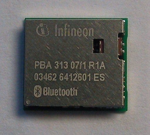
Q2331307
May 03, 2004Wireless Bluetooth module
Equipment Class
DSS - Part 15 Spread Spectrum Transmitter
Q23104001
Jun 17, 2003Wireless Bluetooth module
Equipment Class
DSS - Part 15 Spread Spectrum Transmitter