Q2U-GT69000FGSM 1900MHz GPS Device W/Beacon Technology
GeoTrax Protection LLC
Click to zoom
Application Details
- Equipment Class
- TNB - Licensed Non-Broadcast Station Transmitter
- Date of Grant
- Feb 11, 2004
- Application Purpose
- Original Equipment
- Date of Application
- Feb 09, 2004
- Equipment Note
- GSM 1900MHz GPS Device W/Beacon Technology
- Frequency Range
- 217.00000000 - 220.00000000
- Company
- GeoTrax Protection LLC
- Country
- United States
Documents & Files
Document Text
Text extracted from the exhibit documents filed with the FCC. Open a document above to read the original.
Users Manual
Global Pursuit Systems is one of the USCPC Group of Companies BLOODHOUND CASH TRACKER USER GUIDE Rev. July 2003 Global Pursuit Systems is one of the USCPC Group of Companies PRODUCT DESCRIPTION The BloodHound is the most advanced product available for the covert tracking of stolen cash. It encompasses multiple technologies to provide the user with the most capable means of locating currency after it is stolen. The technologies included are (1) a Global Positioning Satellite (GPS) receiver, (2) a cellular telephone modem and (3) a radio frequency (RF) transmitter. Each of these technologies require the proper handling and care of the device. QUESTIONS & SERVICE Should you have any questions regarding the BloodHound or feel you need service, please contact us at the following: USCPC/Global Pursuit Systems 16611 E. Laser Drive Fountain Hills, AZ 85268 Tel: (480) 837-3773 Fax: (480) 837-3774 DEVICE HANDLING First and foremost, it is important to realize that this device is an electronic assembly. While it was designed and constructed to withstand the proper handling and use without damaging the unit, improper handling of the device may damage the device and render it useless. The device should be handled with care. Please do not drop the device or try to bend the device to see how flexible it is. However, you should feel very confident that you can handle the device as you would any electronic device. Normal transport of the device between cash drawers, if necessary, can be done without damaging the device. As the device contains transmitted radio frequency waves, caution should be used when handling the device near the body and in particular near the head. However, be advised that the device uses commercially available radio frequency assemblies that have been shielded and the device has received the certification from the FCC that under the intended use of the product, the device will not cause any personal harm. Global Pursuit Systems is one of the USCPC Group of Companies USING THE DEVICE The BloodHound looks and feels like a stack of 100 bank notes. It is designed to be placed in a cash drawer and remain in the drawer until needed and used in a robbery situation. One of the most critical components to the device functionality is the battery -- as it is needed to power the device. The device incorporates a magnetic reed switch to keep the device in an off/dormant position as long as the device remains on the provided magnetic base. Therefore, the device should always remain on the magnetic base unless being used in a robbery. Using the device when needed in a robbery is very simple. If you experience a robbery situation and you are going to give the criminal the money in your cash drawer then please remember the following: 1. Follow your normal robbery procedures! 2. To minimize the likelihood of the bank robber detecting the BloodHound the device should be, if possible, surrounded with the other bills from the drawer 3. Hand the entire stack of money and the BloodHound to the perpetrator or place it in a bag if provided. Avoid trying to pass the BloodHound to the perpetrator as a stand-alone item as the detection of the device is probably likely in this scenario. 4. The BloodHound requires no special intervention by the user! There are no special buttons to push, as the device will activate once it is removed from the magnetic plate. CAUTIONS & REMINDERS The success of the device is determined by the condition of the device when it is used. In particular, the battery must have sufficient power to run the device. Please handle the device with care and keep it in the cash drawer and on the magnetic plate at all times. There are no user serviceable components and no need for anyone other than a qualified technician to service the device. The BloodHound does not know if the person carrying it is a bank employee or a bank robber. If the device needs to be removed from the teller drawer for any reason other than during a robbery, such as changing the band around the bills, then it is crucial that it only be removed for a few seconds at a time. If the device is off of the magnetic plate for more than 10 seconds, it will notify law enforcement personnel that a bank robbery is in process. To minimize the incidence of false alarms, an additional magnetic plate will be supplied to the bank branches. If you need to remove the device from the drawer, immediately place it on the additional magnetic plate. When you are ready to place the device back into the drawer, be sure to place it back on the magnetic plate in the drawer within a few seconds.
Cover Letter(s)
-----Original Message----- From: Claire Hoque Sent: Monday, February 09, 2004 6:42 PM To: Chris Harvey Cc: Thu Chan; '[email protected]' Subject: RE: AN04T3633 informal request. Hi Chris, Here are the answers for Geotrax project. (1) Emission Designator is 2K89GXW. (2) MPE calculation is attached. Pls issue the grant ASAP. Thanks, Claire From: Steve Cheng Sent: Thursday, February 05, 2004 1:08 PM To: Thu Chan Cc: Chris Harvey Subject: RE: AN04T3633 informal request. Thu, please provide the justification why you use 2K17GXW on the 731 form. The 26dB BW on the report is 2K89. Thanks. Steve, Although this device has very low power (0.0002 Watts ERP) , please provide a RF Exposure Complianbce information per 90.1217: Applications for equipment authorization of mobile or portable devices operating under this section must contain a statement confirming compliance with these requirements for both fundamental emissions and unwanted emissions. Additionally, please provide an Emission Designator with an explanation/justification of the selection of characters/numbers (the 2K17GXW on the Form 731 does not seem correct and is not explained in the application). The items indicated above must be submitted before processing can continue on the above referenced application. Failure to provide the requested information within 30 days of the original e-mail date may result in application dismissal and forfeiture of the filing fee. Also, please note that partial responses increase processing time and should not be submitted. Any questions about the content of this correspondence should be directed to the e-mail address listed below the name of the sender. Best regards, Chris Harvey [email protected]
ID Label/Location Info
PROPOSED FCC ID LABEL AND LOCATION GEOTRAX PROTECTION LLC FCC ID: Q2U-GT69000F FCC ID LABEL LOCATION
Parts List/Tune Up Info
Appendix A: Turn-Up and Acceptance Procedure Assembly Work Instructions Tuesday, April 15, 2003 1 Step 1: Attach Battery Assy. to Mother Board Assy using Kapton Tape on both sides of the Battery. Mother Board is attached on middle of the Battery. Carefully place exact length ofKapton Tape. Battery Wires are routed behind the Mother board and soldered on back of the Board. Assembly Work Instructions Tuesday, April 15, 2003 2 Step 2: Solder Battery Assy wires (R ed and Black) on back of the Board. Battery Assy. is secured to the Mother Board using Kapton Tape. Carefully place the exact length of Kapton Tape. Battery Wires are soldered on back of the Board. Shrink Tube is not required. Wires should not pass over IC. Assembly Work Instructions Tuesday, April 15, 2003 3 Step 3: Perform a Power Test. Turn the power ON using switch SW1. Verify LED D1 turns ON. Upon ve rification, turn the power OFF. Switch SW1. LED, D1. Connector for Antenna Assy. Assembly Work Instructions Tuesday, April 15, 2003 4 Antenna Assy. is secured to the Battery Assy using double sided sticky tape. Step 4: Install Antenna Assy to Mother Board Assy by removing double sided tape cover and placing it onto the Battery. Make sure Antenna board with LNA PCB is aligned to top edge of the Battery. Step 5: Make a loop on Coax cable a nd install Leadtek module on 20 pin connector on the Mother Board. Carefully make loop of Coax cable. LeadtekModule. Top Edge of the Battery. Before making a Loop.
RF Exposure Info
GEOTRAX PROJECT: 03U2055-1 MPE CALCULATION Formula used in the MPE Calculations: E^2/3770 = S, mW/cm2 Pwatts*Ggain = 10^(PdBm-30+GdBi)/10) E, V/m = (Pwatts*Ggain*30)^.5/d, meters d = ((Pwatts*G*30)/3770*S))^0.5 --------- (A) Since S (mW/cm2) = 0.2 from 1.1310 Table 1 P (dBm) = -6.4 EUT ERP output power G (dBi) = 2.15 EUT antenna gain Substitute these parameters into the A above, we have MPE safe distance d (cm) = 0.4 cm NOTE: For mobile or fixed location transmitters, minimum separation distance is 20 cm, even if calculations indicate MPE distance is less
Test Report
. FCC CFR47 PART 90 REQUIREMENT CERTIFICATION REPORT FOR GSM PCS1900 MHz SELF-CONTAINED GPS DEVICE WITH BEACON TECHNOLOGY MODEL: GT69000F FCC ID: Q2U-GT69000F REPORT NUMBER: 03U2055-1 ISSUE DATE: JUNUARY 23, 2004 Prepared for GEOTRAX PROTECTION LLC PO BOX 6021 SCTTSDALE, AZ 85261 Prepared by COMPLIANCE CERTIFICATION SERVICES 561F MONTEREY ROAD, MORGAN HILL, CA 95037, USA TEL: (408) 463-0885 FAX: (408) 463-0888 REPORT NO: 03U2055-1 DATE: JANUARY 23,2004 FCC ID: Q2U-GT69000F EUT: SELF-CONTAINED RADIO BEACON DEVICE Page 2 of 29 COMPLIANCE CERTIFICATION SERVICES DOCUMENT NO: CCSUP4031C 561F MONTEREY ROAD, MORGAN HILL, CA 95037 USA TEL: (408) 463-0885 FAX: (408) 463-0888 This report shall not be reproduced except in full, without the written approval of CCS. This document may be altered or revised by Compliance Certification Services personnel only, and shall be noted in the revision section of the document. TABLE OF CONTENTS 1. VERIFICATION OF COMPLIANCE...........................................................................3 1.1. PRODUCT DESCRIPTION......................................................................................4 1.2. METHODOLOGY.....................................................................................................4 1.3. TEST FACILITY.......................................................................................................4 1.4. ACCREDITATION AND LISTING.........................................................................4 1.5. MEASURING INSTRUMENT CALIBRATION.....................................................4 2. REQUIREMENTS OF PROVISION.............................................................................5 2.1. GENERAL TECHNICAL REQUIMENTS...............................................................5 2.2. LABELING REQUIREMENT..................................................................................5 2.3. USER INFORMATION.............................................................................................5 3. OUTPUT POWER MEASUREMENT..........................................................................6 3.1. PROVISION APPLICABLE......................................................................................6 3.2. MEASUREMENT METHOD....................................................................................6 3.3. MEASUREMENT INSTRUMENT.........................................................................10 3.4. MEASUREMENT RESULT....................................................................................10 4. MODULATION CHARACTERISTICS......................................................................11 5. EMISSION BANDWIDTH............................................................................................11 5.1. PROVISIONS APPLICABLE.................................................................................11 5.2. MEASUREMENT METHOD..................................................................................11 5.3. MEASUREMENT INSTRUMENT.........................................................................12 5.4. MEASUREMENT RESULT....................................................................................12 6. FIELD STRENGTH OF SPURIOUS EMISSION......................................................16 6.1. PROVISIONS APPLICABLE.................................................................................16 6.2. MEASUREMENT METHOD..................................................................................16 6.3. MEASUREMENT INSTRUMENT.........................................................................18 6.4. MEASUREMENT RESULT....................................................................................21 7. FREQUENCY STABILITY MEASUREMENT.........................................................26 7.1. PROVISIONS APPLICABLE.................................................................................26 7.2. MEASUREMENT METHOD..................................................................................26 7.3. MEASUREMENT INSTRUMENT.........................................................................28 7.4. MEASUREMENT RESULT....................................................................................28 8. TRANSIENT FREQUENCY BEHAVIOR..................................................................29 9. APPENDIX.....................................................................................................................29 REPORT NO: 03U2055-1 DATE: JANUARY 23,2004 FCC ID: Q2U-GT69000F EUT: SELF-CONTAINED RADIO BEACON DEVICE Page 3 of 29 COMPLIANCE CERTIFICATION SERVICES DOCUMENT NO: CCSUP4031C 561F MONTEREY ROAD, MORGAN HILL, CA 95037 USA TEL: (408) 463-0885 FAX: (408) 463-0888 This report shall not be reproduced except in full, without the written approval of CCS. This document may be altered or revised by Compliance Certification Services personnel only, and shall be noted in the revision section of the document. 1. VERIFICATION OF COMPLIANCE Inspection Institution: COMPLIANCE CERTIFICATION SERVICES 561F MONTEREY ROAD, MORGAN HILL, CA 95037, USA TEL: (408) 463-0885 FAX: (604) 463-0888 Applicant: GEOTRAX PROTECTION LLC Manufacturer: GEOTRAX PROTECTION LLC Brand Name: Cash Tracker with Beacon Tracking Model No/Name: GT69000F/ GSM PCS1900 MHz Self-contained GPS Device with Beacon Technology ITEM TESTING ITEM APPLIED SPECIFICATION TESTING RESULTS TESTING EQUIPMENT REMARK 1 Type acceptance required Section 90.203 Complied Note 1 2 Power and Antenna Height Limits Section 90.205 Complied Note 1 3 Types of Emissions Section 90.207 Complied Note 1 4 Emission Bandwidth Section 90.209 Complied Note 1 5 Unwanted Emission Section 90.210 Complied Note 1 6 Frequency Stability Section 90.213 Complied Note 1 Note 1: Please refer to each test section for detailed instrument list. The above equipment was tested by Compliance Certification Services for compliance with the requirements set forth in the FCC PART 90. The r…
Text truncated - open the document above for the full version.
Test Setup Photos
REPORT NO: 03U2055-1 DATE: JANUARY 23,2004 FCC ID: Q2U-GT69000F EUT: SELF-CONTAINED RADIO BEACON DEVICE Page 9 of 29 COMPLIANCE CERTIFICATION SERVICES DOCUMENT NO: CCSUP4031C 561F MONTEREY ROAD, MORGAN HILL, CA 95037 USA TEL: (408) 463-0885 FAX: (408) 463-0888 This report shall not be reproduced except in full, without the written approval of CCS. This document may be altered or revised by Compliance Certification Services personnel only, and shall be noted in the revision section of the document. REPORT NO: 03U2055-1 DATE: JANUARY 23,2004 FCC ID: Q2U-GT69000F EUT: SELF-CONTAINED RADIO BEACON DEVICE Page 12 of 29 COMPLIANCE CERTIFICATION SERVICES DOCUMENT NO: CCSUP4031C 561F MONTEREY ROAD, MORGAN HILL, CA 95037 USA TEL: (408) 463-0885 FAX: (408) 463-0888 This report shall not be reproduced except in full, without the written approval of CCS. This document may be altered or revised by Compliance Certification Services personnel only, and shall be noted in the revision section of the document. 5.3. MEASUREMENT INSTRUMENT EQUIPMENT MANUFACTURE MODEL NO. CAL. DUE DATE Spectrum Analyzer 20 Hz ~ 44 GHz Agilent E4446A 6/11/04 10dB Attenuator Agilent 8493C N/A 5.4. MEASUREMENT RESULT No non-compliance noted: Channel Frequency (MHz) 26dB BW (KHz) Low 217.0 2.895 Middle 218.5 2.891 High 220.0 2.890 REPORT NO: 03U2055-1 DATE: JANUARY 23,2004 FCC ID: Q2U-GT69000F EUT: SELF-CONTAINED RADIO BEACON DEVICE Page 20 of 29 COMPLIANCE CERTIFICATION SERVICES DOCUMENT NO: CCSUP4031C 561F MONTEREY ROAD, MORGAN HILL, CA 95037 USA TEL: (408) 463-0885 FAX: (408) 463-0888 This report shall not be reproduced except in full, without the written approval of CCS. This document may be altered or revised by Compliance Certification Services personnel only, and shall be noted in the revision section of the document. REPORT NO: 03U2055-1 DATE: JANUARY 23,2004 FCC ID: Q2U-GT69000F EUT: SELF-CONTAINED RADIO BEACON DEVICE Page 27 of 29 COMPLIANCE CERTIFICATION SERVICES DOCUMENT NO: CCSUP4031C 561F MONTEREY ROAD, MORGAN HILL, CA 95037 USA TEL: (408) 463-0885 FAX: (408) 463-0888 This report shall not be reproduced except in full, without the written approval of CCS. This document may be altered or revised by Compliance Certification Services personnel only, and shall be noted in the revision section of the document. Frequency stability measurement configuration Chamber DC Power Spectrum Analyzer EUT
Contact Information
Applicant
Richard A Fuller(Sr VP of Technology and Business Development)
Test Firm
Compliance Certification Services IncSteve Cheng
Technical Specifications
| # | Rule Parts | Frequency Range | Power Output | Emission | Tolerance |
|---|---|---|---|---|---|
| 1 | 90.259 | 217 MHz - 220 MHz | 200.00 µW | 2K89P1D | 0.4800000000 ppm |
Other Applications from GeoTrax Protection LLC
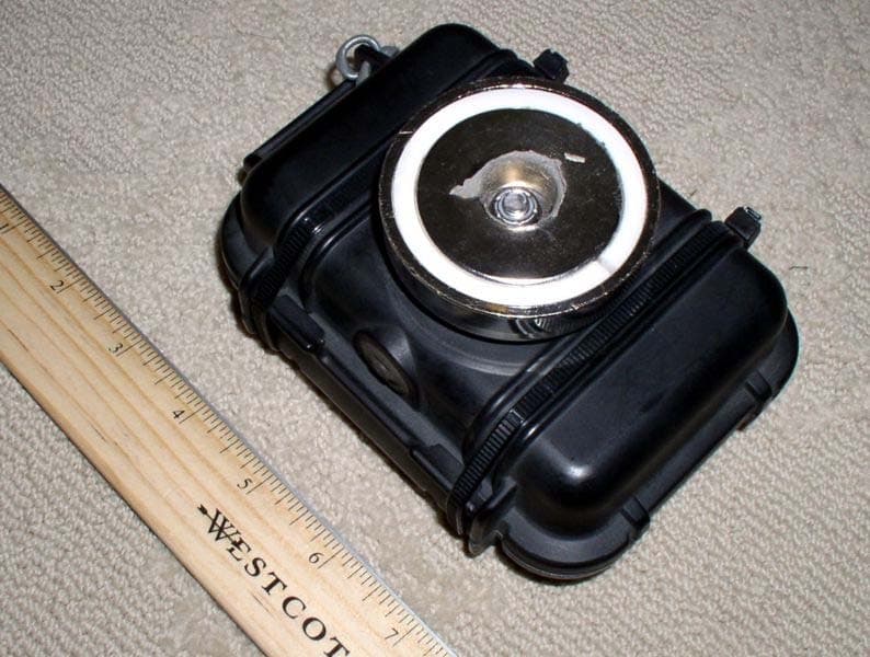
Q2USNT250
Feb 14, 2007Dual BandGSM W/ GPS Tracking & BeaconTechnology
Equipment Class
TNB - Licensed Non-Broadcast Station Transmitter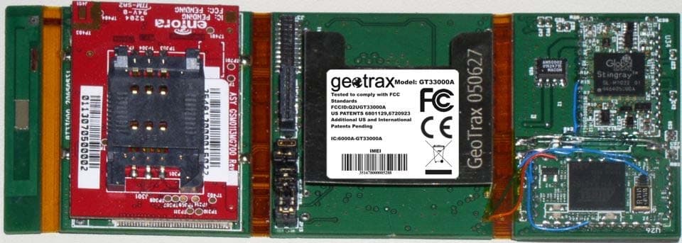
Q2UGT33000A
Aug 30, 2005GSM Multi-Band Self-Contained GPS/Beacon Device
Equipment Class
PCB - PCS Licensed Transmitter
Q2U-GT69000
May 13, 2003PCS/GSM 1900MHz Self-Contained GPS Device
Equipment Class
PCB - PCS Licensed Transmitter