Q2UGT33000AGSM Multi-Band Self-Contained GPS/Beacon Device
GeoTrax Protection LLC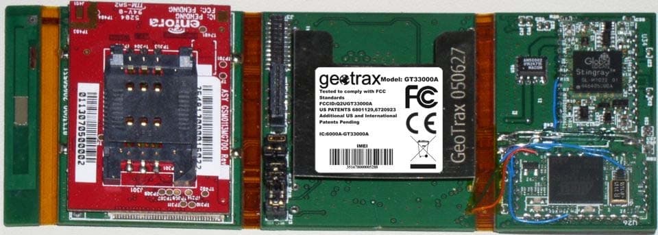
Click to zoom
Application Details
- Equipment Class
- PCB - PCS Licensed Transmitter
- Date of Grant
- Aug 30, 2005
- Application Purpose
- Original Equipment
- Date of Application
- Aug 30, 2005
- Equipment Note
- GSM Multi-Band Self-Contained GPS/Beacon Device
- Frequency Range
- 219.56000000 - 219.64000000
- Company
- GeoTrax Protection LLC
- Country
- United States
Documents & Files
Document Text
Text extracted from the exhibit documents filed with the FCC. Open a document above to read the original.
Users Manual
Global Pursuit Systems is one of the USCPC Group of Companies ESP CASH TRACKER USER GUIDE Rev. July 2003 Global Pursuit Systems is one of the USCPC Group of Companies PRODUCT DESCRIPTION The ESP is the most advanced product available for the covert tracking of stolen cash. It encompasses multiple technologies to provide the user with the most capable means of locating currency after it is stolen. The technologies included are (1) a Global Positioning Satellite (GPS) receiver, (2) a cellular telephone modem and (3) a radio frequency (RF) transmitter. Each of these technologies require the proper handling and care of the device. QUESTIONS & SERVICE Should you have any questions regarding the ESP or feel you need service, please contact us at the following: USCPC/Global Pursuit Systems 16611 E. Laser Drive Fountain Hills, AZ 85268 Tel: (480) 837-3773 Fax: (480) 837-3774 DEVICE HANDLING First and foremost, it is important to realize that this device is an electronic assembly. While it was designed and constructed to withstand the proper handling and use without damaging the unit, improper handling of the device may damage the device and render it useless. The device should be handled with care. Please do not drop the device or try to bend the device to see how flexible it is. However, you should feel very confident that you can handle the device as you would any electronic device. Normal transport of the device between cash drawers, if necessary, can be done without damaging the device. As the device contains transmitted radio frequency waves, caution should be used when handling the device near the body and in particular near the head. However, be advised that the device uses commercially available radio frequency assemblies that have been shielded and the device has received the certification from the FCC that under the intended use of the product, the device will not cause any personal harm. Global Pursuit Systems is one of the USCPC Group of Companies USING THE DEVICE The ESP looks and feels like a stack of 100 bank notes. It is designed to be placed in a cash drawer and remain in the drawer until needed and used in a robbery situation. One of the most critical components to the device functionality is the battery -- as it is needed to power the device. The device incorporates a magnetic reed switch to keep the device in an off/dormant position as long as the device remains on the provided magnetic base. Therefore, the device should always remain on the magnetic base unless being used in a robbery. Using the device when needed in a robbery is very simple. If you experience a robbery situation and you are going to give the criminal the money in your cash drawer then please remember the following: 1. Follow your normal robbery procedures! 2. To minimize the likelihood of the bank robber detecting the ESP the device should be, if possible, surrounded with the other bills from the drawer 3. Hand the entire stack of money and the ESP to the perpetrator or place it in a bag if provided. Avoid trying to pass the ESP to the perpetrator as a stand-alone item as the detection of the device is probably likely in this scenario. 4. The ESP requires no special intervention by the user! There are no special buttons to push, as the device will activate once it is removed from the magnetic plate. CAUTIONS & REMINDERS The success of the device is determined by the condition of the device when it is used. In particular, the battery must have sufficient power to run the device. Please handle the device with care and keep it in the cash drawer and on the magnetic plate at all times. There are no user serviceable components and no need for anyone other than a qualified technician to service the device. The ESP does not know if the person carrying it is a bank employee or a bank robber. If the device needs to be removed from the teller drawer for any reason other than during a robbery, such as changing the band around the bills, then it is crucial that it only be removed for a few seconds at a time. If the device is off of the magnetic plate for more than 10 seconds, it will notify law enforcement personnel that a bank robbery is in process. To minimize the incidence of false alarms, an additional magnetic plate will be supplied to the bank branches. If you need to remove the device from the drawer, immediately place it on the additional magnetic plate. When you are ready to place the device back into the drawer, be sure to place it back on the magnetic plate in the drawer within a few seconds.
Cover Letter(s)
GeoTrax Protection LLC * PO Box 6021, Scottsdale, AZ 85261 Tel 480.477-4950 * Fax 480.477-4950 * www.geotrax.com Date: July 19, 2005 Compliance Certification Services Certification Division 561F Monterey Road Morgan Hill, CA 95037 To whom it may concern: We, the undersigned, hereby authorize the Testing Division of Compliance Engineering Services, Inc., d.b.a. Compliance Certification Services and hereafter referred to as CCS, to act on our behalf in all manners relating to application for equipment authorization, including signing of all documents relating to these matters. Any and all acts carried out by CCS on our behalf shall have the same effect as acts of our own. We, the undersigned, hereby certify that we are not subject to a denial of federal benefits, that includes FCC benefits, pursuant to Section 5301 of the Anti-Drug Abuse Act of 1988, 21 U.S.C. 853(a). In authorizing CCS Testing Division as our agent, we still recognize that we are responsible to: a) comply with the relevant provisions of the certification program; b) make all necessary arrangements for the conduct of the evaluation, including provision for examining documentation and access to all areas, records (including internal audit reports) and personnel for the purposes of evaluation (e.g. testing, inspection, assessment, surveillance, reassessment) and resolution of complaints; c) make claims regarding certification only in respect of the scope for which certification has been granted; d) do not use our product certification in such a manner as to GeoTrax Protection LLC * PO Box 6021, Scottsdale, AZ 85261 Tel 480.477-4950 * Fax 480.477-4950 * www.geotrax.com bring the Certification Division into disrepute and not make any statement regarding our product certification which the Certification Division may consider misleading or unauthorized; e) upon suspension or cancellation of certification, discontinue use of all advertising matter that contains any reference thereto and return any certification documents as required by the Certification Division; f) use certification only to indicate the products are certified as being in conformity with specified standards; g) endeavor to ensure that no certificate or report nor any part thereof is used in a misleading manner; h) ensure that any reference to our product certification in communication media such as documents, brochures or advertising, complies with the requirements of the Certification Division; i) keep a record of all complaints made known to the us relating to the product’s compliance with requirements of the relevant standard and to make these records available to the Certification Division when requested; j) take appropriate action with respect to such complaints and any deficiencies found in products or services that affect compliance with the requirements for certification; k) document the actions taken. GeoTrax Protection LLC * PO Box 6021, Scottsdale, AZ 85261 Tel 480.477-4950 * Fax 480.477-4950 * www.geotrax.com This authorization is valid until further written notice from the applicant. Sincerely Yours, ___________________________________________ Richard A Fuller Senior Vice-President GeoTrax Protection LLC
Cover Letter(s)
GeoTrax Protection LLC * PO Box 6021, Scottsdale, AZ 85261 Tel 480.477-4950 * Fax 480.477-4951 * www.geotrax.com July 11, 2005 Federal Communications Commission Equipment Authorization branch 7435 Oakland Mills Road Columbia, MD 21046 Re: Request for Confidentiality Gentlemen: In reference to the application under FCC ID:Q2UGT33000A, and pursuant to Sections 0.457(d)(l)(ii) and 0.459 of the Commission’s Rules, the Applicant hereby requests confidential treatment of the accompanying information as outlined below: Schematics Block Diagrams Theory of Operation. These documents contain detailed system and equipment description and related information about the product that GeoTrax Protection LLC considers to be proprietary, confidential, and a custom design and, otherwise, would not release to the general public. Since this design is a basis from which future technological products will evolve, GeoTrax Protection LLC considers that this information would be of benefit to its competitors, and that disclosure of the information in these documents would give competitors an unfair advantage in the market. Sincerely, ___________________________________________ Richard A Fuller Senior Vice-President GeoTrax Protection LLC
External Photos
4.2 Internal and External Photos Due to the operational nature of the device, the external and internal of the device are the same. This is the actual device contained within the packaging/enclosure. Figure 4.2a shows the indicated region for FCC Labeling along with the internal photo of the top of the EUT. Figure 4.2b is a blow-up of the FCC product label and Figure 4.2c is the internal photo of the bottom of the EUT. Figure 4.2a. External/Internal Photo Top (with labeling) Figure 4.2b. Blow-up of the label GeoTrax Protection Confidential and Proprietary – Do Not Disclose Page 14 of 30 Figure 4.2c. External/Internal Photo Bottom GeoTrax Protection Confidential and Proprietary – Do Not Disclose Page 15 of 30
ID Label/Location Info
4.2 Internal and External Photos Due to the operational nature of the device, the external and internal of the device are the same. This is the actual device contained within the packaging/enclosure. Figure 4.2a shows the indicated region for FCC Labeling along with the internal photo of the top of the EUT. Figure 4.2b is a blow-up of the FCC product label and Figure 4.2c is the internal photo of the bottom of the EUT. Figure 4.2a. External/Internal Photo Top (with labeling) Figure 4.2b. Blow-up of the label GeoTrax Protection Confidential and Proprietary – Do Not Disclose Page 14 of 30 Figure 4.2c. External/Internal Photo Bottom GeoTrax Protection Confidential and Proprietary – Do Not Disclose Page 15 of 30
Parts List/Tune Up Info
5.0 Parts and Tuneup Procedure 5.1 GSM Module Tuneup Procedure Each modem is tested during routine supplier testing; • The modems are tested to GSM standards using an Agilent 8960 GSM test set. • Multiple channels and power levels are tested and if correction is necessary. • If correction is necessary, the "Automatic Power Control" software tables are adjusted in the modem's Flash memory. • After passing all tests, the modem is labeled and assigned an IMEI During final assembly of the GT33000A, the signal power is verified to be within 5 dB of nominal levels. 5.2 GPS Section Tuneup Procedure During final assembly if the GT33000A, the signal levels of actual GPS satellites are recorded. These are compared to past results and if they are within 5 dB. 5.3 RF Beacon Section Tuneup Procedure Each completed GT33000A is tested for RF Beacon operation. A beacon receiver (Wildlife Materials model TRX-3S) is used during final assembly to verify that the power level is normal for its sole operating power level. Normal is indicated by the peak number of LEDs lit during beacon operation. 5.4 Device Tuneup Procedure Results from sections 5.1, 5.2 and 5.3 are combined and if all levels are within normal operating parameters a label is printed and adhered to the device. An electronic record is made that the device has passed inspection and the signal levels of the tests. GeoTrax Protection Confidential and Proprietary – Do Not Disclose Page 16 of 30
Parts List/Tune Up Info
3.4 Summary of Design Characteristics Type of Emissions: RF Beacon Transmitter: Pulsed Carrier Wave, 2K98P0N GSM Tranceiver: As specified in ITU-T G.722, 200KD2E Frequency Range: RF Beacon Transmitter: US: 219.56 MHz 219.60(nominal) MHz 219.64 MHz Europe: 433.92 MHz GSM: Band 1 (US-PCS1900) Tx: 1850-1910 MHz Rx: 1930-1990 MHz Band 2 (US-GSM850) Tx:824.2 - 848.8 MHz Rx: 869.2 - 893.8 MH Band 3 (Europe – DCS1800) Tx: 1710.2 - 1784.8 MHz Rx: 1805.2 - 1879.8 MHz Band 4 (Europe – GSM900) Tx: 880.2 - 914.8 MHz Rx: 925.2 - 959.8 MHz Necessary Bandwidth: RF Beacon Transmitter: <6.25 kHz/channel GSM: 200 kHz/channel; (US) PCS1900: 298 channels (US) GSM850: 121 channels (Europe) GSM900: 171 channels (Europe) DCS1800: 371 channels Type of Modulation: RF Beacon Transmitter: None GSM: GMSK Operating Power Values: RF Beacon Transmitter: 20±2 dBm nominal maximum output power GSM: PCS1900 Class 1 (1 W): 30±2 dBm nominal maximum output power GSM850 Class 4 (2 W): 33±2 dBm nominal maximum output power DCS1800 Class 1 (1 W): 30±2 dBm nominal maximum output power GSM900 Class 4 (2 W): 33±2 dBm nominal maximum output power GeoTrax Protection Confidential and Proprietary – Do Not Disclose Page 11 of 30 DC Voltage applied: 3.3-4.4V supplied by battery DC Current: 2.0A Peak (burst), 400 mA average, and 10 mA sleep-mode ~0 μA idle-mode (on magnetic plate) Antennas: RF Beacon: Loop (0 dBi peak gain) GPS: Cavity type (0 dBi peak gain) GSM: Dual-folded monopole Pattern: omnidirectional Peak Gain: 0±3 dBi S11 (850MHz): -4.079 dB S11 (900 MHz): -5.036 dB S11 (1800 MHz): -4.839 dB S11 (1900 MHz): -5.097 dB Overall Dimensions: Thickness: 8.80mm (0.3465") Width: 47.50mm (1.870") - PCB width Length: 120.52mm (4.745") – up to 8.78mm (0.346”) may extend into monetary riffle GeoTrax Protection Confidential and Proprietary – Do Not Disclose Page 12 of 30
Test Report
FCC CFR47 PART 22H & 24E CERTIFICATION TEST REPORT FOR GSM MULTI-BAND SELF-CONTAINED GPS TRACKING DEVICE WITH BEACON TECHNOLOGY MODEL NUMBER: GT33000A FCC ID: Q2UGT33000A REPORT NUMBER: 05U3574-2 ISSUE DATE: AUGUST 14, 2005 Prepared for GEOTRAX PROTECTION LLC PO BOX 6021 SCTTSDALE, AZ 85261 Prepared by COMPLIANCE ENGINEERING SERVICES, INC. d.b.a. COMPLIANCE CERTIFICATION SERVICES 561F MONTEREY ROAD, MORGAN HILL, CA 95037, USA TEL: (408) 463-0885 FAX: (408) 463-0888 REPORT NO: 05U3574-2 DATE: AUGUST 14, 2005 EUT: GSM Multi-Band Self-contained GPS Tracking Device FCC ID: Q2UGT33000A Page 2 of 29 COMPLIANCE CERTIFICATION SERVICES DOCUMENT NO: CCSUP4031A 561F MONTEREY ROAD, MORGAN HILL, CA 95037 USA TEL: (408) 463-0885 FAX: (408) 463-0888 This report shall not be reproduced except in full, without the written approval of CCS. Revision History Rev. Issue Date Revisions Revised By A 8/14/05 Initial Issue Thu REPORT NO: 05U3574-2 DATE: AUGUST 14, 2005 EUT: GSM Multi-Band Self-contained GPS Tracking Device FCC ID: Q2UGT33000A Page 3 of 29 COMPLIANCE CERTIFICATION SERVICES DOCUMENT NO: CCSUP4031A 561F MONTEREY ROAD, MORGAN HILL, CA 95037 USA TEL: (408) 463-0885 FAX: (408) 463-0888 This report shall not be reproduced except in full, without the written approval of CCS. TABLE OF CONTENTS 1. ATTESTATION OF TEST RESULTS............................................................................................. 4 2. TEST METHODOLOGY .................................................................................................................. 5 3. CROSS REFERENCE TO OTHER REPORTS ON THIS PRODUCT ....................................... 5 4. FACILITIES AND ACCREDITATION .......................................................................................... 5 5. CALIBRATION AND UNCERTAINTY.......................................................................................... 5 5.1. MEASURING INSTRUMENT CALIBRATION ............................................................................. 5 5.2. MEASUREMENT UNCERTAINTY ............................................................................................... 5 6. EQUIPMENT UNDER TEST............................................................................................................6 6.1. DESCRIPTION OF EUT ..............................................................................................................6 6.2. MAXIMUM OUTPUT POWER .................................................................................................... 6 6.3. DESCRIPTION OF AVAILABLE ANTENNAS ............................................................................. 6 6.4. SOFTWARE AND FIRMWARE .................................................................................................... 6 6.5. WORST-CASE CONFIGURATION AND MODE......................................................................... 7 6.6. DESCRIPTION OF TEST SETUP ................................................................................................ 7 7. TEST AND MEASUREMENT EQUIPMENT ................................................................................ 9 8. LIMITS AND RESULTS ................................................................................................................. 10 8.1. 99 % BANDWIDTH .................................................................................................................... 10 8.2. RF POWER OUTPUT.................................................................................................................17 8.3. FIELD STRENGTH OF SPURIOUS RADIATION..................................................................... 20 9. SETUP PHOTOS .............................................................................................................................. 24 REPORT NO: 05U3574-2 DATE: AUGUST 14, 2005 EUT: GSM Multi-Band Self-contained GPS Tracking Device FCC ID: Q2UGT33000A Page 4 of 29 COMPLIANCE CERTIFICATION SERVICES DOCUMENT NO: CCSUP4031A 561F MONTEREY ROAD, MORGAN HILL, CA 95037 USA TEL: (408) 463-0885 FAX: (408) 463-0888 This report shall not be reproduced except in full, without the written approval of CCS. 1. ATTESTATION OF TEST RESULTS COMPANY NAME: GEOTRAX PROTECTION LLC P O BOX 6021 SCOTTSDALE AZ 85261, U.S.A EUT DESCRIPTION: GSM MULTI-BAND SELF-CONTAINED GPS TRACKIG DEVICE WITH BEACON TECHNOLOGY MODEL: GT33000A SERIAL NUMBER: GT33000_050531_0001 DATE TESTED: JULY20-23, 2005 APPLICABLE STANDARDS STANDARD TEST RESULTS FCC PART 22 H and 24 E NO NON-COMPLIANCE NOTED Compliance Certification Services, Inc. tested the above equipment in accordance with the requirements set forth in the above standards. The test results show that the equipment tested is capable of demonstrating compliance with the requirements as documented in this report. Note: The results documented in this report apply only to the tested sample, under the conditions and modes of operation as described herein. This document may not be altered or revised in any way unless done so by Compliance Certification Services and all revisions are duly noted in the revisions section. Any alteration of this document not carried out by Compliance Certification Services will constitute fraud and shall nullify the document. No part of this report may be used to claim product certification, approval, or endorsement by NVLAP, NIST, or any government agency. Approved & Released For CCS By: Tested By: THU CHAN CHIN PANG EMC SUPERVISOR EMC ENGINEER COMPLIANCE CERTIFICATION SERVICES COMPLIANCE CERTIFICATION SERVICES REPORT NO: 05U3574-2 DATE: AUGUST 14, 2005 EUT: GSM Multi-Band Self-contained GPS Tracking Device FCC ID: Q2UGT33000A Page 5 of 29 COMPLIANCE CERTIFICATION SERVICES DOCUMENT NO: CCSUP4031A 561F MONTEREY ROAD, MORGAN HILL, CA 95037 USA TEL: (408) 463-0885 FAX: (408) 463-0888 This report shall not be reproduced except in full, without the written approval of CCS. 2. TEST METHODOLOGY The tests documented in this report wer…
Text truncated - open the document above for the full version.
Test Report
Nemko Test Report: 3L0477RUS2Rev2 Applicant: Enfora Inc. 661 E/ 18 th Street Plano, Texas 75074 Equipment Under Test: Aspen – GSM/GPRS Wireless Modem (E.U.T.) GSM0108 In Accordance With: FCC Parts 24, Subpart E Broadband PCS Subscriber Station Tested By: Nemko Dallas Inc. 802 N. Kealy Lewisville, TX 75057-3136 Authorized By: Tom Tidwell, Frontline Manager Date: 29Sept03 Total Number of Pages: 38 Nemko Dallas FCC PARTS 2 and 24 GSM/GPRS Wireless Modem EQUIPMENT: GSM0108 Report No.: 3L0477RUS2 Page 2 of 38 Table of Contents Section 1. Summary of Test Results.....................................................................3 Section 2. General Equipment Specification........................................................5 Section 3. RF Power Output...................................................................................7 Section 4. Occupied Bandwidth............................................................................8 Section 5. Spurious Emissions at Antenna Terminals......................................10 Section 6. Field Strength of Spurious.................................................................24 Section 7. Frequency Stability.............................................................................27 Section 8. Test Equipment List............................................................................28 ANNEX A - TEST METHODOLOGIES.......................................................................29 ANNEX B - TEST DIAGRAMS....................................................................................35 Nemko Dallas FCC PARTS 2 and 24 GSM/GPRS Wireless Modem EQUIPMENT: GSM0108 Report No.: 3L0477RUS2 Page 3 of 38 Section 1. Summary of Test Results Manufacturer: Enfora Inc. Model No.: GSM0108 Serial No.: 28 General: All measurements are traceable to national standards. These tests were conducted on a sample of the equipment for the purpose of demonstrating compliance with FCC Part 24, Subpart E. New Submission Production Unit Class II Permissive Change Pre-Production Unit THIS TEST REPORT RELATES ONLY TO THE ITEM(S) TESTED. THE FOLLOWING DEVIATIONS FROM, ADDITIONS TO, OR EXCLUSIONS FROM THE TEST SPECIFICATIONS HAVE BEEN MADE. See “ Summary of Test Data”. TESTED BY: ____Eldon Berry ______ DATE: _26 Aug., 2003_ Nemko Dallas Inc. authorizes the above named company to reproduce this report provided it is reproduced in its entirety and for use by the company’s employees only. Any use which a third party makes of this report, or any reliance on or decisions to be made based on it, are the responsibility of such third parties. Nemko Dallas Inc. accepts no responsibility for damages, if any, suffered by any third party as a result of decisions made or actions based on this report. This report applies only to the items tested. Nemko Dallas FCC PARTS 2 and 24 GSM/GPRS Wireless Modem EQUIPMENT: GSM0108 Report No.: 3L0477RUS2 Page 4 of 38 Summary Of Test Data NAME OF TEST PARA. NO. SPEC. RESULT RF Power Output 24.232 2W eirp Complies Occupied Bandwidth (TDMA) 24.238 Not Specified Complies Spurious Emissions at Antenna Terminals 24.238(a) -13 dBm Complies Field Strength of Spurious Emissions 24.238(a) -13 dBm E.I.R.P. Complies Frequency Stability 24.235 +/- 0.05 ppm Complies Footnotes: Nemko Dallas FCC PARTS 2 and 24 GSM/GPRS Wireless Modem EQUIPMENT: GSM0108 Report No.: 3L0477RUS2 Page 5 of 38 Section 2. General Equipment Specification Supply Voltage Input: 3.3 - 5 Vdc Frequency Bands: Block A 1850 – 1865 MHz Block D 1865 – 1870 MHz Block B 1870 – 1885 MHz Block E 1885 – 1890 MHz Block F : 1890 – 1895 MHz Block C 1895 – 1910 MHz GPRS 270KG7W Type of Modulation and Designator: Output Impedance: 50 ohms RF Output (Rated): 1 Watt Nemko Dallas FCC PARTS 2 and 24 GSM/GPRS Wireless Modem EQUIPMENT: GSM0108 Report No.: 3L0477RUS2 Page 6 of 38 System Description This device is a wireless GSM/GPRS wireless modem that operates in the PCS band and in the 800 MHz “AMPS” band. System Diagram Nemko Dallas FCC PARTS 2 and 24 GSM/GPRS Wireless Modem EQUIPMENT: GSM0108 Report No.: 3L0477RUS2 Page 7 of 38 Section 3. RF Power Output NAME OF TEST: RF Power Output PARA. NO.: 24.232(b) TESTED BY: Eldon Berry DATE: 22Aug03 Test Results: Complies. Measurement Data: Typical antenna gain is 3.3 dBi. Thus the maximum eirp from above would be 29.8 dBm + 3.3 dBi = 33.1 dBm (2 watts). RF Power Output (Conducted) Job No.:3L0477RDate:8/22/03 Specification:CFR 47, Part 24Temperature(°C):21 Tested By:Eldon BerryHumidity(%)50 E.U.T.:GSM0108 Configuration:EUT on test fixture. Detector:Average Test Equipment Used: Power Meter:E4418BDirectional Coupler: Power Sensor:E9304ACable #1:1083 Load:Cable #2: Spectrum Analyzer:NACable #3: Attenuator #11604Cable #4: Attenuator #2:Cable #5: Attenuator #3:Cable #6: Attenuator #4:Power Splitter: Measurement Uncertainty:+/- .7 dB FrequencyModulationOutput PowerOutput MHzType(dBm)Power (mW) 1850.2512GPRS29.8954.99 1880.2662GPRS29.7933.25 1909.8810GPRS28.8758.58 Power meter set for 12.5 % duty cycle. Cable and attenuator verified with generator # 1053 Channel Nemko Dallas FCC PARTS 2 and 24 GSM/GPRS Wireless Modem EQUIPMENT: GSM0108 Report No.: 3L0477RUS2 Page 8 of 38 Section 4. Occupied Bandwidth NAME OF TEST: Occupied Bandwidth PARA. NO.: 24.238 TESTED BY: Eldon Berry DATE: 22Aug03 Test Results: Complies. Test Data: See attached plots. Nemko Dallas FCC PARTS 2 and 24 GSM/GPRS Wireless Modem EQUIPMENT: GSM0108 Report No.: 3L0477RUS2 Page 9 of 38 Test Plot – Occupied Bandwidth Nemko Dallas, Inc. Data Plot Page 1 of1 Complete X Job No.:3L0477R Date:8/22/03Preliminary: Specification:Temperature(°C):22 Tested By:Eldon BerryRelative Humidity(%)50 E.U.T.: Configuration: Sample Number:1 Location:Lab 1RBW:Refer to plotsMeasurement Detector Type:PeakVBW:Refer to plots Distance:N/Am Test Equipment Used Antenna: Directional Coupler: Pre-Amp: Cable #1:1083 Filter: Cable #2: Receiver:1036Cable #3: Attenuator #11604Cable #4: Attenuator #2: Mixer: Additional equipment u…
Text truncated - open the document above for the full version.
Test Report
. FCC CFR47 PART 90 REQUIREMENT CERTIFICATION TEST REPORT FOR GSM MULTI-BAND SELF-CONTAINED GPS TRACKING DEVICE WITH BEACON TECHNOLOGY MODEL NUMBER: GT33000A FCC ID: Q2UGT33000A REPORT NUMBER: 05U3574-1 ISSUE DATE: AUGUST 11, 2005 Prepared for GEOTRAX PROTECTION LLC. PO BOX 6021 SCOTTSDALE, AZ 85261 Prepared by COMPLIANCE ENGINEERING SERVICES, INC. d.b.a. COMPLIANCE CERTIFICATION SERVICES 561F MONTEREY ROAD, MORGAN HILL, CA 95037, USA TEL: (408) 463-0885 FAX: (408) 463-0888 REPORT NO: 05U3574-1 DATE: AUGUST 04, 2005 EUT: GSM Multi-Band Self-contained GPS Tracking Device FCC ID: Q2UGT33000A Page 2 of 23 COMPLIANCE CERTIFICATION SERVICES DOCUMENT NO: CCSUP4031A 561F MONTEREY ROAD, MORGAN HILL, CA 95037 USA TEL: (408) 463-0885 FAX: (408) 463-0888 This report shall not be reproduced except in full, without the written approval of CCS. Revision History Rev. Issue Date Revisions Revised By A 8/11/05 Initial Issue Thu REPORT NO: 05U3574-1 DATE: AUGUST 04, 2005 EUT: GSM Multi-Band Self-contained GPS Tracking Device FCC ID: Q2UGT33000A Page 3 of 23 COMPLIANCE CERTIFICATION SERVICES DOCUMENT NO: CCSUP4031A 561F MONTEREY ROAD, MORGAN HILL, CA 95037 USA TEL: (408) 463-0885 FAX: (408) 463-0888 This report shall not be reproduced except in full, without the written approval of CCS. TABLE OF CONTENTS 1. ATTESTATION OF TEST RESULTS.................................................................................. 4 2. TEST METHODOLOGY ...................................................................................................... 5 3. FACILITIES AND ACCREDITATION................................................................................ 5 4. CALIBRATION AND UNCERTAINTY .............................................................................. 5 4.1. MEASURING INSTRUMENT CALIBRATION ..................................................... 5 4.2. MEASUREMENT UNCERTAINTY ........................................................................ 5 5. EQUIPMENT UNDER TEST................................................................................................ 6 5.1. DESCRIPTION OF EUT ........................................................................................... 6 5.2. MAXIMUM OUTPUT POWER ............................................................................... 6 5.3. DESCRIPTION OF AVAILABLE ANTENNAS ..................................................... 6 5.4. DESCRIPTION OF TEST SETUP ............................................................................ 7 6. TEST AND MEASUREMENT EQUIPMENT ..................................................................... 8 7. LIMITS AND RESULTS....................................................................................................... 9 7.1. OUTPUT POWER MEASUREMENT ..................................................................... 9 7.2. EMISSION BANDWIDTH ..................................................................................... 11 7.3. FIELD STRENGTH OF SPURIOUS EMISSION .................................................. 13 7.4. FREQUENCY STABILITY MEASUREMENT..................................................... 17 8. SETUP PHOTOS ................................................................................................................. 19 REPORT NO: 05U3574-1 DATE: AUGUST 04, 2005 EUT: GSM Multi-Band Self-contained GPS Tracking Device FCC ID: Q2UGT33000A Page 4 of 23 COMPLIANCE CERTIFICATION SERVICES DOCUMENT NO: CCSUP4031A 561F MONTEREY ROAD, MORGAN HILL, CA 95037 USA TEL: (408) 463-0885 FAX: (408) 463-0888 This report shall not be reproduced except in full, without the written approval of CCS. 1. ATTESTATION OF TEST RESULTS COMPANY NAME: GEOTRAX PROTECTION LLC. PO BOX 6021 SCOTTSDALE, AZ 85261 EUT DESCRIPTION: GSM Multi-Band Self-contained GPS Tracking Device With Beacon Technology MODEL: GT33000A SERIAL NUMBER: GT33000_050531_0001 DATE TESTED: JULY 20-23, 2005 APPLICABLE STANDARDS STANDARD TEST RESULTS FCC PART 90 NO NON-COMPLIANCE NOTED Compliance Certification Services, Inc. tested the above equipment in accordance with the requirements set forth in the above standards. The test results show that the equipment tested is capable of demonstrating compliance with the requirements as documented in thi…
Text truncated - open the document above for the full version.
Contact Information
Applicant
Richard A Fuller(Sr VP of Technology and Business Development)
Test Firm
Compliance Certification Services IncSteve Cheng
Technical Specifications
| # | Rule Parts | Frequency Range | Power Output | Emission | Tolerance |
|---|---|---|---|---|---|
| 3 | 9 | 219.56 MHz - 219.64 MHz | 8.00 µW | 2K48P0N | 0.13 ppm |
Other Applications from GeoTrax Protection LLC
Q2USNT250
Feb 14, 2007Dual BandGSM W/ GPS Tracking & BeaconTechnology
Equipment Class
TNB - Licensed Non-Broadcast Station Transmitter
Q2U-GT69000F
Feb 11, 2004GSM 1900MHz GPS Device W/Beacon Technology
Equipment Class
TNB - Licensed Non-Broadcast Station Transmitter
Q2U-GT69000
May 13, 2003PCS/GSM 1900MHz Self-Contained GPS Device
Equipment Class
PCB - PCS Licensed Transmitter