Q37-TKW40815PCS1900 MHz vehicle tracking system
Thermo King Corporation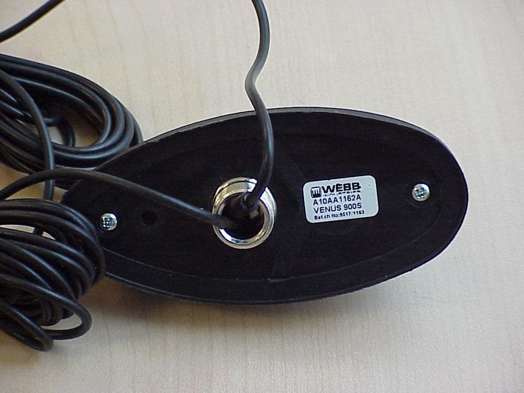
Click to zoom
Application Details
- Equipment Class
- PCB - PCS Licensed Transmitter
- Date of Grant
- Jun 09, 2003
- Application Purpose
- Original Equipment
- Date of Application
- Jun 09, 2003
- Equipment Note
- PCS1900 MHz vehicle tracking system
- Frequency Range
- 1850.20000000 - 1909.80000000
- Company
- Thermo King Corporation
- Country
- United States
Documents & Files
Document Text
Text extracted from the exhibit documents filed with the FCC. Open a document above to read the original.
Users Manual
THERMO KINGTHERMO KING KITKIT Subject:Trac-King GSM Units:SB units Benefits:This kit contains the parts needed to install the system 40-815 40-815 (1/03 JJ) Kit Contents: 192-2619Antenna Mounting Bracket1 292-2672Unit Mounting Brackets 2 3NSSTrac-King Unit.1 4NSSAntenna (GSM/GPS) with nut1 541-5168Trac-King harness 1 655-2977Screw - bracket2 755-1800Lockwasher2 855-2086Flatwasher2 955-7767Insert - threaded2 1055-9756Rivet - bracket2 1155-2201Flatwasher16 12203-498Wipe (Alcohol)1 1355-1844Screw8 1455-4223Nut8 Installation Instructions: 1.Attach antenna to the mounting bracket with the provided nut. 2.Mount the antenna assembly to the center of the condenser frame. Use the bracket as a template to mark and drill two 25/64 (10 mm)for the threaded inserts. Loosely attach the antenna assembly with the supplied screws, flatwashers and lockwashers. 3.Clean the plastic bulkhead with isopropyl alcohol wet wipes (203-498). Wipe dry. 4.Peal off the protective tape (double sided) and firmly press the bracket to the plastic bulkhead. Tighten hardware. Drill two 9/32 holes in the plastic bulkhead and install the rivets, seal the rivet heads with silicone calk to protect the integrity of the bulkhead. Do Not drill into bulkhead, use caulk to secure cables Maintain 3 inches of clearance between the and mufflercables Drill 25/64 (10 mm) Application Guidelines: For maximum bond strength the Ideal tape application is accomplished when temp. is between 70 to 100 F and the bond is allowed to dwell 72 hours. The bond strength is dependent upon the amount of adhesive-to-surface contact developed. Firm application pressure develops better adhesive contact and thus improves bond strength. 5.Route the antenna cables to the control box. Bandwrap cables to the lifting eye. Secure antenna cables to bulkhead with caulk. 6.Use bandwraps to secure the cables to the main harness and enter the control box through the harness grommet. Maintain 3 inches of clearance from the muffler, belts and pulleys. Attach GND wire to ground stud Attach 2S wire to no. 2 terminal Use brackets as a template to mount the moduleTrac-King Solder IGN wire to 8 wire on On-Off switch DAS Box Communications Harness (See instructions above) Clamp and Strain Relief (40-633) Connector (41-746) 3 Amp fuse Trac-King module Attach connectors finger tight 5.Attach the brackets to the Trac-King module, position the assembly above the TG-IV controller, mark and drill four (4) ¼ holes into the cover. The brackets must be used on units with or without DAS. 6Attach the antenna cables and the seven pin connector to Trac-King module, hand tight. 7.Attach the GND wire with terminal to the control box ground stud. 8.Solder the IGN wire to the #8 wire terminal of the On/Off switch. 9.Attach the 2S wire to the #2 terminal on the relay board. 10.Use an Amp terminal remover tool (204-737) to remove the two wires from the Communication harness 14 pin Amp connector (see below) and replace them with TxD and RxD wires. Thermoguard μPIV/μPV, Multitemp μPIV Trac-King Comm. PortPin No. TxDTxD21 RxDRxD22 Thermoguard μPVI (see Note 1)Thermoguard VI (see Note 2) Trac-King Comm. PortPin No.Trac-King Comm. PortPin No. TxDTxD311TxDTxD18 RxDRxD314RxDRxD14 oror TxDTxD23TxDTxD227 RxDRxD27RxDRxD219 Note 1.Comm. Port 2 is an option if Comm. Port 3 is not available. For Port 3, configure it to REMC OFF and TRMR OFF (for Port 2) in the super guarded access command. Note 2.If installation configuration has no remote display but with DAS installed, connect the TRAC-king to Comm. Port 1. Otherwise to Comm. Port 2. 11.Secure excess wires with bandwraps. 12.To test the unit refer to your user manual. Return the unit to service. To retrieve a user manual got to http://www.trac-king.com, enter your username and password. Click on the book with the question mark “?” on the cover (located to the far right of the TK Logo) and then click on download. Basic Troubleshooting Guide Symptom/ProblemAction 1. No web access. Call Technical support @ 952-887-2200/952-200-8389 or e-mail: [email protected] 2. Position, time, date and refrigeration data are not being displayed / web does not respond. Step 1: Check LED of the unit is flashing. Step 2: Check fuse and power connection. Step 2: Check GSM network coverage. Step 3: Call Technical support @952-887-2200/952-200-8389 or e-mail [email protected] 3. Position, time and date are not displayed- refrigeration data is available. Step 1: Check if antenna has line-of-sight to the Sky. Step 2: Check damage to GPS antenna its cable and hand tight connectors. Step 3: Call Technical support @ 952-887-2200/952-200-8389 or e-mail [email protected] 4. Refrigeration data not displayed, position time and date are available. Step 1: Review TX/RX connection –check trac-king loom cable. Step 2: Reset power of the Trac-King GSM Unit. Leave the power of the refrigeration unit on. Step 3: Check communication port. It should be set to datapac protocol or remote no/off. Refer to green book for changes of settings. Step 4: Verify from Table 1 if the software version of the micro is supported by this wireless product. Step 5: Call Technical support @ 952-887-2200/952-200-8389 or e-mail [email protected] Table 1 ControllerSupported Software RevisionUnsupported Software Revision TGVI 10901060 and below μP VI 4035 4032 4031 4030 Buzzer 4010 / 8888 μP V KOR 603 602 600 9607 611 610 601 μP IV Multi Zone (TCI) 2023 2022 2021 2015 2011 2001 μP IV + Single Temp 612310 510 512 3021 3022 9438 3020 420 412 Statement according FCC part 15.19 FCC identifier has to be on the equipment This device complies with Part 15 of the FCC Rules. Operation is subject to the following two conditions: (1) this device may not cause harmful interference, and (2) this device must accept any interference received, including interference that may cause undesired operation. Statement according FCC part 15.21 Modifications not expressly approved by Thermo King Corp. coul…
Text truncated - open the document above for the full version.
Users Manual
Web User Manual Doc. Issue 08/03/02 Rev. 3.1 - 1 - WEB USER MANUAL for the INTERNET BASED USER INTERFACE Web User Manual Doc. Issue 08/03/02 Rev. 3.1 - 2 - This document describes the use of the Trac-King Internet Interface as developed jointly by Thermo King Corporation of headquarters 314 West 90 th St, Minneapolis, USA and CELtrak Ltd. of headquarters Dunmore Rd. Tuam, Co. Galway, Ireland. This document provides a functional overview of the system and the features that are available in conjunction with Trac-King hardware. Further information on Trac- King and its related features is available from your Thermo King dealer and also from the website www.trac-king.com Web User Manual Doc. Issue 08/03/02 Rev. 3.1 - 3 - TABLE OF CONTENTS 1. INTRODUCTION......................................................................................................................................................4 1.1 Logging In...........................................................................................................................................................4 1.2 Homepage............................................................................................................................................................5 2. PHONEBOOK...........................................................................................................................................................6 2.1 Vehicle Address Books......................................................................................................................................6 2.2 Contacts...............................................................................................................................................................7 3. TOOLS.....................................................................................................................................................................9 3.1 Poll........................................................................................................................................................................9 3.2 Call-Back..........................................................................................................................................................10 3.3 Reset..................................................................................................................................................................11 3.4 Temperature.....................................................................................................................................................12 4. COMMANDS.........................................................................................................................................................13 4.1 Odometer..........................................................................................................................................................13 5. SETTINGS.............................................................................................................................................................14 5.1 Tracking List....................................................................................................................................................14 5.2 Sorting...............................................................................................................................................................15 5.3 Speed Limits.....................................................................................................................................................15 5.4 Temperature.....................................................................................................................................................16 6. MESSAGE.............................................................................................................................................................17 6.1 Send Message...................................................................................................................................................17 6.2 Read Message..................................................................................................................................................18 6.3 Auto-Answer.....................................................................................................................................................18 7. REPORTS..............................................................................................................................................................20 7.1 Report................................................................................................................................................................20 7.2 Reefer Utilisation............................................................................................................................................21 7.3 Trailer Utilisation...........................................................................................................................................22 7.4 Frequent Alarms..............................................................................................................................................22 7.5 Alarm History..................................................................................................................................................24 7.7 Temperature.....................................................................................................................................................24 8. DEALER / HELP..................................................................................................................................................26 8.1 Online Help......................................................................................................................................................26 8.2 Download Help File...…
Text truncated - open the document above for the full version.
External Photos
EUT – Top view EUT – Bottom view
ID Label/Location Info
Label location TYPE: TRAC-KING GSM This device complies with part 15 of the FCC Rules. MODEL: 907264. Operation is subjected to the following two conditions: S/N: 10701342. 1- this device may not cause harmful interference, and P/N: 40-815. 2 - this device must accept any interference received, IMEI: 50D228580003530 including interference that that may cause undesired operation. FCC ID USA: Q37-TKW40815 ID Canada: xxxxxxx Trac-King TM Global System for Mobile Communication © 2001 Thermo King Corporation
Internal Photos
PCB – Bottom view PCB – Top view shielded PCB – Top view unshielded PCB – Top view unshielded (close up)
RF Exposure Info
MPE Calculation for: Model: 90624 FCC ID: Q37-TKW40815 Calculations can be made to predict RF field strength and power density levels around typical RF sources using the general equations (3) and (4) on page 19 of the following FCC document: “OET Bulletin 65, Edition 97-01 - Evaluating Compliance with FCC Guidelines for Human Exposure to Radio frequency Electromagnetic Fields”. These equations are generally accurate in the far field of an antenna but will over predict power density in the near field, where they could be used for making a “worst case” prediction. S = PG/4πR 2 (3) Where S = power density (in appropriate units, e.g. mW/cm 2 ) P = power input to the antenna (in appropriate units e.g. mW) G = power gain of the antenna in the direction of interest relative to the isotropic radiator R = distance to the center of radiation of the antenna (appropriate units e.g. cm) or, S = EIRP/4πR 2 (4) Where EIRP = Equivalent Isotropically radiated power Calculation: EIRP: 22.33dBm (171mW) Calculated at distance of 20cm Power density = 171 / (4 x pi x 20 2 ) = 0.034 mW/cm 2 = 0.34 W/m 2 Limit: 1mW/cm 2 is the reference level for general public exposure according to the OET Bulletin 65, Edition 97-01 Table 1.
Test Report
TTI-P-G 081/94-A0 Accredited according to ISO/IEC 17025 Bluetooth Qualification Test Facility (BQTF) FCC listed # 101450 IC recognized # 3925 CETECOM Inc. 411 Dixon Landing Road Milpitas, CA 95035 U.S.A. Phone: + 1 (408) 586 6200 Fax: + 1 (408) 586 6299 E-mail: [email protected] http://www.cetecom.com CETECOM Inc. is a Delaware Corporation with Corporation number: 2113686 Board of Directors: Dr. Harald Ansorge, Dr. Klaus Matkey, Hans Peter May V1.1 2003-03-01 The BLUETOOTH trademarks are owned by Bluetooth SIG, Inc., U.S.A. and licensed to CETECOM Inc. © Copyright by CETECOM FCC Test Report Test report no.: EMC_459FCC24-2003_907264 FCC Part 24 / RSS 133 Model: (907264) FCC ID: Q37-TKW40815 Test report no.: EMC_459FCC24-2003_907264 Issue date: 2003-05-28 Page 2 (60) Table of Contents 1 General information 1.1 Notes 1.2 Testing laboratory 1.3 Details of applicant 1.4 Application details 1.5 Test item 1.6 Test standards 2 Technical test 2.1 Summary of test results 2.2 Test report 1 General information 1.1 Notes The test results of this test report relate exclusively to the test item specified in 1.5. The CETECOM Inc. does not assume responsibility for any conclusions and generalisations drawn from the test results with regard to other specimens or samples of the type of the equipment represented by the test item. The test report may only be reproduced or published in full. Reproduction or publication of extracts from the report requires the prior written approval of the CETECOM Inc. TEST REPORT PREPARED BY: EMC Engineer: Philip Kim 1.2 Testing laboratory CETECOM Inc. 411 Dixon Landing Road, Milpitas, CA-95035, USA Phone: +1 408 586 6200 Fax: +1 408 586 6299 E-mail: [email protected] Internet: www.cetecom.com Test report no.: EMC_459FCC24-2003_907264 Issue date: 2003-05-28 Page 3 (60) 1.3 Details of applicant Name : Thermo King Corp. Street : 314 West 90 th Street City / Zip Code : Minneapolis, MN 55420-3693 Country : USA Contact : Eduardo Tan Telephone : 952-887-2289 Tele-fax : 952-887-2371 e-mail : [email protected] 1.4 Application details Date of receipt of application : 2003-4-10 Date of receipt test item : 2003-4-10 Date of test : 2003-4-10/11 1.5 Test item Manufacturer : CELTRAK Ltd. Street : Dunmore Rd. City / Zip Code : Tuam Co. Galway Country : Ireland Model No. : 907264 Description : GSM/GPS vehicle tracking and temperature monitoring system. FCC-ID : Q37-TKW40815 Additional information Frequency : 1850.2MHz – 1909.8MHz for PCS 1900 Type of modulation : GMSK Number of channels : 299 for PCS 1900 Antenna : External (Model: Venus 900s for GSM900/1900+GPS incl. long cable) Power supply : 12Vdc Output power : 30.0dBm (1W) conducted peak power 22.33dBm (171mW) EIRP Extreme vol. Limits : Lower Limit: 9Vdc Nominal Voltage: 12.Vdc Upper Limit: 30Vdc Extreme temp. Tolerance : Lower Limit: -30 o C Upper Limit: 70 o C 1.6 Test standards FCC Part 24 / RSS133 r1 Test report no.: EMC_459FCC24-2003_907264 Issue date: 2003-05-28 Page 4 (60) 2 Technical test 2.1 Summary of test results No deviations from the technical specification(s) were ascertained in the course of the tests Performed Final Verdict: (only “passed” if all single measurements are “passed”) Passed Note: The tested unit 907264 will be used in vehicular environment and no AC source is required to use the EUT. Therefore, AC mains conducted emission under §15.207 will not be tested. Technical responsibility for area of testing: 2003-05-28 EMC & Radio Lothar Schmidt (Manager) Date Section Name Signature Responsible for test report and project leader: 2003-05-28 EMC & Radio Philip Kim (EMC Engineer) Date Section Name Signature Test report no.: EMC_459FCC24-2003_907264 Issue date: 2003-05-28 Page 5 (60) 2.2 Test report TEST REPORT Test report no.: EMC_459FCC24-2003_907264 (Model: 907264) Test report no.: EMC_459FCC24-2003_907264 Issue date: 2003-05-28 Page 6 (60) TEST REPORT REFERENCE PARAMETER TO BE MEASURED PARAGRAPH PAGE POWER OUTPUT SUBCLAUSE § 24.232 ............................................................................................. 7 EIRP Measurements .........................................................................................................................................................8 FREQUENCY STABILITY SUBCLAUSE § 24.235 ..............................................................................................12 OCCUPIED BANDWIDTH §2.1049 / §24.238 ....................................................................................... 14 EMISSIONS LIMITS §24.238 ............................................................................................................... 21 RADIATED SPURIOUS EMISSIONS .........................................................................................................................23 RECEIVER RADIATED EMISSIONS SUBCLAUSE § 15.209/RSS 133 .............................................................49 CONDUCTED SPURIOUS EMISSIONS .....................................................................................................................54 TEST EQUIPMENT AND ANCILLARIES USED FOR TESTS ............................................................... 58 BLOCK DIAGRAMS ...................................................................................................................................... 59 Conducted Testing..........................................................................................................................................................59 Radiated Testing.............................................................................................................................................................60 Test report no.: EMC_459FCC24-2003_907264 Issue date: 2003-05-28 Page 7 (60) POWER OUTPUT SUBCLAUSE § 24.232 Summary: During the process of testing, the EUT was controlled via Rhode & Schwarz Digital Radio Communication tester (CMD-55) to ensure max. Power transmission and proper modul…
Text truncated - open the document above for the full version.
Test Setup Photos
Test setup – Conducted Measurements Test setup – Radiated Measurements
Contact Information
Applicant
Uday Shankar(Telematics Leader)
Test Firm
Cetecom Inc.Lothar Schmidt
Technical Specifications
| # | Rule Parts | Frequency Range | Power Output | Emission | Tolerance |
|---|---|---|---|---|---|
| 1 | 24E | 1.85 GHz - 1.91 GHz | 171.00 mW | 300KGXW | 0.0300000000 ppm |
Other Applications from Thermo King Corporation

Q37TKV5LA
Oct 29, 2023TracKing V5
Equipment Class
DTS - Digital Transmission System
Q371E60326-3G
Apr 09, 2015Radio expansion board with GSM800 and 1900 and 802.11 b/g/n
Equipment Class
PCB - PCS Licensed Transmitter
Q371E60326REB
Apr 29, 2012Radio Expansion Board - Telematics for Transport Refrigeration
Equipment Class
PCB - PCS Licensed Transmitter