Q371E60326REBRadio Expansion Board - Telematics for Transport Refrigeration
Thermo King Corporation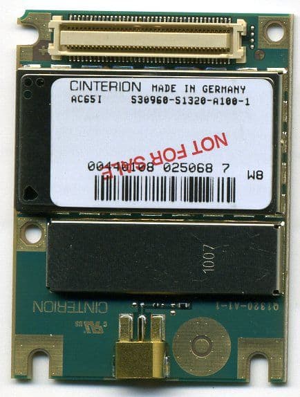
Click to zoom
Application Details
- Equipment Class
- PCB - PCS Licensed Transmitter
- Date of Grant
- Apr 29, 2012
- Application Purpose
- Original Equipment
- Date of Application
- Apr 29, 2012
- Equipment Note
- Radio Expansion Board - Telematics for Transport Refrigeration
- Frequency Range
- 1850.20000000 - 1909.80000000
- Company
- Thermo King Corporation
- Country
- United States
Documents & Files
Document Text
Text extracted from the exhibit documents filed with the FCC. Open a document above to read the original.
Users Manual
Page 1 of 15 Thermo King Corporation Proprietary Information REB Installation Guide Revision No.3 Approval Signature Date PROPRIETARY NOTICE This document contains information proprietary to Thermo King Corporation. It is submitted in confidence and is to be used solely for the purpose for which it is furnished and returned upon request. This document and such information is not to be reproduced, transmitted, disclosed or used otherwise in whole or in part without the written authorization of Thermo King Corporation. Revision History: Revision Level Description Date 1 S. Ed. Tan Draft Dec. 14, 2011 2 S. Ed. Tan March 13, 2010 3 S. Ed. Tan Added FCC and IC note as per Cetecom April, 5, 2012 Page 2 of 15 Thermo King Corporation Proprietary Information Page 3 of 15 Thermo King Corporation Proprietary Information Regulatory Statements: FCC: This device complies with Part 15 of the FCC Rules. Operation is subject to the following two conditions: (1) this device may not cause harmful interference, and (2) this device must accept any interference received, including interference that may cause undesired operation. Changes or modifications made to this equipment not expressly approved by Thermo King Corporation may void the FCC authorization to operate this equipment. NOTE: This equipment has been tested and found to comply with the limits for a Class B digital device, pursuant to Part 15 of the FCC Rules. These limits are designed to provide reasonable protection against harmful interference in a residential installation. This equipment generates, uses and can radiate radio frequency energy and, if not installed and used in accordance with the instructions, may cause harmful interference to radio communications. However, there is no guarantee that interference will not occur in a particular installation. If this equipment does cause harmful interference to radio or television reception, which can be determined by turning the equipment off and on, the user is encouraged to try to correct the interference by one or more of the following measures: Reorient or relocate the receiving antenna. Increase the separation between the equipment and receiver. Connect the equipment into an outlet on a circuit different from that to which the receiver is connected. Consult the dealer or an experienced radio/TV technician for help. Radiofrequency radiation exposure Information: This equipment complies with FCC radiation exposure limits set forth for an uncontrolled environment. This equipment should be installed and operated with minimum distance of 20 cm between the radiator and your body. This transmitter must not be co-located or operating in conjunction with any other antenna or transmitter. Page 4 of 15 Thermo King Corporation Proprietary Information IC: This device complies with Industry Canada licence-exempt RSS standard(s). Operation is subject to the following two conditions: (1) this device may not cause interference, and (2) this device must accept any interference, including interference that may cause undesired operation of the device. Le présent appareil est conforme aux CNR d'Industrie Canada applicables aux appareils radio exempts de licence. L'exploitation est autorisée aux deux conditions suivantes : (1) l'appareil ne doit pas produire de brouillage, et (2) l'utilisateur de l'appareil doit accepter tout brouillage radioélectrique subi, même si le brouillage est susceptible d'en compromettre le onctionnement. „Under Industry Canada regulations, this radio transmitter may only operate using an antenna of a type and maximum (or lesser) gain approved for the transmitter by Industry Canada. To reduce potential radio interference to other users, the antenna type and its gain should be so chosen that the equivalent isotropically radiated power (e.i.r.p.) is not more than that necessary for successful communication.‟ „Conformément à la réglementation d'Industrie Canada, le présent émetteur radio peut fonctionner avec une antenne d'un type et d'un gain maximal (ou inférieur) approuvé pour l'émetteur par Industrie Canada. Dans le but de réduire les risques de brouillage radioélectrique à l'intention des autres utilisateurs, il faut choisir le type d'antenne et son gain de sorte que la puissance isotrope rayonnée équivalente (p.i.r.e.) ne dépasse pas l'intensité nécessaire à l'établissement d'une communication satisfaisante.‟ Page 5 of 15 Thermo King Corporation Proprietary Information 1. Introduction: This document will describe how REB and the antenna system are installed in the Thermo King SB unit in the factory and in the field. 2. Installation of REB to the mother board SR3 controller. a. Plug- in REB with plastic housing to the SR3 controller board via connector RJ98. b. Secure board to the SR3 controller board using two screws provided in the kit. c. Mount the boards to the metal control box. See drawing for details. d. Connect antenna connectors to corresponding REB connectors. Please review connection and make sure the label match antenna and REB. e. Route Antenna cable as shown in the drawing below. f. Plug-in back-up battery. Page 6 of 15 Thermo King Corporation Proprietary Information Page 7 of 15 Thermo King Corporation Proprietary Information 3. REB Wi-Fi Configuration: 3.1 Required Materials: REB – Radio Expansion Board TDAC- Tracking Diagnostic and Configuration Tool- PC based application to configure REB REB adapter cable PN;41-9171 Wintrac cable : 204-918 + 44-9417 REB reset cable 3.2 Instructions: a) Connect Wintrac cable to the REB adapter cable as shown in figure 1. b) Connect reset cable as shown in figure 1. c) Unplug back-up battery Reset Cable Wintrac cable connected to REB Back-up battery plug REB Page 8 of 15 Thermo King Corporation Proprietary Information Figure 1. d. Launch TDAC application in your PC. See Figure 2. Figure 2 e. Turn TK unit ON (Controller and HMI running). f. Push and release reset button and immediately click START button in the TDAC appli…
Text truncated - open the document above for the full version.
Users Manual
© Copyright Celtrak Ltd 2011 TRACKING WEB USER MANUAL TK60178-8-OP-EN REV.3.3 TK60178-8-OP-EN Rev.3.3 Page 2 Contents SYSTEM OVERVIEW......................................................................................................................................... 4 CUSTOMER FLEET ..................................................................................................................................... 5 GSM/GPRS NETWORK ............................................................................................................................. 6 THERMO KING SERVER ............................................................................................................................. 7 CUSTOMER TERMINALS ............................................................................................................................. 8 LOGIN PAGE ....................................................................................................................................................... 9 USER LEVELS .......................................................................................................................................... 10 ERROR MESSAGES ................................................................................................................................... 11 GPRS CONNECTIVITY FUNCTIONS MATRIX .......................................................................................... 12 MAIN PAGE ....................................................................................................................................................... 13 VEHICLE SELECTION TREE ...................................................................................................................... 14 1 CLICK REPORTS ................................................................................................................................... 16 MENU BAR .............................................................................................................................................. 18 TRACK VEHICLES .......................................................................................................................................... 19 TRACKING LIST ....................................................................................................................................... 20 MESSAGES WINDOW ............................................................................................................................... 22 MAPS ................................................................................................................................................................... 23 MAP TOOLBAR ........................................................................................................................................ 25 FULL SCREEN MODE ............................................................................................................................... 27 SATELLITE/HYBRID MAPS ....................................................................................................................... 28 PAN/ZOOM .............................................................................................................................................. 30 VEHICLES ................................................................................................................................................ 31 POINTS OF INTEREST ................................................................................................................................ 32 LABELS .................................................................................................................................................... 33 GEO FENCES ............................................................................................................................................ 34 DATA MANAGEMENT .................................................................................................................................... 37 STANDARD REPORT CATEGORIES ........................................................................................................... 39 24 HOUR REEFER HISTORY REPORT ........................................................................................................ 40 ALARM HISTORY REPORT ....................................................................................................................... 41 CONTROLLER HISTORY REPORT .............................................................................................................. 42 CURRENT FLEET REPORT ........................................................................................................................ 43 GEO FENCE ACTIVITY BY GEO FENCE REPORT ........................................................................................ 44 DATA LOGGER TEMPERATURE HISTORY ................................................................................................. 45 GEO FENCE REPORT ................................................................................................................................ 46 OPERATIONS HISTORY REPORT ............................................................................................................... 47 POSITION HISTORY REPORT..................................................................................................................... 48 REEFER UTILISATION REPORT ................................................................................................................. 50 TKDL TEMPERATURE GRAPH ................................................................................................................. 51 TEMPERATURE CHART ............................................................................................................................ 52 TWO WAY AUDIT HISTORY REPORT ...........................................................…
Text truncated - open the document above for the full version.
Users Manual
TK60178-8-OP-EN Rev.3.3 Page 61 Stationary Vehicle Report (Not available in Certain Markets including USA) Note the user can define the stop duration. This is described as an occurrence of a stop of more than the specified duration. TK60178-8-OP-EN Rev.3.3 Page 62 Vehicle Summary Report (Not available in Certain Markets including USA) The Vehicle summary report can be run for up to a month. This report provides a summary of the vehicle Journeys by Day. This report also shows the average fuel consumption for the Vehicle. Working Duration = Time from first Ign On to last Ign. Off in a day. Note that if the vehicle is on and remains on past midnight then that journey is included in the first day Ign. On duration =The length of time the Ign is on in the day. Idling Duration = Length of time the Vehicle is moving at less than 15M per min (2kM/h) for at least 3Mins. Driving Duration = Ign On duration – Idling Duration. TK60178-8-OP-EN Rev.3.3 Page 63 Vehicle Utilisation Report (Not available in Certain Markets including USA) The Vehicle Utilisation Report is a summary of the Vehicle Utilisation over a period of time. Clicking on the Pie chart icon on the report shows the data in Pie Chart format. TK60178-8-OP-EN Rev.3.3 Page 64 Key Performance Indicators Explained (Not available in Certain Markets including USA) Introduction Key Performance Indicators are used to give a quick indication of Highest Hours Driven and Fuel Efficiency. Initially the user can select the period of the charts and the number of Vehicles to be shown on the charts. TK60178-8-OP-EN Rev.3.3 Page 65 Highest Hours Driven KPI The Highest Hours Driven KPI is fully automated and will display available data for the vehicles selected in the Vehicle Tree. Users can interact with the chart in a number of ways: • Graphs can be turned on and off by clicking on the coloured legend boxes • Similarly, data value labels can be turned on and off by clicking either on the individual graph bars or on the legend text • When a large amount of data is displayed, users can click and drag their mouse to zoom in on an area of interest and use the horizontal scrollbar at the top to view the next data series • How do you zoom out on the KPI chart? A “View All” icon appears in the top right hand corner of the graph. All right clicking provides a context menu with zoom function. TK60178-8-OP-EN Rev.3.3 Page 66 Fuel Efficiency KPI • Data for the fuel efficiency KPI is read from the CAN bus. TK60178-8-OP-EN Rev.3.3 Page 67 Administration The administration page allows the user to manage their TracKing system. It provides links to configuration pages to add users and vehicles. Note that the degree of access a user has to administration features is determined by their user level. The administration features are divided into four logical groups: Temperature; Vehicle administration; User administration and Miscellaneous. Temperature This section of the Administration page allows the user to configure the main temperature features related to the reefer and data logger. • Alarm Notifications • Two-Way Commands • Temperature Range Settings • Data Logger Downloads • Controller Logger Download (available in certain markets only) • Door Alarm Settings TK60178-8-OP-EN Rev.3.3 Page 68 Vehicle Administration In this section, the user can manage the details of vehicles in their fleet and arrange them into groups for effect tracking and reporting. Click on a topic below for further information. • Add Vehicle Group • Vehicle Group Search • Vehicle Search User Administration In this section, the user can manage the people involved in the TracKing system. Click on a topic for more information. • Add User • User Search Miscellaneous Many TracKing features provide configuration options to allow the customer to set up the system as best suits them. The administration of these features is handled in this section. Click on a topic for more information. • Contacts • POI Maintenance • Geo Fence Administration • Customizable reports • Scheduled Reports TK60178-8-OP-EN Rev.3.3 Page 69 Alarm Notifications TracKing can be configured to notify contacts when certain alarms occur. Any notifications which have been configured are listed on this Alarm Notifications page, accessed from the Temperature section. Add Click the Add icon to add a new alarm notification. This will open the Add/Edit Alarm page. Edit To edit an alarm: 1. Select the alarm by clicking the radio button next to it. 2. Click the Edit icon to open the Add/Edit Alarm page. Delete To delete an alarm: 1. Select the alarm by clicking the radio button next to it. 2. Click the Delete icon. Add/Edit Alarm The Alarm Details section of this page allows the user to define the settings for an alarm. The options are explained in more detail below. Note: The screenshot below shows a subset of the alarm options available. TK60178-8-OP-EN Rev.3.3 Page 70 Alarm Notification Name This is the name by which the alarm will be identified in the Alarm Notification list and elsewhere in the system. Select All This enables all the alarms. Alarm Conditions The alarm conditions consist of a code (e.g. 96) and a description (e.g. Low Fuel Level). The full list of alarm types will be displayed when the user opens the alarms notifications page. Check the box next to the alarm condition which is to be included in this particular list. TK60178-8-OP-EN Rev.3.3 Page 71 Notification Type Notification can be via SMS or email, or a combination of both. Recipients Enter the people who should be notified in the event of this alarm. Recipient must be added as a contact in order to appear in this list. Confirm Click 'Confirm' to save any changes. How Alarm Notifications Work When an alarm occurs that has a notification associated with it (defined in alarm notification list, Temperature alarms and Door alarms), the notification will be sent once to the recipients and will not be resent until either the alarm is cleared on the Reefer and re occurs or the ala…
Text truncated - open the document above for the full version.
External Photos
V2.0 2009-10-30 The BLUETOOTH trademarks are owned by Bluetooth SIG, Inc., U.S.A. and licensed to CETECOM Inc. © Copyright by CETECOM External EUT Pictures TEST REPORT #: EMC_TRANE_002_12001_EXT_PIC V2.0 2009-10-30 The BLUETOOTH trademarks are owned by Bluetooth SIG, Inc., U.S.A. and licensed to CETECOM Inc. © Copyright by CETECOM EUT pictures Project #: EMC_TRANE_002_12001_EXT_PIC FCC ID: Q37-1E60326REB Date: 2012-02-01 Page 3 of 5 Project #: EMC_TRANE_002_12001_EXT_PIC FCC ID: Q37-1E60326REB Date: 2012-02-01 Page 4 of 5 Antenna pictures Project #: EMC_TRANE_002_12001_EXT_PIC FCC ID: Q37-1E60326REB Date: 2012-02-01 Page 5 of 5
ID Label/Location Info
REB Label NOTES: The Radio Exposure Statement will not be part of the label but will be included in the Installation Guide due to the following reasons: 1. Small size board and plastic enclosure. 2. The board is mounted on top of a mother board are enclosed in a metal box, see illustration below. 3. The metal box is covered with plastic body therefore the radio board will not be seen by the user.
Internal Photos
V2.0 2009-10-30 The BLUETOOTH trademarks are owned by Bluetooth SIG, Inc., U.S.A. and licensed to CETECOM Inc. © Copyright by CETECOM Internal EUT Pictures TEST REPORT #: EMC_TRANE_002_12001_INT_PIC Project #: EMC_TRANE_002_12001_INT_PIC FCC ID: Q37-1E60326REB Date: 2012-02-01 Page 2 of 3 EUT pictures Project #: EMC_TRANE_002_12001_INT_PIC FCC ID: Q37-1E60326REB Date: 2012-02-01 Page 3 of 3
Operational Description
Low Profi le GPS Multi-band Antenna The Z3400 GPS Multi-Band antenna features an attractive modern design in a rugged low profi le housing. This antenna offers GPS plus quad-band coverage of global cellular frequency bands and a separate WiFi chan- nel. Features • Double RF coaxial feeds: GSM/CDMA/UMTS (1) and 2.4 GHz Wi-Fi (1) • GPS coaxial feed (1) • Stylish low profi le housing provides “omnidirectional” performance and adequate overhead clearance for trouble-free installation • Metal 3/4-inch stud mount with slotted jam nut provides single cable exit for easier installation and/or antenna replacement • Protective cable braid for added tolerance to extreme temperatures • IP67 compliant design with custom over molded gasket provides added protection against water or dust ingress under severe environ- mental conditions* Electrical Specifi cations GPS Antenna Frequency Band: 1575.42 +/- 1MHz (GPS L1) Amplifi er Gain without Antenna Element: 26 dB +/- 3 Nominal Impedance: 50 ohms Noise Figure (25°): 1.8 typical VSWR: 1.5:1 typical DC Current @ 5 Volts: 20 mA Nominal < 30 mA @ -40°C to +85° C (Filter Out-Of-Band) DC Voltage: 3-5 V (regulated) Grounding Protection: DC grounded Filtering: Hybrid (including pre-selector) Out-Of-Band Signal Rejection: 40 dB @ +/- 50 MHz typical PCTEL, Inc. www.antenna.com MOBILE ANTENNAS GPS & Multi-band Transit Antenna Mechanical Specifi cations HousingDimensionsCoax (3)Connectors UV resistant, Black Plastic 5.1” x 4.95” x 1.7” (129.6 x 125.8 x 43.1 mm) 15 feet PFP195 (RF feed) 15 feet PFP195 (WiFi feed) 15 feet RG-174/U (GPS feed) RP SMA Plug (Male) RP SMA Plug (Male) SMA Plug (Male) Environmental Specifi cations Operating / Storage TemperatureWeightIngress ProtectionHumidity -40°C to +85°C1.96 lbsIP67*95% Electrical Specifi cations - RF Antennas Model Z3400 Operating Frequencies Polarization Nominal Impedance Typical Gain (dBi) No Cable / With Cable Max. VSWR Max. Power GSM/CDMA/ UMTS 806-960 MHz 1710-2170 MHz Vertical, linear 50 ohms 3 / 1.3 4 / 1.4 < 2.2:1 < 2.0:1 20 Watts 2.4 GHz Wi-Fi 2.3-2.6 GHz Vertical, linear 50 ohms3.9 / 1.0< 2.0:1 10 Watts * when installed per manufacturer’s installation instructions on a roof top surface ** Measured on a 2x2 foot ground plane.
RF Exposure Info
RF Exposure Evaluation Report FOR: Model Name: 1E60326G07 FCC ID: Q371E60326REB IC ID: 4638A-1E60326REB References: 1. FCC OET Bulletin 65 Supplement C 2. FCC CFR Part 2 3. RSS-102- Radio Frequency Exposure Compliance of Radiocommunication Apparatus Issue 4 March 2010 Test Report #: EMC_ TRANE_002_12001_MPE FCC ID: Q371E60326REB Date of Report : 2012-04-11 IC ID: 4638A-1E60326REB Feb 2012. Rev 1.0 Page 2 of 8 1 Administrative Data 1.1 Identification of the Testing Laboratory Issuing the Test Report Company Name: CETECOM Inc. Department: Compliance Address: 411 Dixon Landing Road Milpitas, CA 95035 U.S.A. Telephone: +1 (408) 586 6200 Fax: +1 (408) 586 6299 Test Lab Director: Heiko Strehlow Responsible Project Leader: David Lang 1.2 Identification of the Client Applicant’s Name: Thermo King Corp. Ingersoll Street Address: 314 W 90th Street City/Zip Code Minneapolis, MN 55420 Country USA Contact Person: Sofronio Eduardo Tan Phone No. 952-887-3105 Fax: --- e-mail: [email protected] 1.3 Identification of the Manufacturer Manufacturer’s Name: Same as above Manufacturers Address: City/Zip Code Country Test Report #: EMC_ TRANE_002_12001_MPE FCC ID: Q371E60326REB Date of Report : 2012-04-11 IC ID: 4638A-1E60326REB Feb 2012. Rev 1.0 Page 3 of 8 2 Equipment under Test (EUT) 2.1 Specification of the Equipment under Test Marketing Name: 1E60326G07 Model No: REB HW Revision: Rev F SW Revision: A010 FCC-ID: Q371E60326REB IC-ID: 4638A-1E60326REB Product Description: The REB (Radio Expansion Board) is a wireless communication platform that offers fleet owners the ability to monitor their refrigerated units. Cellular and GPS capabilities communicate with a web-based application. Frequency Range : GSM 850: 824.2-848.8MHz; /125 PCS 1900: 1850.2-1909.8MHz / 300 WiFi: WiFi: 2412-2462MHz / 11 Type(s) of Modulation: Cellular & PCS: GMSK, 8PSK, QPSK WiFi: CCK, OFDM Antenna Type and Gain: Multi Band Antenna Z3400: Antenna Gain @ 850 MHz = 5.2dBi (measured ERP + 2,14dB – measured Conducted Output Power) Antenna Gain @ 1900 MHz = -0.19dBi Antenna Gain 2.3-2.6GHz with cable = 1dB (value taken from antenna specifications) Co-located Transmitters/ Antennas? Yes No Power supply: 12 VDC (Battery powered – 925- CCA wet cell) Operating temperature range: -40°C to +85°C Prototype / Production unit: Prototype Device Category: Fixed Installation Mobile Portable Exposure Category: Occupational/ Controlled General Population/ Uncontrolled Test Report #: EMC_ TRANE_002_12001_MPE FCC ID: Q371E60326REB Date of Report : 2012-04-11 IC ID: 4638A-1E60326REB Feb 2012. Rev 1.0 Page 4 of 8 3 Assessment This report serves as the Technical Information regarding RF Exposure evaluation against the requirements in 47 CFR 2.1091and as the RF Exposure Technical Brief according to RSS-102 Ch. 2.2. The following device has been evaluated and meets/is exempt from the RF Exposure Limits defined in 47 CFR 1.310 and RSS-102 Issue 4 Ch. 4. Company Description Model # Thermo King Corp. Ingersoll Radio Expansion Board 'REB" Telematics board for transport refrigeration 1E60326G07 2012-04-11 Compliance David Lang Date Section Name Signature Test Report #: EMC_ TRANE_002_12001_MPE FCC ID: Q371E60326REB Date of Report : 2012-04-11 IC ID: 4638A-1E60326REB Feb 2012. Rev 1.0 Page 5 of 8 4 RF Exposure Evaluation Requirements 4.1 FCC: Calculations can be made to predict RF field strength and power density levels around typical RF sources using the general equations (3) and (4) on page 19 of the following FCC document: “OET Bulletin 65, Edition 97-01 - Evaluating Compliance with FCC Guidelines for Human Exposure to Radio frequency Electromagnetic Fields”. The table below is excerpted from Table 1B of 47 CFR 1.1310 titled Limits for Maximum Permissible Exposure (MPE), Limits for General Population/Uncontrolled Exposure: Frequency Range (MHz) Power density (mW/cm 2 ) Averaging time (minutes) 300 – 1500 f (MHz) /1500 30 1500 – 100.000 1.0 30 Using the equation from page 19 of OET Bulletin 65, Edition 97-01: 2 4R PG S where: S = power density (in appropriate units, e.g. mW/cm 2 ) P = power input to the antenna (in appropriate units, e.g., mW) G = power gain of the antenna in the direction of interest relative to an isotropic radiator R = distance to the center of radiation of the antenna (appropriate units, e.g., cm) Note: 1. This device is to be used only for fixed and mobile applications. 2. The antenna(s) used for this transmitter must be installed to provide a separation distance of at least 20 cm from all the persons and must not be co-located or operating in conjunction with any other antenna or transmitter. Additionally, according to § 2.1091: The limit for <1.5 GHz mobile operations where no routine evaluation is required is: 1.5W ERP The limit for >1.5 GHz mobile operations where no routine evaluation is required is: 3W ERP 4.2 IC: RSS-102 Section 2.5.2 RF exposure evaluation is required if the separation distance between the user and the device's radiating element is greater than 20 cm, except when the device operates as follows: below 1.5 GHz and the maximum EIRP of the device is equal to or less than 2.5 W; at or above 1.5 GHz and the maximum EIRP of the device is equal to or less than 5 W. RSS-102 4.2: RF Field strength limits for devices used by the General Public (Uncontrolled Environment): Power density 300MHz- 1500 MHz= f/150 W/m 2 1500 MHz- 1500000 MHz= 10 W/m 2 Test Report #: EMC_ TRANE_002_12001_MPE FCC ID: Q371E60326REB Date of Report : 2012-04-11 IC ID: 4638A-1E60326REB Feb 2012. Rev 1.0 Page 6 of 8 5 Measurement procedure: 5.1 Radiated power measurement- ERP/EIRP- 1. Connect the equipment as shown in the above diagram with the EUT’s antenna in center of the turn table. 2. Adjust the settings of the Digital Radio Communication Tester (DRT) to set the EUT to its maximum power at the required channel. 3. Set the spectrum analyzer to the channel frequency. Set the analyzer to measure peak hold with the required settings. …
Text truncated - open the document above for the full version.
Test Report
7 layers AG Aufsichtsratsvorsitzenderh Registergerichth registered in: Borsigstrasse 11 Chairman of the Supervisory Board: Düsseldorf, HRB 44096 40880 Ratingen, Germany Markus Becker USt-IdNr h VAT Nr: Phone: +49 (0) 2102 749 0 Vorstandh Board: DE 203159652 Fax: +49 (0) 2102 749 350 Dr. Hans-Jürgen Meckelburg TAX No. 147/5869/0385 www.7Layers.com René Schildknecht InterLab ® is a registered trademark of 7 layers AG FCC Measurement/Technical Report on GSM Module Siemens Cellular Engine TC65i Report Reference: MDE_SIEM_0714_FCCb Test Laboratory: 7 layers AG Borsigstrasse 11 40880 Ratingen Germany email: [email protected] DAT-P-192/99-01 Note: The following test results relate only to the devices specified in this document. This report shall not be reproduced in parts without the written approval of the testing laboratory. Test report Reference: MDE_SIEM_0714_FCCb Page 2 of 44 Table of Contents 0 Summary 3 0.1 Technical Report Summary 3 0.2 Measurement Summary 4 1 Administrative Data 5 1.1 Testing Laboratory 5 1.2 Project Data 5 1.3 Applicant Data 5 1.4 Manufacturer Data 5 2 Testobject Data 6 2.1 General EUT Description 6 2.2 EUT Main components 7 2.3 Ancillary Equipment 7 2.4 EUT Setups 7 2.5 Operating Modes 8 3 Test Results 9 3.1 RF Power Output 9 3.2 Frequency stability 11 3.3 Spurious emissions at antenna terminals 14 3.4 Field strength of spurious radiation 17 3.5 Emission and Occupied Bandwidth 20 3.6 Band edge compliance 23 4 Test Equipment 25 5 Photo Report 28 6 Setup Drawings 32 7 Annex 34 Measurement Plots Test report Reference: MDE_SIEM_0714_FCCb Page 3 of 44 0 Summary 0.1 Technical Report Summary Type of Authorization Certification for a GSM cellular radiotelephone device Applicable FCC Rules Prepared in accordance with the requirements of FCC Rules and Regulations as listed in 47 CFR Ch.1 Parts 0 to 19 and Parts 20 to 69 (10-1-07 Edition). The following subparts are applicable to the results in this test report. Part 2 Subpart J - Equipment Authorization Procedures, Certification § 2.1046 Measurement required: RF power output § 2.1049 Measurement required: Occupied bandwidth § 2.1051 Measurement required: Spurious emissions at antenna terminals § 2.1053 Measurement required: Field strength of spurious radiation § 2.1055 Measurement required: Frequency stability § 2.1057 Frequency spec…
Text truncated - open the document above for the full version.
Contact Information
Applicant
Uday Shankar(Telematics Leader)
Test Firm
CETECOM Inc.Meinolf Glunz
[email protected]408-586-6301
Technical Specifications
| # | Rule Parts | Frequency Range | Power Output | Emission | Tolerance |
|---|---|---|---|---|---|
| 2 | 24E | 1.85 GHz - 1.91 GHz | 951.00 mW | 248KGXW | 2.5 ppm |
Other Applications from Thermo King Corporation

Q37TKV5LA
Oct 29, 2023TracKing V5
Equipment Class
DTS - Digital Transmission System
Q371E60326-3G
Apr 09, 2015Radio expansion board with GSM800 and 1900 and 802.11 b/g/n
Equipment Class
PCB - PCS Licensed Transmitter
Q37-TKW40815
Jun 09, 2003PCS1900 MHz vehicle tracking system
Equipment Class
PCB - PCS Licensed Transmitter