Q4VAC-3101-BTRNon-Broadcast FM Transmitter/Repeater
Fiber-Span LLC
Click to zoom
Application Details
- Equipment Class
- TNB - Licensed Non-Broadcast Station Transmitter
- Date of Grant
- Jun 23, 2003
- Application Purpose
- Original Equipment
- Date of Application
- Jun 23, 2003
- Equipment Note
- Non-Broadcast FM Transmitter/Repeater
- Frequency Range
- 518.10000000 - 607.90000000
- Company
- Fiber-Span LLC
- Country
- United States
Documents & Files
Document Text
Text extracted from the exhibit documents filed with the FCC. Open a document above to read the original.
Users Manual
A1471 User Manual Fiber-Span Installation Guide and User Manual AC3101-BTR-4 Fiber Optic Transmission System 1U, 19” Subrack Enclosure AC3101-BTR-RM Fiber Optic Transmission System NEMA Type 4X Enclosure Fiber-Span One Possumtown Road Piscataway, NJ 08854 732.564.9000 732.564.1990 Fax www.fiber-span.com A1471 User Manual Introduction This high performance Analog RF Fiber Optic Transmission System converts RF signals into intensity modulated light to be carried through standard single mode optical fiber to the Optical Receiver. The Receiver converts the modulated light back to the original RF signal. Fiber-Span uses high performance optical components to ensure maximum dynamic range. 1 Warnings Warning: Invisible radiation exits from areas labeled “Aperture” A US standard 120V AC 60 Hz to 12VDC power supply powers the units. Use precautions to prevent electrical shock hazards. Always terminate the RF connections before applying power to the unit. 2 Product overview The optical transmission system is comprised of one AC3101-BTR-4 base subrack with four AC300T and four AC300R modules internally installed and front panel LED power indicator, and four AC3101-BTR-RM remote Nema Type 4X enclosures. Each AC3101-BTR-RM contains one AC106 fiber optic transceiver, one FS-LNA1 low noise amplifier, one FS-PA1 power amplifier, one band pass filter, one low pass filter, and one removable 3dB RF attenuator. In addition, both the subrack and remote units are supplied with an external power supply and locking cable, which is interchangeable between units of all types. 3 Installation This transmission system is designed to be setup by professional communications systems installers. System installers should be from, a public utility, Nuclear Power Plant, or other qualified personnel. The AC3101-BTR-4 subrack is compatible with a standard 19” 1U rack, and mounts on the rack system using standard hardware and practices. AC3101-BTR- RM remote units should be mounted securely using the four enclosure mounting holes provided. AC3101-BTR-RM units should be mounted flat against a wall or column with the long dimension perpendicular to the floor, hinge on the left, A1471 User Manual enclosure latch on right, and vent at top. Provide adequate airflow to the lower right and top vents. Connect RF and Optical cables before powering up the modules. Connect fiber optic and RF cables as shown below: A2-4a BTR-700 C6-4a BTR-700 C6-8a BTR-700 A2-7b BTR-700 Facility 1Facility 2 C6-4a A2-4a C6-8a A2-7b C6-4a A2-4a C6-8a A2-7b Remote 1Remote 3Remote 2Remote 4 Opt in Opt in Opt in Opt in Opt out Opt outOpt out Opt out Example of Channel Assignments: A2-4a = A2 Band, Group 4a Fiber Optic Cables RF Cables CLA-1 Antenna (Blue) Typical CLA-3 Antenna (Red) Typical System Connection Diagram A1471 User Manual SetupProgram BTR-700 Radios and Beltpacks to frequency groups as indicated in System Connection Diagram. See appendix for BTR frequency charts for reference. Set the transmitter RF output power for 100 mW. Be sure to terminate the transmitter RF output before power up. To install fiber optic cable to subrack, remove dust covers, clean optical connector, align FC/APC connector key and hand tighten. Do not overtighten. To install fiber optic cable to remote units, see attached fiber installation guide. This guide is also provided on the inside lid label of remote units. Clean optical connectors prior to installation. To power up subrack and remote units, unsnap dust cover from power supply receptacle and insert the provided power supply plug into the receptacle on the unit. Align plug key, and push plug into receptacle. Tighten the locking ring on plug. Power supplies are interchangeable between all units. To remove optional 3dB attenuator from remote unit, refer to attached remote unit diagram, or remote unit lid diagram. Remove power from remote unit. With 3/16” open end crescent wrench, loosen both ends of 3 dB attenuator from attached RF cable and power amplifier. Remove attenuator, and directly re-connect RF cable to power amplifier. Installation Verification Remote Transceivers To verify correct installation: LED’s L,M,N,O,and P should all be green when the system is in normal operation. See Remote Transceiver diagram for LED functions. This system has been designed to provide 20 mW of RF power at each remote when the BTR-700 set to 100 mW. RF output power can be increased 3dB by removing the optional 3dB attenuator. See Remote Transceiver diagram for the location. Power must be removed from the unit before this option is exercised. Keep transmit and receive antennas separated 3 feet minimum. One antenna extension kit is provided for each Remote Transceiver. DO NOT INSTALL HARDWARE (ANTENNA OR POWER AMPLIFIER) TO BOOST RF OUTPUT POWER. THIS MAY VIOLATE FCC RULES AND REGULATIONS. Base Station Transceiver To verify correct installation: Verify system is connected as shown in System Connection Diagram before power up. On the front panel a Green LED will indicate that power is present in normal operation. 4 Maintenance Precaution: All units should be handled observing ESD precautions to prevent electro-static damages. Disconnect power prior to opening remote units. A1471 User Manual FC/APC and RF connections should be cleaned using optics grade Isopropyl alcohol prior to coupling. CAUTION: Do not over-tighten connections. Connections should be hand- tightened plus 1/4 turn. 5 Company Information Fiber-Span designs and manufactures fiber optic modules used in the transmission and distribution of RF and wireless signals. Fiber-Span’ s fiber optic transmitters, receivers and transceivers are widely used in wireless and RF systems worldwide by wireless systems OEM’s, systems integrators and military systems designers to capitalize on the inherent advantages of fiber. Fiber has extremely low RF attenuation (< 1dB/km), very high bandwidth, immunity to EMI, no signal egress, flat broadband delay characteristics plus a cable design that …
Text truncated - open the document above for the full version.
Cover Letter(s)
TCB and Test Laboratory Correspondence Summary Fiber-Span LLC FCC ID: Q4VAC-3101-BTR The following are questions asked by the TCB and the responses received from the Test Lab. TCB questions sent 6/11/03: 1. The confidentiality request letter asks for 7 individual exhibits to be held in confidence. We cannot match this list with the actual exhibits that were submitted with the application. The “LPF-BPF Filter Specification” is requested, but does not seem to be among the exhibits that were submitted. There are 2 separate bill of materials exhibits requested, but only one actual bill of materials was submitted with the application. Please submit the missing exhibits or modify and resubmit the confidentiality request. Please remember that the exhibits listed on the request must correspond one-for-one with exhibits that are submitted. 2. Please submit a tune up procedure for this device – none was received with the application. 3. The internal photos are not complete – they only show the general construction of the device. We must have photos that show both the component and solder side of all printed circuit boards. Please resubmit a complete set of internal photos. 4. The BOM is incomplete. Please, provide a new parts list. 5. The schematics are incomplete. Please, provide new schematics. 6. Description of Product: The application was made for a TNB. Additionally, the product is described as a transmitter. Does the device demodulate the modulated light then modulate, amplify, and transmit the RF signal? Please, explain. If it is a transmitter, please, provide test data for Frequency stability as a function of temperature and voltage. Test Lab reply received 6/13/03: 1) Attached please find the exhibits labeled according to the Applicant's Request for Confidentiality. 2) Please see attached letter stating that Tune Up is not applicable. 3) Please see Internal Photo attached. 4) Addressed in item 1. 5) Addressed in item 1. 6) We were advised to apply for TNB by the FCC. (Please see email from our David Lee to Bruno Clavier on June 11, 2003.) Frequency Stability is entirely dependent upon the input device. TCB questions sent 6/17/03: 1. The confidential request letter dated 6/12/03 does not provide justification for requesting the internal photos and layout diagrams. What is to prevent the end- user from opening the device and viewing the boards inside? If the end-user can see the boards inside, there is no justification for this request. There does appear to be a hasp on the enclosure – will the case be locked? Who will have access to the key? How will access be controlled? Please resubmit the confidentiality request for the internal photos and diagrams with proper justification and EXPLAIN how access will be limited – and who it will be limited to. 2. Why is the tuneup procedure not applicable? It may be acceptable that there is no tuneup procedure, but a few lines or a short paragraph that explains WHY it is not applicable will be required. Please resubmit a reason for this. 3. Our original request stated that “The schematics are incomplete. Please, provide new schematics.” There have not been any additions to the schematics, they were only separated and submitted separately. As the schematics appear to be incomplete, we are expecting additional schematics. 4. The parts list is still incomplete. Please, provide a parts list including all the components with their value (e.g. C30 = 10pF, L12= 10uH, chipset p/n, etc). 5. The test report is missing test data according to 2.1055 - Frequency stability: Please, explain in details why the device does not have a carrier frequency. Test Lab reply received 6/19/03: 1) The confidentiality letter indicates the documents to be held confidential and has included the reasons for wanting these held confidential. I consider this information sufficient. If you have any good reason to think not, you must indicate which documents should be removed. The FCC provides this courtesy. There is no way you can prevent the end user or any one else from opening the device. A person can purchase these devices and copy them. Who is to stop him? In my opinion you are over reaching your authority as a TCB. Please let me know if you do not agree and I will take it up with the Commission! 2) If you had examined this submission carefully and understood its contents, you would have realized that this device falls into the category of say, broad band power amplifier, which does not require a tune-up procedure. See item 5. 3) What is missing from schematics? We have sent you: a) Schematics with top level BOM. b) Detailed PCB information with component layout c) System Block Diagram You must be more specific! 4) Parts List: Are you familiar at all with Rule 2.1033? Where does it request parts lists in the rules? Do you mean a list of active devices and their symbols? Please be specific! 5) It would appear that you have not examined this submission enough or understood it's contents. FYI, the device has NO oscillator to generate R.F. The signal presented at the input is reproduced at the output after being carried via light waves in cable to the input of the final transmitter. A radio such as a certified product, i.e. the Telex Communications FCC ID: B5DM514 granted 5/7/2001 can be used at the input to the system to drive it.
Cover Letter(s)
One Possumtown Road, Piscataway, New Jersey 08854 ● Tel 732-564-9000 Fax 732-564-1990 www.fiber-span.com [email protected] May 2, 2003 Federal Communications Commission, EQUIPMENT APPROVAL SERVICES P. O. Box 358315 Pittsburgh, PA 15251-5315 ATTN: Authorization & Evaluation Division PER:47 CFR 0.457 and 0.459 RE: Q4VAC-3101-BTR Pursuant to Sections 0.457(d)(1)(ii) and 0.459 of the Commission's Rules, the Applicant hereby requests confidential treatment of some of the information accompanying this Application as listed below, i.e. DOC IDTITLE A1471-001THEORY OF OPERATION A1471-002SYSTEM BLOCK DIAGRAM A1471-003LPF-BPF FILTER SPECIFICATION A1471-004SCH,BASE STATION SUB-RACK A1471-005BOM,BASE STATION SUB-RACK A1471-006SCH,REMOTE MODULE A1471-007BOM,REMOTE MODULE These materials contain trade secrets and proprietary information not customarily released to the public and the public disclosure of these matters might be harmful to the Applicant and provide unjustified benefits to its competitors. The Applicant understands that pursuant to Rule 0.457(d)(1)(ii) disclosure of this Application and all accompanying documentation will not be made before the date of the Grant for this Application. Sincerely, Fiber-Span LLC Henry Wojtunik President
Cover Letter(s)
One Possumtown Road, Piscataway, New Jersey 08854 Tel 732-564-9000 Fax 732-564-1990 www.fiber-span.com [email protected] June 12, 2003 Federal Communications Commission, EQUIPMENT APPROVAL SERVICES P. O. Box 358315 Pittsburgh, PA 15251-5315 ATTN:Authorization & Evaluation Division PER:47 CFR 0.457 and 0.459 RE:Q4VAC-3101-BTR Pursuant to Sections 0.457(d)(1)(ii) and 0.459 of the Commission's Rules, the Applicant hereby requests confidential treatment of some of the information accompanying this Application as listed below, i.e. DOC IDTITLE A1471-008Motherboard PCB Top View A1471-009Motherboard PCB Bottom View A1471-010Compact Transmitter PCB Top View A1471-011Compact Transmitter PCB Bottom View A1471-012Compact Receiver PCB Top View A1471-013Compact Receiver PCB Bottom View A1471-014Transceiver PCB Top View A1471-015Transceiver PCB Bottom View A1471-016LNA/PA PCB Top View A1471-017LNA/PA PCB Bottom View These materials contain trade secrets and proprietary information not customarily released to the public and the public disclosure of these matters might be harmful to the Applicant and provide unjustified benefits to its competitors. The Applicant understands that pursuant to Rule 0.457(d)(1)(ii) disclosure of this Application and all accompanying documentation will not be made before the date of the Grant for this Application. Sincerely, Fiber-Span LLC Henry Wojtunik President
ID Label/Location Info
Fiber-Span One Possumtown Road Piscataway, NJ 08854 P (732) 564-9000 F (732)564-1990 www.fiber-span.com Fiber-Span FCC ID Label Placement Guidelines for: AC-1301-BTR Fiber Optic Transmission System Base Station Sub-Rack AC-1301-BTR-4 and AC-1301-BTR-1. Place FCC ID Label Here Remote Module AC-3101-BTR-RM Place FCC ID Label Here Latch
Parts List/Tune Up Info
TUNE UP PROCEDURE NOT APPLICABLE
RF Exposure Info
FCC ID: Q4VAC-3101-BTR ENVIRONMENTAL ASSESSMENT for MOBILES/FIXED BASE STATION for FCC ID: FCC ID: Q4VAC-3101-BTR Model:AC3101-BTR to FEDERAL COMMUNICATIONS COMMISSION 47 CFR 1.1310 (MPE) Radiofrequency Radiation Exposure Limits DATE OF REPORT: June 3, 2003 ON THE BEHALF OF THE APPLICANT: Fiber-Span LLC AT THE REQUEST OF: P.O. 4131 Fiber-Span LLC One Possumtown Road Piscataway, NJ 08854 Attention of: Henry Wojtunik, President (732) 564-9000; FAX: -1990 Jim Stewart, Engineering Manager SUPERVISED BY: Morton Flom, P. Eng. MFA p0340010, d0360006 FCC ID: Q4VAC-3101-BTR TABLE OF CONTENTS RULE DESCRIPTION PAGE . Test Report 1 . Identification of the Equipment Under Test 2 . Standard Test Conditions and Engineering Practices 4 1.1310 Environmental Assessment 5 MFA p0340010, d0360006 FCC ID: Q4VAC-3101-BTR PAGE NO. 1 of 5. Required information per ISO/IEC Guide 25-1990, paragraph 13.2: a) TEST REPORT (SUPPLEMENTAL) b) Laboratory: (FCC: 31040/SIT) (Canada: IC 2044) M. Flom Associates, Inc. 3356 N. San Marcos Place, Suite 107 Chandler, AZ 85225 c) Report Number: d0360006 d) Client: Fiber-Span LLC One Possumtown Road Piscataway, NJ 08854 e) Identification: AC3101-BTR FCC ID: Q4VAC-3101-BTR Description: Fiber Optic Transmission System f) EUT Condition: Not required unless specified in individual tests. g) Report Date: June 3, 2003 EUT Received: April 28, 2003 h, j, k): As indicated in individual tests. i) Sampling method: No sampling procedure used. l) Uncertainty: In accordance with MFA internal quality manual. m) Supervised by: Morton Flom, P. Eng. n) Results: The results presented in this report relate only to the item tested. o) Reproduction: This report must not be reproduced, except in full, without written permission from this laboratory. MFA p0340010, d0360006 FCC ID: Q4VAC-3101-BTR PAGE NO. 2 of 5. IDENTIFICATION OF THE EQUIPMENT UNDER TEST (EUT) NAME AND ADDRESS OF APPLICANT: Fiber-Span LLC One Possumtown Road Piscataway, NJ 08854 MANUFACTURER: Applicant FCC ID: Q4VAC-3101-BTR MODEL NO: AC3101-BTR DESCRIPTION: Fiber Optic Transmission System TYPE OF EMISSION: FREQUENCY RANGE, MHz: 518 to 572 POWER RATING, Watts: 0.02 Switchable Variable xN/A MODULATION: AMPS TDMA CDMA x OTHER ANTENNA: HELICAL MONOPOLE WHIP x OTHER NOTE: For RF Safety test antenna gain taken at the upper range of expected gain (i.e. 0 dBd) and RF Power set to highest nominal power across all channels. MFA p0340010, d0360006 FCC ID: Q4VAC-3101-BTR PAGE NO. 3 of 5. M. Flom Associates, Inc. is accredited by the American Association for Laboratory Association (A2LA) as shown in the scope below. "This laboratory is accredited by the American Association for Laboratory Accreditation (A2LA) and the results shown in this report have been determined in accordance with the laboratory's terms of accreditation unless stated otherwise in the report." Should this report contain any data for tests for which we are not accredited, or which have been undertaken by a subcontractor that is not A2LA accredited, such data would not covered by this laboratory's A2LA accreditation. MFA p0340010, d0360006 FCC ID: Q4VAC-3101-BTR PAGE NO. 4 of 5. STANDARD TEST CONDITIONS and ENGINEERING PRACTICES Except as noted herein, the following conditions and procedures were observed during the testing: In accordance with ANSI C63.4-1992/2000, section 6.1.9, and unless otherwise indicated in the specific measurement results, the ambient temperature of the actual EUT was maintained within the range of 10° to 40°C (50° to 104 °F) unless the particular equipment requirements specify testing over a different temperature range. Also, unless otherwise indicated, the humidity levels were in the range of 10% to 90% relative humidity. Prior to testing, the EUT was tuned up in accordance with the manufacturer's alignment procedures. All external gain controls were maintained at the position of maximum and/or optimum gain throughout the testing. Measurement results, unless otherwise noted, are worst case measurements. MFA p0340010, d0360006 FCC ID: Q4VAC-3101-BTR PAGE NO. 5 of 5. Name of test: R.F. Radiation Exposure MPE Calculation Frequency Band =518 – 608 MHz R.F. Power Output =40 x 10 -3 W, Maximum Limits =518/1500 = 0.30 mw/cm 2 Power Conducted =40 milliwatts Power + Antenna Gain =0.040 + 0 dBd Tested Distance =Rm =[0.040/(12.56 x 0.3)] 1/2 =0.103 cm SUPERVISED BY: Morton Flom, P. Eng. MFA p0340010, d0360006 FCC ID: Q4VAC-3101-BTR (The following will be placed in the Instruction Manual) MANDATORY SAFETY INSTRUCTIONS TO INSTALLERS & USERS Use only manufacturer or dealer supplied antenna. Antenna Minimum Safe Distance: 0.103 cm. Antenna Gain: zero dBd referenced to a dipole. The Federal Communications Commission has adopted a safety standard for human exposure to RF (Radio Frequency) energy which is below the OSHA (Occupational Safety and Health Act) limits. Antenna Mounting: The antenna supplied by the manufacturer or radio dealer must not be mounted at a location such that during radio transmission, any person or persons can come closer than the above indicated minimum safe distance to the antenna i.e. 0.103 cm. To comply with current FCC RF Exposure limits, the antenna must be installed at or exceeding the minimum safe distance shown above, and in accordance with the requirements of the antenna manufacturer or supplier. Base Station Installation: The antenna should be fixed-mounted on an outdoor permanent structure. RF Exposure compliance must be addressed at the time of installation. Antenna Substitution: Do not substitute any antenna for the one supplied or recommended by the manufacturer or radio dealer. You may be exposing person or persons to excess radio frequency radiation. You may contact your radio dealer or the manufacturer or further instructions. f WARNING: Maintain a separation distance from the antenna to a person(s) of at least 0.103 cm . You, as the qualified end-user of this radio device must control the exposure conditions of bystanders to ensure …
Text truncated - open the document above for the full version.
Test Report
FCC ID: Q4VAC-3101-BTR T R A N S M I T T E R C E R T I F I C A T I O N of FCC ID: Q4VAC-3101-BTR MODEL: AC3101-BTR to FEDERAL COMMUNICATIONS COMMISSION Rule Part(s) 74H, 74.861, Confidentiality DATE OF REPORT: June 3, 2003 ON THE BEHALF OF THE APPLICANT: Fiber-Span LLC AT THE REQUEST OF : P.O. 4131 Fiber-Span LLC One Possumtown Road Piscataway, NJ 08854 Attention of: Henry Wojtunik, President (732) 564-9000; FAX: -1990 Jim Stewart, Engineering Manager SUPERVISED BY: Morton Flom, P. Eng. MFA p0340010, d0360004 FCC ID: Q4VAC-3101-BTR THE APPLICANT HAS BEEN CAUTIONED AS TO THE FOLLOWING: 15.21 INFORMATION TO USER. The users manual or instruction manual for an intentional radiator shall caution the user that changes or modifications not expressly approved by the party responsible for compliance could void the user's authority to operate the equipment. 15.27(a) SPECIAL ACCESSORIES. Equipment marketed to a consumer must be capable of complying with the necessary regulations in the configuration in which the equipment is marketed. Where special accessories, such as shielded cables and/or special connectors are required to enable an unintentional or intentional radiator to comply with the emission limits in this part, the equipment must be marketed with, i.e. shipped and sold with, those special accessories. However, in lieu of shipping or packaging the special accessories with the unintentional or intentional radiator, the responsible party may employ other methods of ensuring that the special accessories are provided to the consumer, without additional charge. Information detailing any alternative method used to supply the special accessories for a grant of equipment authorization or retained in the verification records, as appropriate. The party responsible for the equipment, as detailed in § 2.909 of this chapter, shall ensure that these special accessories are provided with the equipment. The instruction manual for such devices shall include appropriate instructions on the first page of text concerned with the installation of the device that these special accessories must be used with the device. It is the responsibility of the user to use the needed special accessories supplied with the equipment. MFA p0340010, d0360004 FCC ID: Q4VAC-3101-BTR TABLE OF CONTENTS RULE DESCRIPTION PAGE . Test Report 1 2.1033(c) General Information Required 2 2.1033(c)(14) Rule Summary 6 . Standard Test Conditions and Engineering Practices 7 2.1046(a) Carrier Output Power (Conducted) 8 2.1046(a) ERP Carrier Power (Radiated) 10 2.1051 Unwanted Emissions (Transmitter Conducted) 11 2.1053(a) Field Strength of Spurious Radiation 14 2.1049(c)(1) Emission Masks (Occupied Bandwidth) 18 2.1047(a) Audio Frequency Response 24 2.1047(b) Modulation Limiting 26 2.1055(a)(1) Frequency Stability (Temperature Variation) 28 2.1055(b)(1) Frequency Stability (Voltage Variation) 30 2.202(g) Necessary Bandwidth and Emission Bandwidth 31 MFA p0340010, d0360004 FCC ID: Q4VAC-3101-BTR PAGE NO. 1 of 31. Required information per ISO/IEC Guide 25-1990, paragraph 13.2: a) TEST REPORT b) Laboratory: (FCC: 31040/SIT) (Canada: IC 2044) M. Flom Associates, Inc. 3356 N. San Marcos Place, Suite 107 Chandler, AZ 85225 c) Report Number: d0360004 d) Client: Fiber-Span LLC One Possumtown Road Piscataway, NJ 08854 e) Identification: AC3101-BTR FCC ID: Q4VAC-3101-BTR EUT Description: Fiber Optic Transmission System f) EUT Condition: Not required unless specified in individual tests. g) Report Date: June 3, 2003 EUT Received: April 28, 2003 h, j, k): As indicated in individual tests. i) Sampling method: No sampling procedure used. l) Uncertainty: In accordance with MFA internal quality manual. m) Supervised by: Morton Flom, P. Eng. n) Results: The results presented in this report relate only to the item tested. o) Reproduction: This report must not be reproduced, except in full, without written permission from this laboratory. MFA p0340010, d0360004 FCC ID: Q4VAC-3101-BTR PAGE NO. 2 of 31. LIST OF GENERAL INFORMATION REQUIRED FOR CERTIFICATION IN ACCORDANCE WITH FCC RULES AND REGULATIONS, VOLUME II, PART 2 AND TO 74H, 74.861, Confidentiality Sub-part 2.1033 (c)(1): NAME AND ADDRESS OF APPLICANT: Fiber-Span LLC One Possumtown Road Piscataway, NJ 08854 MANUFACTURER: Applicant (c)(2): FCC ID: Q4VAC-3101-BTR MODEL NO: AC3101-BTR (c)(3): INSTRUCTION MANUAL(S): PLEASE SEE ATTACHED EXHIBITS (c)(4): TYPE OF EMISSION: 82K0F3E (c)(5): FREQUENCY RANGE, MHz : 518 to 572 (c)(6): POWER RATING, Watts: 0.200 Switchable Variable xN/A FCC GRANT NOTE: BC – The Output Power is continuously variable from value listed in this entry to 5%-10% of the value listed. (c)(7): MAXIMUM POWER RATING, Watts : 0.250 (FCC Rule 74.861) DUT RESULTS: Passesx Fails MFA p0340010, d0360004 FCC ID: Q4VAC-3101-BTR PAGE NO. 3 of 31. INFORMATION FOR PUSH-TO-TALK DEVICES Type and number of antenna to be used for this device: ¼ Wave, One 0 dBd Maximum antenna gain for antenna indicated above: 0 dBd Can this device sustain continuous operation with respect to its hardware capabilities and allowable operating functions? Continuous Other hardware or operating restrictions that could limit a person's RF Exposure: No Source-based time-averaging (see 2.1093 of rules) applicable to reduce the average output power: No If device has headset and belt-clip accessories that would allow body-worn operations, what is the minimum separation distance between the antenna and the user's body in this operating configuration? N/A Can device access wire-line services to make phone calls, either directly or through an operator? No Can specific operating instructions be given to users to eliminate any potential RF Exposure concerns for both front-of-the-face and body-worn operating configurations? See Owners Manual Other applicable information the applicant may provide that can serve as effective means for ensuring RF Exposure compliance: See Owners Manual MFA p0340010, d0360004 FCC ID: Q4VAC-3101-BTR PAGE NO. 4 of 31.…
Text truncated - open the document above for the full version.
Contact Information
Applicant
Alfred Boschulte(CEO)
Test Firm
M. Flom Associates, Inc.Morton Flom
Technical Specifications
| # | Rule Parts | Frequency Range | Power Output | Emission | Tolerance |
|---|---|---|---|---|---|
| 1 | 74 | 518.1 MHz - 607.9 MHz | 40.00 mW | 82K0F3E | 50.0000000000 ppm |
Other Applications from Fiber-Span LLC

Q4VFS71C-85
Nov 04, 2015Digital Narrowband Class A Signal Booster
Equipment Class
B2I - Part 20 Industrial Booster (CMRS)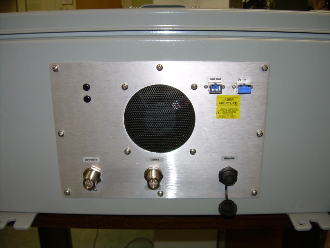
Q4VFS31-15C
Jun 04, 2012Booster
Equipment Class
TNB - Licensed Non-Broadcast Station Transmitter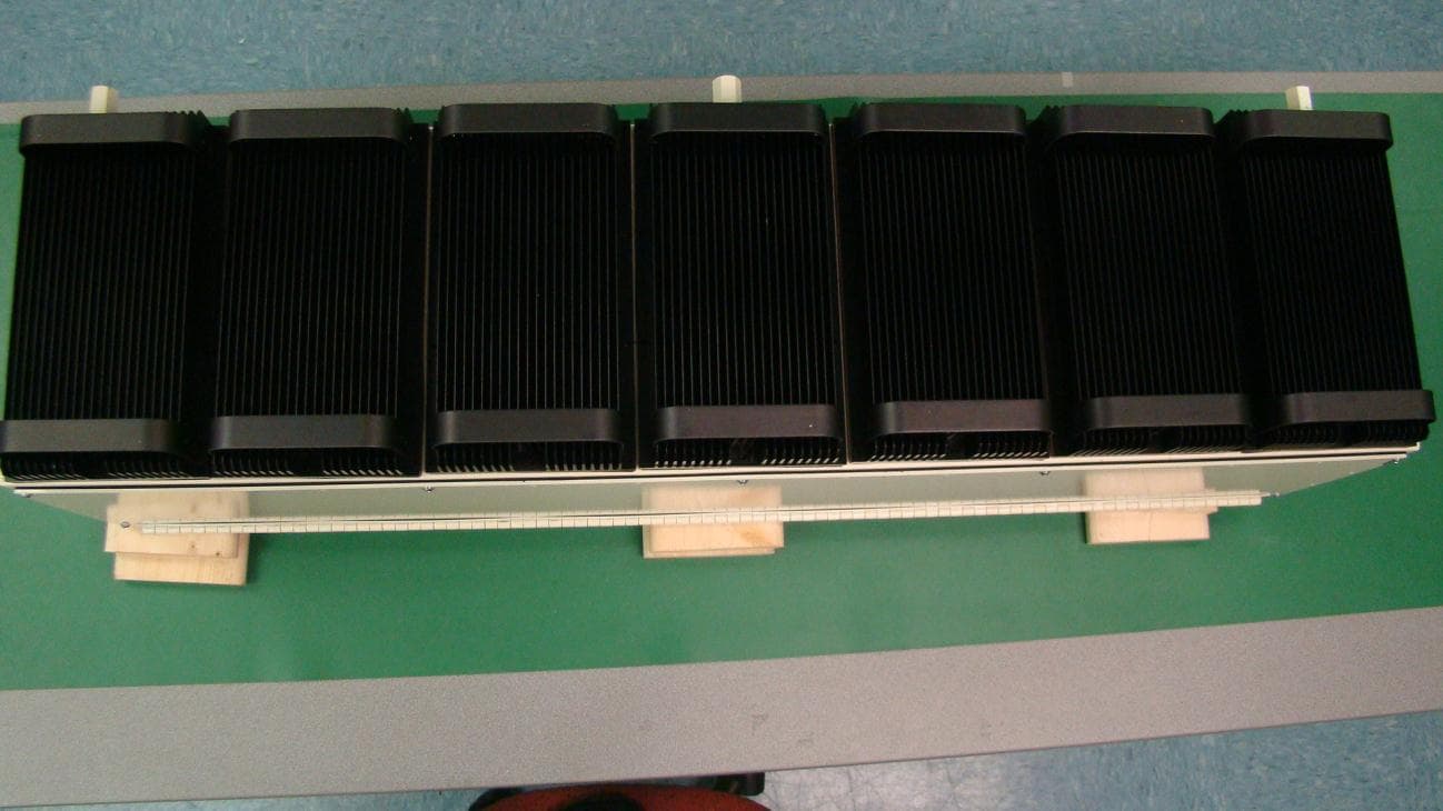
Q4VFS42R-AWS-5
Apr 03, 2011Repeater; Plug-in Service Module, 2.1 GHz AWS Band
Equipment Class
TNB - Licensed Non-Broadcast Station TransmitterQ4VFS45R-CELL-2
Apr 03, 2011Repeater; Plug-in Service Module, 850 MHz Cellular
Equipment Class
TNB - Licensed Non-Broadcast Station Transmitter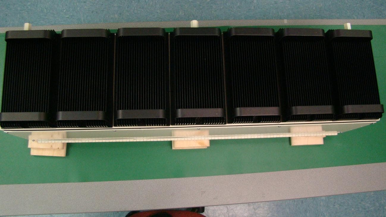
Q4VFS42R-IDEN-2
Apr 03, 2011Repeater; Plug-in Service Module, 800/900 MHz iDen
Equipment Class
TNB - Licensed Non-Broadcast Station Transmitter