Q4VFS31X-19FIBER OPTIC SYSTEM / REPEATER
Fiber-Span LLC
Click to zoom
Application Details
- Equipment Class
- PCB - PCS Licensed Transmitter
- Date of Grant
- Feb 07, 2007
- Application Purpose
- Original Equipment
- Date of Application
- Feb 06, 2007
- Equipment Note
- FIBER OPTIC SYSTEM / REPEATER
- Frequency Range
- 1850.00000000 - 1910.00000000
- Company
- Fiber-Span LLC
- Country
- United States
Documents & Files
Document Text
Text extracted from the exhibit documents filed with the FCC. Open a document above to read the original.
Users Manual
Page 1 of 13 Rev 01 5-DEC-06 Fiber Optic RF Repeater System Fiber-Span Fiber Optic RF Repeater System FS31 Series User Manual Page 2 of 13 Rev 01 5-DEC-06 Fiber Optic RF Repeater System Fiber-Span..........................................................................................................................1 Fiber Optic RF Repeater System......................................................................................1 FS31 Series User Manual ....................................................................................................1 1 Introduction ...................................................................................................................2 2 Warnings.......................................................................................................................2 Warning: Invisible radiation exits from areas labeled “Aperture” .........................................2 3 Product Overview..........................................................................................................3 4 Product Diagrams .........................................................................................................4 5 RF Path Definitions .......................................................................................................6 6 Installation Guide ..........................................................................................................6 6.1 General ..................................................................................................................6 6.2 Fiber Transceiver Unit (FTU) .................................................................................6 6.3 Remote Repeater Unit (RRU) and Integrated Head-end Unit (IHU) ......................7 6.4 Caution ................................................................................................................12 7 Maintenance ...............................................................................................................12 8 Company Information..................................................................................................12 9 Reference Documents ................................................................................................13 1 Introduction This manual outlines the operation and setup for Fiber-Span Fiber Optic Based RF Repeaters. 2 Warnings Figure 1. Laser Warning Label Warning: Invisible radiation exits from areas labeled “Aperture” AC power is used to supply power up the system modules. Use precautions to prevent electrical shock hazards. Always terminate the RF connections before applying power to the unit. Page 3 of 13 Rev 01 5-DEC-06 Fiber Optic RF Repeater System 3 Product Overview Fiber-Span provides product to enable RF signal to be distributed via optical fiber cable. RF signal sources can be used from over the air (OTA) from a Radio Base Station (BS), OTA from handheld devices, or directly from a BS radio. RF signals are converted to modulated light for transport through optical fiber media to remote locations. Modulated light is converted back to the original RF signal where it is processed through filtering and amplification to allow the RF signal to be re-radiated in the remote location. In a bi-directional RF system, the process is the same resulting in remote RF signals that are sent back simultaneously. Fiber-Span product functionality OTA system - RF signals from a remote base station are interchanged usually from a roof top antenna that is connected to an Integrated Head-end Unit (IHU). The IHU receives downlink signals from the base station and sends uplink signals back to the base station. The IHU distributes signals via fiber optics to remote location and also is capable of simultaneously interfacing with a Distributed Antenna System (DAS) for short range RF distribution. Figure 2. Typical OTA Optical RF distribution System Local Base Station System – Signals from a local base station interface to optical distribution equipment through Base Station Units (BSU), or directly to a Fiber Transceiver Unit (FTU). The BSU sometimes interfaces the Base Station to the FTU. The BSU is used to passively condition RF levels or serve as RF filters when applicable. The FTU performs bi-directional optical-RF conversions. Optical signals are sent to the Remote Repeater Unit (RRU). The RRU is designed for use as a remote end of a bi-directional RF distribution system. The RRU RF port works with a direct connected RF antenna or to a Distributed Antenna System (DAS). The RRU is connected via optical fibers to a Fiber Transceiver Unit (FTU) to complete a point to point RF link. IHU RRU Remote Base Station DAS in Building DAS in Building Optical Fiber Page 4 of 13 Rev 01 5-DEC-06 Fiber Optic RF Repeater System Figure 3. Local Base Station System 4 Product Diagrams RRU Block Diagram Line Cord P A P A L L C C H H Power Supply +28V N-F Fiber Transceiver FC/APC FC/APC [Alarm] [RF] [Opt Out] [Opt In] Control Board Power Supply +12V L N A L N A Door Switch Figure 4. Simplified Block Diagram of RRU Optical Fiber BTS BSU FTU RRU RRU RRU RRU Page 5 of 13 Rev 01 5-DEC-06 Fiber Optic RF Repeater System FTU Block Diagram Power Supply Control PCB AC Power Entry Optical In (4) FC/APC Optical Out (4) FC/APC [RF In] [RF Out] Fiber Optic Transceiver Fiber Optic Receiver Optical 4-Way 4-Way RF Combiner N-RF [Opt In 1][Opt In 2][Opt In 3][Opt In 4] [Opt Out 3][Opt Out 2][Opt Out 4][Opt Out 1] [Power] [Laser Alarm] [Receiver 1 Alarm][Receiver 2 Alarm][Receiver 3 Alarm][Receiver 4 Alarm] N-RF [Gain 3] [Opt In Alm 3] [Gain 4] [Opt In Alm 4] [Gain 1] [Opt In Alm 1] [Gain 2] [Opt In Alm 2] [Laser Alm 1] [Summary Alarms] Fiber Optic Receiver Fiber Optic Receiver Optional Figure 5. FTU Block Diagram (4-Way FTU Shown) Page 6 of 13 Rev 01 5-DEC-06 Fiber Optic RF Repeater System 5 RF Path Definitions The RF paths are defined as follows: Downlink – Originates at the FTU or and IHU, over fiber to the RRU to …
Text truncated - open the document above for the full version.
Cover Letter(s)
Page 1 of 1 111 Corporate Blvd. So. Plainfield, NJ 07080 ● Tel 908-754-0646 Fax 908-754-0647 www.fiber-span.com [email protected] 7-Dec-06 Federal Communications Commission, EQUIPMENT APPROVAL SERVICES P. O. Box 358315 Pittsburgh, PA 15251-5315 ATTN: Authorization & Evaluation Division PER: 47 CFR 0.457 and 0.459 RE: Q4VFS31X-19 Pursuant to Sections 0.457(d)(1)(ii) and 0.459 of the Commission's Rules, the Applicant hereby requests confidential treatment of some of the information accompanying this Application as listed below, i.e. Description Number Schematic, Fiber Optic Repeater, 2-Way 275-0001-SCH.pdf Block Diagram, Fiber Optic Repeater, 2-Way 275-0001-BLK.pdf Bill Of Materials for FS31X-4, FS31X-8, and FS31X-X BOMs.pdf FS31X-19X Internal Photos Internal Photos.pdf These materials contain trade secrets and proprietary information not customarily released to the public and the public disclosure of these matters might be harmful to the Applicant and provide unjustified benefits to its competitors. The submitted Fiber optic repeater equipment is designed for Public Safety and Commercial applications which transmit and receive Security and Private information. The equipment is installed in areas that are accessible only by the site security to prevent access to the general public. The hardware contains NO SERVICEABLE PARTS and is the sole responsibility of Fiber-Span or authorized agent to repair or access internal components of this product. The Applicant understands that pursuant to Rule 0.457(d)(1)(ii) disclosure of this Application and all accompanying documentation will not be made before the date of the Grant for this Application. Sincerely, Fiber-Span James Stewart Engineering Manager
External Photos
EXTERNAL PRODUCT PHOTOS FIBER OPTIC REPEATER Fiber-Span 111 Corporate Blvd. (908) 754-0646 So. Plainfield, NJ 07080 Figure 1. Internal Photo Front View. Figure 2. Internal Photo Rear View
ID Label/Location Info
FCC ID: Q4VFS31X-19 IC ID: 6871A-FS31X19 Fiber Optic Repeater This device complies with part 15 of the FCC Rules. Operation is subject to the followingtwo conditions: (1) This device may not cause harmful interference, and (2) this device must acceptanyinterference received,including interferencethatmay cause undesired operation.
ID Label/Location Info
Pin Desc.Function 1N.O. Local Summary Alarm 2Com. 3N.O. Remote 1 Summary Alarm 4Com. 5N.O. Remote 2 Summary Alarm 6Com. 7-- 8-- Dry Contact Normally Open when Status is OK 111 Corporate Blvd. www.fiber-span.com [millimeters] Projection 4U Rackmount Enclosure Integrated Headend Unit Units: inches S. Plainfield, NJ 07080 Fiber-Span Third Angle Outline Drawing 1.50 38.1 18.98 76.2 38.1 482 3.00 1.50 6.95 176.5 Alarms FC/APC Optical In 1& 2 RF N-female Ground Lug 1/4"-20 Thread AC Power Entry IEC 320 Pinout Exhaust Fans Do Not Block Optical Out 1& 2 FC/APC Remote 2 Enable Switch 7 8 1 2 3 4 5 6 Note Key Location Green LED DC Power Off: Fault On: OK Do Not Block Air Intake Typical .406 x .250 Obround Local & Remote Alarms Red LED On: Fault Off: OK 465.1 18.31 482.6 19.00 4.00 101.6 1.4837.5 17.00 431.8 18.00457.2 18.60472.4 FIBER-SPAN RF ON FIBER ® Technology
ID Label/Location Info
16.00406.4 Projection Units: Remote Repeater Unit, Wall-Mount Enclosure www.fiber-span.com S. Plainfield, NJ 07080 111 Corporate Blvd. inches Dwg. No. RRU-0001-OUT Rev:1 [millimeters] Fiber-Span Third Angle Outline Drawing AC Line Cord (1/4"-20 Thread) Alarms Ground Stud N-female RF port FC/APC Optical Out FC/APC Optical In AIR VENTS - DO NOT BLOCK (Top, Bottom, & Side of Unit) 393 15.47 14.00 355.6 8.66 220 6 7 Pin Locations Location 1 2 3 4 5 Note Key 8 Pin Desc.Function 1N.O. Local Summary Alarm 2Com. 3- 4- 5- 6- 7- 8- Dry Contact Normally Open when Status is OK 1/4-Turn Door Latch 304.8 12.00 16.75425.5444.517.50 0 .3 1 T y p . 7 .9 FIBER-SPAN RF ON FIBER ® Technology
Operational Description
Fiber-Span • 111 Corporate Blvd., South Plainfield, New Jersey 07080 Tel: 908-754-0646 • Fax: 908-754-0647 • www.fiber-span.com Features: • Fully Integrated Headend Configuration • Designed Specifically for Off-Air applications • RF Power Options: 1/2, 5, 20 Watt • Low Noise & High Dynamic Range • RF & Alarm Monitoring over same fiber • Support for up to 8 Remote Units. • Battery Back-up Options Integrated Headend Unit, or remote Optical Repeater Applications: •In-building, •Tunnels, •Warehouses, •Parking Garages, •Airports, •Justice Centers, •Manufacturing Facilities •Stadiums, •Convention Centers, •Universities RF ON FIBER ® Signal Distribution products for In-building coverage extension applications. Fiber-Span’s FS31X Series is a first of its kind in the industry to fully integrate the tradi- tional Bi-directional Amplifier (BDA), combining/splitting sub-system, and fiber optic transceivers all into a single wall-mount enclosure. Fiber-Span’s FS31X product line is designed to be the most cost effective Fiber Optic solution for off-air coverage extension applications. This integrated approach is easy to implement and can be configured to support up to 8 Remote Repeater Units (RRU). In addition to the fiber optic interface, all FS31X series Headend units feature separate transmit and receive RF ports for compatibility with conventional coaxial cable Distrib- uted Antenna Systems (DAS). A separate FS31DU duplexer unit is available for applica- tions where transmit and receive signals must be duplexed onto a common coaxial cable distribution system. Each RRU can be configured with a 1/2, 5, or 20 Watt downlink amplifier, giving system designers the flexibility to “size-up” the remote unit for optimum performance over a single antenna distribution system or a network of distributed antennas. FS31X Series Fiber Optic RF Repeaters 1850-1990 MHz DS3107-8-06 v.1 P C S 5 - W at t V e r si o n Fiber-Span • 111 Corporate Blvd., South Plainfield, New Jersey 07080 Tel: 908-754-0646 • Fax: 908-754-0647 • www.fiber-span.com RF Specifications Typical Specs for a 4-port configuration using IHU model: FS31X-1.9-60-4-WM, and RRU model FS31RS-1.9-C-60-WM Frequency Bands 1930-1990 MHz (downlink) 1850-1910 MHz (uplink) Net Link Gain @ 4 dBo optical path loss 90 dB (downlink) 90 dB (uplink) OIP3 RRU: +45 dBm (downlink) IHU: +45 dBm (uplink) AGC IHU: +20 dB (downlink) RRU: +20 dBm (uplink) Gain Adjustment (manual) RRU downlink: 10 dB in 1 dB increments IHU uplink: 20 dB in 2 dB increments Uplink Noise Figure ≤ 10 dB ( @ Max. Gain ) Max. Output Power per CDMA Channel RRU Downlink 1 Carrier: +20 dBm 2 Carriers: +15 dBm 4 Carriers: +11 dBm 8 Carriers: +6 dBm IHU Uplink: 1 Carrier: +20 dBm 2 Carriers: +15 dBm 4 Carriers: +11 dBm 8 Carriers: +6 dBm VSWR <2:1 Spurious Emission -13 dBm Wavelength 1310 nm Laser type DFB (downlink), FP (uplink) Max. Optical Loss 4 dBo Fiber Type Single-Mode 9/125um Connector Type FC/APC Optical Parameters Environmental Operational Temperature Range -5 to +50 deg C Humidity 10 to 95% Electrical IHU RRU AC Power 50/60 Hz, 115-230 VAC Power Consumption <150Watts <150 Watts Alarms Dry Contact Relay Alarms The model numbers and specifications listed above represent the most common system configuration for the PCS band. Consult the factory to receive speci- fication data for configurations not listed, or to receive an application-specific data sheet. Laser Warning: Invisible Laser Radiation emitting from optical connector. Avoid direct exposure to beam. 20 mW max. @ 1300 and 1550 nm. CDRH Class IIIB. Mechanical Specifications IHU (Model: FS31X-1.9-60-4-WM) Dimensions (W x H x D) inches 20 x 16 x 8 Weight <80 lbs. RF Connector Type N-Female RRU (Model: FS31RS-1.9-C-60-WM) 20x 16x 8 < 80 lbs. N-Female RRU - Remote Repeater Unit Number Key: FS31RS-1.9-Z-BB-YY RM=Rack Mount version WM=Wall Mount version (no NEMA rating) 65= Wall Mount IP65 enclosure type 66=Wall Mount IP66 enclosure type 4X=Wall Mount NEMA 4X enclosure type 40=Wall Mount NEMA 4 enclosure type Enclosure Type Bandwidth Selections 05 = 5 MHz Passbands 15 = 15 MHz Passbands 60 = 60 MHz Passbands 1 = 1 TX & RX ports 2 = 2 TX & RX ports 3 = 3 TX & RX ports 4 = 4 TX & RX ports 5 = 5 TX & RX ports 6 = 6 TX & RX ports 7 = 7 TX & RX ports 8 = 8 TX & RX ports # of Fiber Optic Ports IHU - Integrated Headend Unit Number Key: FS31X-1.9-BB-J-YY RM=Rack Mount version WM=Wall Mount version (no NEMA rating) 65= Wall Mount IP65 enclosure type 66=Wall Mount IP66 enclosure type 4X=Wall Mount NEMA 4X enclosure type 40=Wall Mount NEMA 4 enclosure type Enclosure Type 05 = 5 MHz Passbands 15 = 15 MHz Passbands 60 = 60 MHz Passbands Bandwidth Selections A = 1/2 Watt Version C = 5 Watt Version E = 20 Watt Version RF Output Power ORDERING INFORMATION
Parts List/Tune Up Info
Fiber-Span Tune Up Information Page 1 of 1 111 Corporate Blvd. So. Plainfield, NJ 07080 ● Tel 908-754-0646 Fax 908-754-0647 www.fiber-span.com [email protected] 31-Jan-07 Re: Fiber-Span tune up information statement Fiber-Span has designed the submitted fiber optic repeater equipment such that there is no requirement for tune up. RF performance is maintained automatically over optical link losses which are accomplished using Fiber- Span proprietary Optical RF Link technology. Tuning of any type must only be done by Fiber-Span or by a Fiber-Span authorized agent. Sincerely, Fiber-Span James Stewart Engineering Manager
Test Report
Nemko Test Report: 1906RUS1 Applicant: Fiber-Span 111 Corporate Blvd, S. Plainfield, NJ 07080 USA Equipment Under Test: FS31X-1.9-60-2-RM (E.U.T.) In Accordance With: CFR 47, Part 24, Subpart E Broadband PCS Repeaters Tested By: Nemko USA, Inc. 802 N. Kealy Lewisville, TX 75057-3136 TESTED BY: DATE: 10 January 2007 David Light, senior Wireless Engineer APPROVED BY: DATE: 12 January 2007 Kevin Rose, Wireless Engineer Number of Pages: 71 Nemko USA, Inc. CFR 47, PART 24, SUBPART E BROADBAND PCS REPEATERS EQUIPMENT: FS31X-1.9-60-2-RM PROJECT NO.: 1906RUS1 Page 2 of 71 Table of Contents SECTION 1. SUMMARY OF TEST RESULTS 3 SECTION 2. GENERAL EQUIPMENT SPECIFICATION 5 SECTION 3. RF POWER OUTPUT 7 SECTION 4. OCCUPIED BANDWIDTH 8 SECTION 5. SPURIOUS EMISSIONS AT ANTENNA TERMINALS 29 SECTION 6. FIELD STRENGTH OF SPURIOUS 60 SECTION 7. TEST EQUIPMENT LIST 61 ANNEX A - TEST DETAILS 62 ANNEX B - TEST DIAGRAMS 68 Nemko USA, Inc. CFR 47, PART 24, SUBPART E BROADBAND PCS REPEATERS EQUIPMENT: FS31X-1.9-60-2-RM PROJECT NO.: 1906RUS1 Page 3 of 71 Section 1. Summary of Test Results Manufacturer Fiber-Span Model No.: FS31X-1.9-60-2-RM Serial No.: A1937-5-1 General: All measurements are traceable to national standards. These tests were conducted on a sample of the equipment for the purpose of demonstrating compliance with CFR 47, Part 24, Subpart E. New Submission Production Unit Class II Permissive Change Pre-Production Unit THIS TEST REPORT RELATES ONLY TO THE ITEM(S) TESTED. THE FOLLOWING DEVIATIONS FROM, ADDITIONS TO, OR EXCLUSIONS FROM THE TEST SPECIFICATIONS HAVE BEEN MADE. See “ Summary of Test Data”. Nemko USA Inc. authorizes the above named company to reproduce this report provided it is reproduced in its entirety and for use by the company’s employees only. Any use which a third party makes of this report, or any reliance on or decisions to be made based on it, are the responsibility of such third parties. Nemko USA Inc. accepts no responsibility for damages, if any, suffered by any third party as a result of decisions made or actions based on this report. This report applies only to the items tested. Nemko USA, Inc. CFR 47, PART 24, SUBPART E BROADBAND PCS REPEATERS EQUIPMENT: FS31X-1.9-60-2-RM PROJECT NO.: 1906RUS1 Page 4 of 71 Summary Of Test Data NAME OF TEST PARA. NO. SPEC. RESULT RF Power Output 24.232 100W Complies Occupied Bandwidth 2.1049 Input/Output Complies Spurious Emissions at Antenna Terminals 24.238(a) -13 dBm Complies Field Strength of Spurious Emissions 24.238(a) -13 dBm E.I.R.P. Complies Frequency Stability 24.235 NA Footnotes: Nemko USA, Inc. CFR 47, PART 24, SUBPART E BROADBAND PCS REPEATERS EQUIPMENT: FS31X-1.9-60-2-RM PROJECT NO.: 1906RUS1 Page 5 of 71 Section 2. General Equipment Specification Supply Voltage Input: Frequency Bands: Downlink: Block A : 1930 – 1945 MHz Block D : 1945 – 1950 MHz Block B : 1950 – 1965 MHz Block E : 1965 – 1970 MHz Block F : 1970 – 1975 MHz Block C : 1975 – 1990 MHz Frequency Bands: Uplink: Block A : 1850 – 1865 MHz Block B : 1865 – 1870 MHz Block C : 1870 – 1885 MHz Block D : 1885 – 1890 MHz Block E : 1890 – 1895 MHz Block F : 1895 – 1910 MHz CDMA GSM NADC W-CDMA EDGE (F9W) (GXW) (DXW) (F9W) (G7W) Type of Modulation and Designator: System Gain: 43 dB Output Impedance: 50 ohms 0.750 W RF Output (Rated): Uplink 28.8 dBm 0.750 W RF Output (Rated): Downlink 28.8 dBm F1-F1 F1-F2 N/A Frequency Translation: Software Duplexer Fullband Band Selection: Nemko USA, Inc. CFR 47, PART 24, SUBPART E BROADBAND PCS REPEATERS EQUIPMENT: FS31X-1.9-60-2-RM PROJECT NO.: 1906RUS1 Page 6 of 71 Description of EUT Fiber optic bi-directional amplifier operating in the 1900 MHz PCS band System Diagram Nemko USA, Inc. CFR 47, PART 24, SUBPART E BROADBAND PCS REPEATERS EQUIPMENT: FS31X-1.9-60-2-RM PROJECT NO.: 1906RUS1 Page 7 of 71 Section 3. RF Power Output NAME OF TEST: RF Power Output PARA. NO.: 24.232 TESTED BY: David Light DATE: 08 January 2007 Test Results: Complies. Measurement Data: Direction Modulation Output per Channel (dBm) Composite Power (dBm) Composite Power (W) Uplink CDMA 25.3 28.3 0.676 Downlink CDMA 25.6 28.6 0.724 Uplink TDMA 25.6 28.6 0.724 Downlink TDMA 25.8 28.8 0.759 Uplink EDGE 25.3 28.3 0.676 Downlink EDGE 25.4 28.4 0.692 Uplink GSM 25.2 28.2 0.661 Downlink GSM 25.4 28.4 0.692 Uplink W-CDMA 25.4 28.4 0.692 Downlink W-CDMA 25.6 28.6 0.724 Equipment Used: 1036-1082-1469-1604-1064-1082-2071-2072 Measurement Uncertainty: +/- 1.7 dB Temperature: 23 °C Relative Humidity: 35 % Nemko USA, Inc. CFR 47, PART 24, SUBPART E BROADBAND PCS REPEATERS EQUIPMENT: FS31X-1.9-60-2-RM PROJECT NO.: 1906RUS1 Page 8 of 71 Section 4. Occupied Bandwidth NAME OF TEST: Occupied Bandwidth PARA. NO.: 24.238 TESTED BY: David Light DATE: 19 December 2006 Test Results: Complies. Test Data: See attached plot(s). Equipment Used: 1036-1082-1469-1604-1064-1082-1659 Measurement Uncertainty: 1X10 -7 ppm Temperature: 23 °C Relative Humidity: 35 % Nemko USA, Inc. CFR 47, PART 24, SUBPART E BROADBAND PCS REPEATERS EQUIPMENT: FS31X-1.9-60-2-RM PROJECT NO.: 1906RUS1 Page 9 of 71 Test Data – Occupied Bandwidth CDMA - Output 300 kHz/ Ref 40 dBmAtt 40 dB RBW 30 kHz VBW 300 kHz A Offset 32.2 dB LVL * Center 1.88 GHzSpan 3 MHz * SWT 10 ms * * *1 PK VIEW -60 -50 -40 -30 -20 -10 0 10 20 30 40 Date: 19.DEC.2006 15:17:34 Nemko USA, Inc. CFR 47, PART 24, SUBPART E BROADBAND PCS REPEATERS EQUIPMENT: FS31X-1.9-60-2-RM PROJECT NO.: 1906RUS1 Page 10 of 71 Test Data – Occupied Bandwidth CDMA - Input Nemko USA, Inc. CFR 47, PART 24, SUBPART E BROADBAND PCS REPEATERS EQUIPMENT: FS31X-1.9-60-2-RM PROJECT NO.: 1906RUS1 Page 11 of 71 Test Data – Occupied Bandwidth CDMA - Output Ref 40 dBmAtt 40 dB A Offset 32.2 dB LVL 300 kHz/Center 1.96 GHzSpan 3 MHz * * RBW 30 kHz VBW 300 kHz SWT 10 ms * *1 PK VIEW -60 -50 -40 -30 -20 -10 0 10 20 30 40 Date: 19.DEC.2006 15:21:27 Nemko USA, Inc. CFR 47, PART 24, SUBPART E BROADBAND PCS REPEATERS EQUIPMENT: FS31X-1.9-60-2-RM PROJECT NO.: 1906RUS1 Page 12 of 71 Test Data – Occup…
Text truncated - open the document above for the full version.
Contact Information
Applicant
Alfred Boschulte(CEO)
Test Firm
Nemko Dallas, Inc.Michael Cantwell
Technical Specifications
| # | Rule Parts | Frequency Range | Power Output | Emission | Tolerance |
|---|---|---|---|---|---|
| 8 | 24E | 1.85 GHz - 1.91 GHz | 750.00 mW | G7W | Amp |
Other Applications from Fiber-Span LLC

Q4VFS71C-85
Nov 04, 2015Digital Narrowband Class A Signal Booster
Equipment Class
B2I - Part 20 Industrial Booster (CMRS)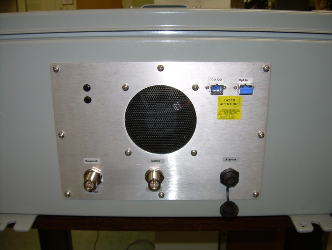
Q4VFS31-15C
Jun 04, 2012Booster
Equipment Class
TNB - Licensed Non-Broadcast Station Transmitter
Q4VFS42R-AWS-5
Apr 03, 2011Repeater; Plug-in Service Module, 2.1 GHz AWS Band
Equipment Class
TNB - Licensed Non-Broadcast Station TransmitterQ4VFS45R-CELL-2
Apr 03, 2011Repeater; Plug-in Service Module, 850 MHz Cellular
Equipment Class
TNB - Licensed Non-Broadcast Station Transmitter
Q4VFS42R-IDEN-2
Apr 03, 2011Repeater; Plug-in Service Module, 800/900 MHz iDen
Equipment Class
TNB - Licensed Non-Broadcast Station Transmitter