Q54URXP01UWB Sensor
S-1 Corporation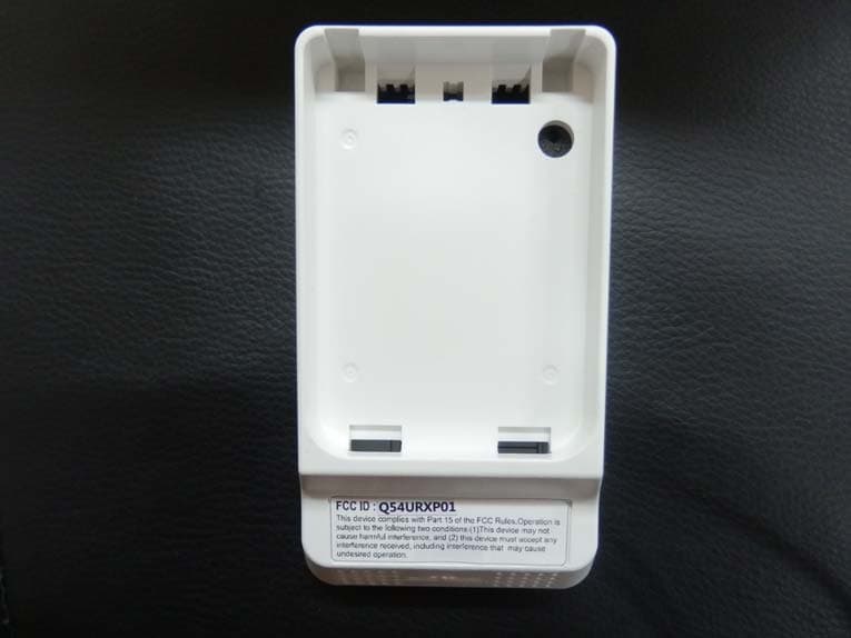
Click to zoom
Application Details
- Equipment Class
- UWB - Ultra Wideband Transmitter
- Date of Grant
- Jul 09, 2015
- Application Purpose
- Original Equipment
- Date of Application
- Jun 01, 2015
- Equipment Note
- UWB Sensor
- Frequency Range
- 8500.00000000 - 9500.00000000
- Company
- S-1 Corporation
- Country
- South Korea
Documents & Files
Document Text
Text extracted from the exhibit documents filed with the FCC. Open a document above to read the original.
Users Manual
Intruder Detector using a radar principle URX-P01 URX-P01-WH [White] URX-P01-BR [Black] Issued Dec 30, 2014 UWB(Ultra Wide Band) refers to a kind of radar technology that was traditionally used in military applications. When used as a security means, it’s low power, wide band characteristics often causes frequent false alarms. Overcoming such limitations with its excellence in technology, S1 showcases the first ever UWB-based security sensor in the world. Its radar-based principle makes it inherently immune to heat source-induced false alarms and enables high level of sensitivity to heat-insulated intruders. Coverage can be flexibly adjusted to enable its deployment in various environments. FEATURES ● Indoor UWB sensor is : • Radar sensor using 9GHz UWB frequency • High detection performance with low false-alarm rate especially in high-temperature variation environments ● Frequency band - from 8.5 GHz to 9.5 GHz ● Max detection range (human target) - to 10 meters ● Adjustable detection range from 1 to 10 meter by rotary switch [Rotary Switch] ☞ Note that each adjusted range has ±0.5m deviation Be sure walk test after installation ● Intruder indicator: • Red LED (ON, OFF selectable by switch) ● Installation – Wall & Ceiling Switch Direction 0 1 2 3 4 5 6 7 8 9 Range 10m 1m 2m 3m 4m 5m 6m 7m 8m 9m Coverage Horizontal View Vertical View 0m(0ft) 0m 1.8m 0ft 2.4m 6ft 3.0m 8ft 10ft 5m(16.4ft) 10m(32.8ft) 2m(6.5ft) Note - Installer is to walk into the pattern or may walk perpendicular to the pattern to verify the pattern. Sensor dimensions NO Name 1 LENS-SENSOR 2 COVER-TOP 3 LAYOUT-MAIN PCB 4 COVER-BOTTOM 5 OUT LABEL-CERTIFICATION 6 LABEL-TERMINAL 7 LABEL-SERIAL UWB Antenna Lens LED GB-41 (Bracket) [SET] Terminal (Power, COM,Tamper) Rotary Switch Label (System) [TOP] [BOTTOM] Label (Certification) Magnetic Switch Point Sensor Specification Model URX-P01 Detection Method Impulse Radio(Ultra Wide Band) Colors URX-P01-WR : White URX-P01-BR : Black Coverage Wide: 8m x 10m(26.24 x 32.80ft), 80 ̊ Wide Mounting Height 2.0 ~ 3.0m(6.5 ~ 10ft) Intruder Speed 0.3 ~ 1.5m/sec.(1 ~ 5ft/sec.) LED Alarm Indicator Red LED ON (When detecting) Tamper Parameters N.C (200VDC 0.1A max.) Alarm Output Period 2 Sec. Alarm Output N.C (60VDC 0.6A max) Warm-up Period Approx. Under 10 sec. Power Supply 12VDC(9.6 ~ 14.4VDC) Current Consumption 20mA (max.) at 12VDC(9.6 ~ 14.4VDC) Weight 85g(2.99oz) Operating Temperature -10°C ~ +50°C(+14°F ~ +122°F) Operating Humidity 95% max. 1. UWB Sensor Bracket specification Model GB-41 Colors White Angle(Default) Horizontal 0 ̊ Vertical 0 ̊ (Do not adjust) Angle(Max range) Horizontal ±50 ̊ Vertical 15 ̊ (Do not adjust) Minimum setting unit Horizontal 5 ̊ Vertical 2.5 ̊ (Do not adjust) Installation Location Wall, Ceiling 2. BRACKET SPECIFICATONS Adjust vertical angle cause reduce detection range. Do not adjust vertical angle Bracket installation 3. BRACKET Install Install ceiling Install wall Wiring connections Combination sensor and Bracket Push hook downwards 4. Remove bracket from sensor Pull sensor forward Bracket installation 5. Adjust Bracket angle Angel adjust Lever Lever position Adjustable Fix Sensor (1EA) Bracket (1EA) Accessories [Bracket] [Black] [White] 6. Sensor components (In unit Box) [Key] 1EA [Screw] Φ4*30L 2EA Sensor installation 2 Step : Assemble “Bottom” and “GB-41” 3 Step : Connection “Top” and “Wire” 1 Step : Using key separate “TOP” and “BOTTOM” SPARE TAMPER ALRAM 12VDC NC C SP NC C (-) (+) Installation 4 Step : Assemble “Top” and “Bottom” Note 1.The unit is to be tested at a min once per year. 2.This unit is designed to detect a burglar or an intruder. When an alarm control panel is activated, the unit detects a burglar or an intruder. It is only a part of a complete system, we cannot responsibility any damage to change without prior consent of the S-1 ※Specifications and design are subject to change without prior notice Installation Notes Operational precautions • Do not apply voltages higher than the rated voltage. AC220V • Do not install where dogs and cats. • When swaying objects(mobiles of metal material), in the detection area, change the direction or adjust the detection distance. • Do not install in the swaying wall. • Do not install the outdoor. • Do not install the curtain(blind) by the external wind swaying. • Do not install near any moving fan.
Users Manual
Intruder Detector using a radar principle URX-P01 User’s Manual Written By Device Development Group S-1 CORPORATION 168, S1 BUILDING, SOONHWA-DONG, JOONG-GU, SEOUL, KOREA Tel: +82 1588 3112 Fax: +82 2 2131 8869 Website: www.s1.co.kr Revised: May 2015 CAUTION!! • This equipment may only be operated Indoors. • Do not use to Outdoors. • Do not intentionally install aimed at windows or outside opening doors. Table of Contents Introduction & Information ....................................................1 Features of the UWB Sensor.................................................2 Coverage of the UWB Sensor...............................................3 UWB Sensor Specifications.................................................4 Installation........................................................................5 Operational precautions......................................................7 INTRODUCTION & INFORMATION Introduction The UWB(Ultra Wide Band) sensors refers to a kind of radar technology that was traditionally used in military applications. When used as a security means, it’s low power, wide band characteristics often causes frequent false alarms. Overcoming such limitations with its excellence in technology, S1 showcases the first ever UWB-based security sensor in the world. Its radar-based principle makes it inherently immune to heat source-induced false alarms and enables high level of sensitivity to the movement of heat-insulated intruders. Coverage can be flexibly adjusted to enable its deployment in various environments. This document describes the features and the specifications of the UWB sensor, important regulatory information concerning its use, and details on how to diagnose potential problems. Information to the User The UWB sensor is an ultra-wideband(UWB) wireless device certified under FCC Part 15.517. It’s use is subject to technical requirements for indoor UWB systems, in particular the stipulation that the devices must only be used indoors. Users should note carefully the following information: • CAUTION: This equipment may only be operated indoors. Operation outdoors is in violation of 47 U.S.C. 301 and could subject the operator to serious penalties. • This device complies with Part 15 of the FCC Rules. Operation is subject to the following two conditions: (1) this device may not cause harmful interference, and (2) this device must accept any interference received, including interference that may cause undesired operation. Users should also carefully note the following information: • CAUTION: Any changes or modifications made to the “UWB Sensor” which are not expressly approved by the “S-1” could void the user’s authority to operate the equipment. • NOTE: This equipment has been tested and found to comply with the limits for a Class B digital device, pursuant to Part 15 of the FCC Rules. These limits are designed to provide reasonable protection against harmful interference in a residential installation This equipment generates, uses and can radiate radio frequency energy and, if not installed and used in accordance with the instructions, may cause harmful interference to radio communications, However, there is no guarantee that interference will not occur in a particular installation. If this equipment does cause harmful interference to radio or television reception, which can be determined by turning the equipment off and on, the user is encouraged to try to correct the interference by one or more of the following measures: - Reorient or relocate the receiving antenna. - Increase the separation between the equipment and receiver. - Connect the equipment into an outlet on a circuit different from that to which the receiver Is connected. - Consult the dealer or an experienced radio/TV technician for help. - 1- UWB Intrusion Detection Sensor – URX-P01 FEATURES OF THE UWB SENSOR UWB Antenna Lens LED GB-41 (Bracket) [SET] Terminal (Power, COM,Tamper) Rotary Switch Label (System) [TOP] [BOTTOM] Magnetic Switch Point Features of the UWB Sensor The diagram below shows several important features of the UWB Sensor: - 2- UWB Intrusion Detection Sensor – URX-P01 COVERAGE OF THE UWB SENSOR Horizontal View Vertical View 0m(0ft) 0m 1.8m 0ft 2.4m 6ft 3.0m 8ft 10ft 5m(16.4ft) 10m(32.8ft) 2m(6.5ft) Note - Installer is to walk into the pattern or may walk perpendicular to the pattern to verify the pattern. Coverage of the UWB Sensor Maximum detection area of the sensor is as follows: -3- UWB Intrusion Detection Sensor – URX-P01 UWB SENSOR SPECIFICATIONS Model URX-P01 Detection Method Impulse Radio(Ultra Wide Band) Colors URX-P01-WR : White URX-P01-BR : Black Coverage Wide: 8m x 10m(26.24 x 32.80ft), 80 ̊ Wide Mounting Height 2.0 ~ 3.0m(6.5 ~ 10ft) Intruder Speed 0.3 ~ 1.5m/sec.(1 ~ 5ft/sec.) LED Alarm Indicator Red LED ON (When detecting) Tamper Parameters N.C (200VDC 0.1A max.) Alarm Output Period 2 Sec. Alarm Output N.C (60VDC 0.6A max) Warm-up Period Approx. Under 10 sec. Power Supply 12VDC(9.6 ~ 14.4VDC) Current Consumption 20mA (max.) at 12VDC(9.6 ~ 14.4VDC) Weight 85g(2.99oz) Operating Temperature -10°C ~ +50°C(+14°F ~ +122°F) Operating Humidity 95% max. UWB Sensor Specifications The specification of the sensor refer to the following table: - 4- UWB Intrusion Detection Sensor – URX-P01 INSTALLATION 2 Step : Assemble “Bottom” and “GB-41” 3 Step : Connection “Top” and “Wire” 1 Step : Using key separate “TOP” and “BOTTOM” SPARE TAMPER ALRAM 12VDC NC C SP NC C (-) (+) - 5- UWB Intrusion Detection Sensor – URX-P01 INSTALLATION 4 Step : Assemble “Top” and “Bottom” Note 1.The unit is to be tested at a min once per year. 2.This unit is designed to detect a burglar or an intruder. When an alarm control panel is activated, the unit detects a burglar or an intruder. It is only a part of a complete system, we cannot responsibility any damage to change without prior consent of the S-1 ※Specifications and design are subject to change without prior notice - 6- UWB Intrusion Detection S…
Text truncated - open the document above for the full version.
Cover Letter(s)
Office of Engineering Technology Federal Communications Commission 7435 Oakland Mills Road Columbia, MD 21046 Date: May 28, 2015 Subject; Request for Confidentiality FCC ID: Q54URXP01 To Whom It May Concern, Pursuant to the provisions of Sections 0.457 and 0.459 of Commission's rules (47CFR0.457, 0.459), we are requesting the Commission to withhold the following attachment(s) as confidential document from public disclosure indefinitely. • Schematic Diagram • Block Diagram • Part List • Operational Description Above mentioned document contains detailed system and equipment description are considered as proprietary information in operation of the equipment. The public disclosure of above documents might be harmful to our company and would give competitor an unfair advantage in the market. In additional to above mentioned documents, pursuant to Public Notice DA 04-1705 of the Commission' s policy, in order to comply with the marketing regulations in 47 CFT §2.803 and the importation rules in 47 CFR §2.1204, while ensuring that business sensitive information remains confidential until the actual marketing of newly authorized devices. We are requesting the commission to grant shot-term confidentiality request on the following attachment(s) for 180 days after the grant as outlined in Public Notice DA 04-1705. • External Photos • Internal Photos • Test Setup Photos • User Manual It is our understanding that all measurement test reports, FCC ID label format and correspondent during certification review process cannot be granted as confidential documents and those information will be available for public review once the grant of equipment authorization is issued. Sincerely, Signature: Name: Cho Choong-Yul Title: Managing Researcher
Cover Letter(s)
Letter of Authorization Company: S1 Coporation Address: 11 th Fl., Samsung Life Insurance & S1 Bldg. 168. Soonhwa-dong, Jung-gu, Seoul, 100-130, South Korea Product Name: UWB Sensor Model Number: URX-P01 FCC Identifier: Q54URXP01 We authorize MiCOM Labs Inc, 575 Boulder Court, Pleasanton, California 94566, USA, to act on our behalf on all matters concerning the above named equipment. Any individual within MiCOM Labs is authorized to act on our behalf and take action on the application. We declare that MiCOM Labs Inc, 575 Boulder Court, Pleasanton, California 94566, USA, is allowed to forward all information related to the approval project to the Federal Communication Commission and to discuss any issues concerning the approval application. Any and all acts carried out by MiCOM Labs on our behalf shall have the same effect as acts of our own. Name: Cho Choong-Yul Date: May 28, 2015 Title: Managing Researcher Signature of applicant:
External Photos
JNDL Laboratory CO., LTD Page 1 of 2 J NDL-QI-TR-F08(0) Report Ref. No. : JNDL-NU-15R-0001 http://www.jndcerti.com FCCID : Q54URXP01 External Photographs 1. Front View 2. Rear View JNDL Laboratory CO., LTD Page 2 of 2 J NDL-QI-TR-F08(0) Report Ref. No. : JNDL-NU-15R-0001 http://www.jndcerti.com FCCID : Q54URXP01 3. Side View (Left) 4. Side View (Right)
ID Label/Location Info
JNDL Laboratory CO., LTD Page 1 of 1 J NDL-QI-TR-F08(0) Report Ref. No. : JNDL-NU-15R-0001 http://www.jndcerti.com FCCID : Q54URXP01 FCC PRODUCT LABELING & WARNING STATEMENT FCC ID Label : Due to the product size, only the FCC ID shall be permanently affixed to the rear side of the equipment and other information shall be placed in the instruction(user’s) manual. FCC WARNING STATEMENT(Including User’s Manual) CAUTION : This equipment may only be operated indoors. Operation outdoors is in violation of 47 U.S.C. 301 and could subject the operator to serious legal penalties. CAUTION : Any changes or modifications made to the “UWB Sensor” which are not expressly approved by the “S-1” could void the user’s authority to operate the equipment. This device complies with part 15 of the FCC Rules. Operation is subject to the following two conditions: (1) This device may not cause harmful interference, and (2) this device must accept any interference received, including interference that may cause undesired operation. FCC ID: Q54URXP01 FCC ID Location
Internal Photos
JNDL Laboratory CO., LTD Page 1 of 6 J NDL-QI-TR-F08(0) Report Ref. No. : JNDL-NU-15R-0001 http://www.jndcerti.com FCCID : Q54URXP01 Internal Photographs 1. Front View 2. Rear View JNDL Laboratory CO., LTD Page 2 of 6 J NDL-QI-TR-F08(0) Report Ref. No. : JNDL-NU-15R-0001 http://www.jndcerti.com FCCID : Q54URXP01 3. Component Board View Top (1) JNDL Laboratory CO., LTD Page 3 of 6 J NDL-QI-TR-F08(0) Report Ref. No. : JNDL-NU-15R-0001 http://www.jndcerti.com FCCID : Q54URXP01 3. Component Board View Top (2) JNDL Laboratory CO., LTD Page 4 of 6 J NDL-QI-TR-F08(0) Report Ref. No. : JNDL-NU-15R-0001 http://www.jndcerti.com FCCID : Q54URXP01 3. Component Board View Top (3) : Antenna Top JNDL Laboratory CO., LTD Page 5 of 6 J NDL-QI-TR-F08(0) Report Ref. No. : JNDL-NU-15R-0001 http://www.jndcerti.com FCCID : Q54URXP01 3. Component Board View Top (4) : Antenna Bottom JNDL Laboratory CO., LTD Page 6 of 6 J NDL-QI-TR-F08(0) Report Ref. No. : JNDL-NU-15R-0001 http://www.jndcerti.com FCCID : Q54URXP01 4. Component Board View Bottom
Test Report
JNDL Laboratory CO., LTD Page 1 of 30 J NDL-QI-TR-F08(0) Report Ref. No. : JNDL-NU-15R-0001 http://www.jndcerti.com FCCID : Q54URXP01 Report No. : JNDL-NU-15R-0001 Client: S1 Corporation Product: UWB Sensor Model: URX-P01 Manufacture/supplier: S1 Corporation Date test item received: 2015/04/10 Date test campaign completed: 2015/05/04 Date of issue: 2015/05/08 Test engineer Report reviewed by Byoung-Su, Shim Gye-Woog, Lee ATTESTATION STAEMENT This equipment has been tested in accordance with the standards identified in the referenced test report. To the best of my knowledge and belief, these tests were performed using the measurement procedures described in this report and demonstrate that the equipment complies with the appropriate standards. All JNDL Laboratory. CO., LTD instrumentation and accessories used to test products for compliance to the indicated standards are calibrated regularly in accordance with ISO 17025 requirements. Total number of pages of this test report : 30 pages CONFORMANCE TEST REPORT FOR Subpart F UWB Part 15.517 JNDL Laboratory CO., LTD Page 2 of 30 J NDL-QI-TR-F08(0) Report Ref. No. : JNDL-NU-15R-0001 http://www.jndcerti.com FCCID : Q54URXP01 REPORT SUMMARY Purpose of Test : To demonstrate the EUT in compliance with FCC Part 15.517 for indoor UWB systems. Disclaimer : The test results relate only to the items tested. Applicable Standards : Pt 15.517, Pt 15.209, ANSI 63.4:2009 TEST ENVIRONMENT AND TEST SETUP Test Facilities : Test Firm Registration # : 748649 3m & 10m Open Site : 386-1, Ho-dong, Cheoin-gu, Yongin-si, Gyeonggi-do, Korea 3m semi-Anechoic chamber : B 114~115, 810 Kwanyang-Dong, dongan- Gu, Anyang-Si, Kyunggi-Do, 431-060, Korea Laboratory Test Conditions : Open Site : Temperature 25 ºC, Humidity : 50 % 3m anechoic chamber : Temperature 24 ºC, Humidity : 46 % Test Exercise : The EUT was set in continuous transmit mode of operation unless stated otherwise. Modification to the EUT : No modification was made. Supporting Accessories : None REVISION HISTORY Revison Date Desriptions 0 2015. 05. 08 Original release JNDL Laboratory CO., LTD Page 3 of 30 J NDL-QI-TR-F08(0) Report Ref. No. : JNDL-NU-15R-0001 http://www.jndcerti.com FCCID : Q54URXP01 Table of Contents 1. General Remarks _______________________________________________________ 4 2. Test Site ______________________________________________________________ 4 2.1 Location ___________________________________________________________ 4 2.2 List of Test equipment used for tests ____________________________________ 4 2.3 Test Date ___________________________________________________________ 4 3. Description of the Equipment Under Test ___________________________________ 5 3.1 Manufacturers declarations ___________________________________________ 5 3.2 Information about UWB intrusion Detection Sensor _______________________ 6 4. List of Measurements ___________________________________________________ 7 5. Transmitter radiated emissions setup _______________________________________ 8 6. Transmitter Characteristics ______________________________________________ 9 7. UWB Bandwidth ______________________________________________________ 10 8. Spurious Radiated Emissions ____________________________________________ 12 9. Radiated Emissions in GPS Bands ________________________________________ 25 10. Peak Emissions within a 50 MHz Bandwidth ______________________________ 28 11. Power Line Conducted ________________________________________________ 30 JNDL Laboratory CO., LTD Page 4 of 30 J NDL-QI-TR-F08(0) Report Ref. No. : JNDL-NU-15R-0001 http://www.jndcerti.com FCCID : Q54URXP01 1. General Remarks The test results in this report apply to the particular Equipment Under Test (EUT) as declared in this report. The test results presented in this report relate only to the item tested. 2. Test Site 2.1 Location JNDL Laboratory. CO., LTD. .(Test Firm Registration # : 748649) 3m anechoic chamber : B 114~115, 810 Kwanyang-Dong, dongan-Gu, Anyang-Si, Kyunggi-Do, Korea 3m & 10m Open site : 386-1, Ho-dong, Cheoin-gu, Yongin-si, Gyeonggi-do, Korea 2.2 List of Test equipment used for tests No. Instrument Model No. Due to Calibration Manufactor Serial No. PSA SPECTRUM ANALYZER (3 Hz ~ 26.5 GHz) E4440A 2016-01-06 Agilent Technologies MY46185375 SPECTRUM ANALYZER (9 KHz ~ 40 GHz) FSP40 2015-10-13 Rohde & Schwarz 100308 SIGNAL GENERATOR (10 MHz ~ 40 GHz) MG3694B 2015-10-15 Anritsu Corp 062513 POWER METER (DC ~ 67 GHz) NRP2 2015-10-14 Rohde & Schwarz 100973 POWER SENSOR (50 MHz ~ 40 GHz) NRP-Z85 2015-10-14 Rohde & Schwarz 101121 POWER SENSOR (9 KHz ~ 6 GHz) NRP-Z92 2015-10-14 Rohde & Schwarz 100093 EMI TEST RECEIVER (9 KHz ~ 7 GHz) ESCI7 2015-07-30 Rohde & Schwarz 100933 EMI TEST RECEIVER (20 MHz ~ 1000 MHz) ESVS30 2015-10-14 Rohde & Schwarz 828525/005 AUTORAING POWER SUPPLY E3630A 2015-10-13 Agilent Technologies MY40005094 BILOG ANTENNA (30 MHz ~ 1000 MHz) VULB 9168 2017-03-15 Schwarzbeck 9168-505 HORN ANTENNA (1 GHz ~ 18 GHz) BBHA 9120D 2016-10-14 Schwarzbeck 568 HORN ANTENNA (1 GHz ~ 18 GHz) 3117 2016-07-24 ETS-Lindgren 00135889 HORN ANTENNA (1 GHz ~ 18 GHz) 3117 2016-07-24 ETS-Lindgren 00135878 HORN ANTENNA (18 GHz ~ 40 GHz) BBHA 9170 2015-09-06 Schwarzbeck BBHA9170440 HORN ANTENNA (18 GHz ~ 40 GHz) BBHA 9170 2015-09-06 Schwarzbeck BBHA9170444 Low Nosie Amplifier (100 MHz ~ 26.5 GHz) TTA2650-HG 2015-05-14 MITEQ 1881352 Low Nosie Amplifier (18 GHz ~ 40 GHz) AMF-6F-18004000-37-8P 2015-10-14 MITEQ 1814914 All equipment is calibrated with traceable calibrations. Each calibration is traceable to the national or international standards. 2.3 Test Date Date of Application: 2015-04 -15 Date of Test: 2015-04-16 ~ 1015-05-04 JNDL Laboratory CO., LTD Page 5 of 30 J NDL-QI-TR-F08(0) Report Ref. No. : JNDL-NU-15R-0001 http://www.jndcerti.com FCCID : Q54URXP01 3. Description of the Equipment Under Test 3.1 Manufacturers declarations Manufacturer : S1 Corporation Product Description : A wireless devices intended to be used for the real-time …
Text truncated - open the document above for the full version.
Test Setup Photos
JNDL Laboratory CO., LTD Page 1 of 10 J NDL-QI-TR-F08(0) Report Ref. No. : JNDL-NU-15R-0001 http://www.jndcerti.com FCCID : Q54URXP01 Test Setup Photographs Photograph 1: Test Setup for 30 MHz ~ 1 GHz EUT X-Y SCAN EUT Z-X SCAN JNDL Laboratory CO., LTD Page 2 of 10 J NDL-QI-TR-F08(0) Report Ref. No. : JNDL-NU-15R-0001 http://www.jndcerti.com FCCID : Q54URXP01 EUT Y-Z SCAN JNDL Laboratory CO., LTD Page 3 of 10 J NDL-QI-TR-F08(0) Report Ref. No. : JNDL-NU-15R-0001 http://www.jndcerti.com FCCID : Q54URXP01 Photograph 2: Test Setup for 1 GHz ~ 18 GHz EUT X-Y SCAN JNDL Laboratory CO., LTD Page 4 of 10 J NDL-QI-TR-F08(0) Report Ref. No. : JNDL-NU-15R-0001 http://www.jndcerti.com FCCID : Q54URXP01 EUT Z-X SCAN JNDL Laboratory CO., LTD Page 5 of 10 J NDL-QI-TR-F08(0) Report Ref. No. : JNDL-NU-15R-0001 http://www.jndcerti.com FCCID : Q54URXP01 EUT Y-Z SCAN JNDL Laboratory CO., LTD Page 6 of 10 J NDL-QI-TR-F08(0) Report Ref. No. : JNDL-NU-15R-0001 http://www.jndcerti.com FCCID : Q54URXP01 TEST MEASUREMENT EQUIPMENT JNDL Laboratory CO., LTD Page 7 of 10 J NDL-QI-TR-F08(0) Report Ref. No. : JNDL-NU-15R-0001 http://www.jndcerti.com FCCID : Q54URXP01 Photograph 3: Test Setup for 18 GHz ~ 40 GHz EUT X-Y SCAN JNDL Laboratory CO., LTD Page 8 of 10 J NDL-QI-TR-F08(0) Report Ref. No. : JNDL-NU-15R-0001 http://www.jndcerti.com FCCID : Q54URXP01 EUT Z-X SCAN JNDL Laboratory CO., LTD Page 9 of 10 J NDL-QI-TR-F08(0) Report Ref. No. : JNDL-NU-15R-0001 http://www.jndcerti.com FCCID : Q54URXP01 EUT Y-Z SCAN JNDL Laboratory CO., LTD Page 10 of 10 J NDL-QI-TR-F08(0) Report Ref. No. : JNDL-NU-15R-0001 http://www.jndcerti.com FCCID : Q54URXP01 TEST MEASUREMENT EQUIPMENT
Contact Information
Applicant
Sun-Ik Cho(Senior Research Engineer)
Technical Contact
Non-Technical Contact
JNDL Laboratory CO, LtdRex Lee
[email protected](81)313822277
Test Firm
JNDL Laboratory Co., LtdRex Lee
Technical Specifications
| # | Rule Parts | Frequency Range | Power Output |
|---|---|---|---|
| 1 | 15F | 8.50 GHz - 9.50 GHz | - |
Other Applications from S-1 Corporation
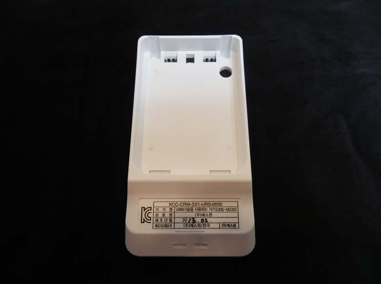
Q54URS0030X
Feb 06, 2014UWB Sensor
Equipment Class
UWB - Ultra Wideband Transmitter
Q54CDR-0130
Oct 27, 2007Smart Card Reader
Equipment Class
DXX - Part 15 Low Power Communication Device Transmitter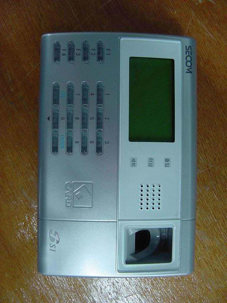
Q54CDR0193X
Oct 26, 2004RF Card & Fingerprint Terminal
Equipment Class
DXX - Part 15 Low Power Communication Device Transmitter
Q54CDR-0191
Mar 03, 2004Fingerprint Attendance & Absence Reader
Equipment Class
DXX - Part 15 Low Power Communication Device Transmitter
Q54CDR-0192
Mar 01, 2004Fingerprint Attendance & Absence Reader
Equipment Class
DXX - Part 15 Low Power Communication Device Transmitter