Q5530XXWireless Payment Reader
ViVOtech, Inc.
Click to zoom
Application Details
- Equipment Class
- DXX - Part 15 Low Power Communication Device Transmitter
- Date of Grant
- Jun 07, 2003
- Application Purpose
- Original Equipment
- Date of Application
- Jun 07, 2003
- Equipment Note
- Wireless Payment Reader
- Frequency Range
- 13.55300000 - 13.56700000
- Company
- ViVOtech, Inc.
- Country
- United States
Documents & Files
Document Text
Text extracted from the exhibit documents filed with the FCC. Open a document above to read the original.
Users Manual
USER GUIDE pay TM 3000 ViVOtech Corporate Headquarters 451 El Camino Real, Santa Clara, CA 95050. Phone: (408) 248 7001 www.vivotech.com TM SM Pr ox i mi t y P a yme nt Solut i o ns TM SM Pr ox i mi t y P a yme nt Solut i o ns Version 1.0April 2003Copyright 2003 ViVOtech, Inc. FCC Regulatory Compliance: Notices Class B Equipment: This equipment has been tested and found to comply with the limits for a Class B digital device, pursuant to part 15 of the FCC Rules. These limits are designed to provide reasonable protection against harmful interference in a residential installation. This equipment generates, uses and can radiate radio frequency energy and, if not installed and used in accordance with the instructions, may cause harmful interference to radio communications. However, there is no guarantee that interference will not occur in a particular installation. If this equipment does cause harmful interference to radio or television reception, which can be determined by turning the equipment off and on, the user is encouraged to try to correct the interference by one or more of the following measures: -- Reorient or relocate the receiving antenna. -- Increase the separation between the equipment and receiver. -- Connect the equipment into an outlet on a circuit different from that to which the receiver is connected. -- Consult the dealer or an experienced radio/TV technician for help.This device complies with part 15 of the FCC Rules. Operation is subject to the following two conditions: (1) This device may not cause harmful interference, and (2) this device must accept any interference received, including interference that may cause undesired operation. ! WARNING: 1.The ViVOpay hardware or software can not be replaced or modified by any third party other than VIVOtech. 2. Minimum separation distance between 2 ViVOpay devices should be at least 2 feet. 3.The device should be mounted and seated on a non metal surface and be at least 6 inches far from any metal surface . ViVOpay 3000 USER GUIDE The ViVOpay is equipped with 4 LEDs on it's translucent cover as well as sound interface to provide consumers feedback on the read process. Upon a successful transaction all 4 LEDs will turn on and a beep will sound to let the customer know that the transaction is completed. Idle: Just first LED is ON Read SUCCESS: all LEDs will be turned on while the module emits a sound acknowledging the success. Read ERROR: If there's an error while reading a card the LEDs will not turn On and no sound will be emitted 3. The ViVOpay quickly reads the information from the card through RF technology - no physical contact is necessary. In a fraction of a second the reader validates the card, and secures the transaction. (As the reader is facing the customer and probably the clerk won't be seeing the LEDs, a beep will let the clerk know that the read was successful). 4. ViVOpay 3000 automatically sends the information to the POS, which processes it as a conventional magnetic stripe card, though with increased security. (Besides mentioning contactless payments and pointing to the ViVOpay unit no intervention from the clerk is necessary during the entire procedure). 5. The POS terminal prints the receipt, which the clerk gives to the consumer for signature as with any other purchase. Consumers just need to hold their Paypass devices in front of the ViVOpay The merchant operation of the ViVOpay 3000 is very simple and almost entirely automated. Once installed, the clerk's role on the operation of the system is simply to guide new customers to hold their cell phones or plastic cards enabled with a contactless RF chip in front of the Reader Module. The information is automatically transferred to POS system and processed in the same way a standard magnetic card would be. Typical Usage ViVOtech Corporate Headquarters 451 El Camino Real, Santa Clara, CA 95050. Phone: (408) 248 7001 LEDs and Sound How it Works Contactless devices as cell phones and plastic cards are enabled with RF tags that securely release the payment information to the ViVOpay terminals without the need of physical contact with the Point of Sale terminal using contactless technology.The ViVOpay is constantly emitting a magnetic field, when it detects an RF tag in the field it communicates with it and retrieves the payment information. The card information is then transmitted to the POS device via the Dynamic Strip TM or direct serial connection. www.vivotech.com TM SM P r o x i mi t y P a yme n t S olut i on s 1. The customer approaches the clerk with one or more items to purchase. The clerk enters the items into the cash register, and once done, asks the consumer for the form of payment and mentions the contactless payment option by pointing to the ViVOpay. 2. The consumer pulls it's contactless cell phone or plastic card and holds it in front of the ViVOpay.
Cover Letter(s)
. VJVOtechTM Proximity Payment Solutions 1M May 16, 2003 Federal Communications Commission Authorization and Evaluation Division Confidentiality Request regarding application for certification of FCC 10: Q5530XX Pursuant to Sections 0.457 and 0.459 of the Commission's Rules, we hereby request confidential treatment of information accompanying this application as outlined below: . . . Schematics, Block diagram, Technical specification. The above materials contain trade secrets and proprietary information not customarily released to the public. The public disclosure of these materials may be harmful to the applicant and provide unjustified benefits to its competitors. The applicant understands that pursuant to Section 0.457 of the Rules, disclosure of this application and all accompanying documentation will not be made before the date of the Grant for this application. Sincerely I (V-~J=1-11\f\ c>J-..o..Jo,... ~ Rafael A. Molano VP I Product Development 451 EL CAMINO REAL, SANTA CLARA, CA 95050 PH: (408) 248-7001 FAX: (408) 248-7002
External Photos
APPENDIX C - EUT PHOTOGRAPHS EUT – Front View EUT – Rear View EUT – Bottom View Adapter View
ID Label/Location Info
APPENDIX A - FCC PRODUCT LABELING AND WARNING STATEMENT FCC ID Label Specifications : Text is black in color and is left justified. Labels are printed in indelible ink on permanent adhesive backing and shall be affixed at a conspicuous location on the EUT. Proposed Label Location on EUT Bottom Side of EUT/FCC ID Label Proposed Location FCC Warning Statement If the EUT is too small, the FCC statement could be presented in the user manual. Generally, appendix B contains one copy of user manual. The following is one sample of the FCC Statement: “ This device complies with part 15 of the FCC Rules. Operation is subject to the following two conditions: (1) This device may not cause harmful interference, and (2) this device must accept any interference received, including interference that may cause undesired operation.” FCC ID: Q5530XX
Internal Photos
APPENDIX C - EUT INTERNAL PHOTOGRAPHS Transceiver Board and Housing 1 Transceiver Board and Housing 2 Transceiver Board Component View Transceiver Board Solder View 1 Transceiver Board Solder View 2 300-1018 Antenna and Housing 300-1018 Antenna Front View 300-1018 Antenna Rear View 300-1019 Antenna Front View 300-1019 Antenna Rear View
Test Report
Note: This test report is specially limited to the above client company and product model only. It may not be duplicated without prior written consent of Bay Area Compliance Laboratory Corporation. This report must not be used by the client to claim product endorsement by NVLAP or any agency of the U.S. Government. FCC ID PER PART 15.225 EMI MEASUREMENT AND TEST REPORT For ViVOtech, Inc. 451 El Camino Real, Santa Clara, CA 95050 FCC ID: Q5530XX 2003-05-22 This Report Concerns: Original Report Equipment Type: Wireless Payment Reader Test Engineer: Benjamin Jin Report Number: R0305131 Test Date: 2003-05-14 Reviewed By: Hans Mellberg Prepared By: Bay Area Compliance Laboratory Corporation 230 Commercial Street Sunnyvale, CA 94085 Tel: (408) 732-9162 Fax: (408) 732-9164 ViVOtech, Inc. FCC ID: Q5530XX Report # R0305131Rpt.doc Page 2 of 16 FCC ID Per 15.225 Report TABLE OF CONTENTS 1 - GENERAL INFORMATION..................................................................................................................................3 1.1 PRODUCT DESCRIPTION FOR EQUIPMENT UNDER TEST (EUT) ..............................................................................3 1.2 OBJECTIVE.............................................................................................................................................................3 1.3 RELATED SUBMITTAL(S)/GRANT(S).......................................................................................................................3 1.4 TEST METHODOLOGY............................................................................................................................................3 1.5 TEST FACILITY.......................................................................................................................................................3 1.6 TEST EQUIPMENT LIST...........................................................................................................................................4 2 - SYSTEM TEST CONFIGURATION.....................................................................................................................5 2.1 JUSTIFICATION.......................................................................................................................................................5 2.2 EUT EXERCISE SOFTWARE....................................................................................................................................5 2.3 SPECIAL ACCESSORIES...........................................................................................................................................5 2.4 SCHEMATICS AND BLOCK DIAGRAM......................................................................................................................5 2.5 EQUIPMENT MODIFICATIONS.................................................................................................................................5 2.6 TEST SETUP CONFIGURATION................................................................................................................................6 2.7 TEST SETUP BLOCK DIAGRAM...............................................................................................................................6 3 - SUMMARY OF TEST RESULTS..........................................................................................................................7 4 - CONDUCTED EMISSIONS TEST ........................................................................................................................8 4.1 MEASUREMENT UNCERTAINTY..............................................................................................................................8 4.2 EUT SETUP............................................................................................................................................................8 4.3 SPECTRUM ANALYZER SETUP................................................................................................................................8 4.4 TEST PROCEDURE..................................................................................................................................................9 4.5 SUMMARY OF TEST RESULTS.................................................................................................................................9 4.6 CONDUCTED EMISSIONS TEST DATA.....................................................................................................................9 4.7 PLOT OF CONDUCTED EMISSIONS TEST DATA.......................................................................................................9 5 - RADIATED EMISSION TEST ............................................................................................................................12 5.1 MEASUREMENT UNCERTAINTY............................................................................................................................12 5.2 EUT SETUP..........................................................................................................................................................12 5.3 SPECTRUM ANALYZER SETUP..............................................................................................................................12 5.4 TEST PROCEDURE................................................................................................................................................13 5.5 CORRECTED AMPLITUDE & MARGIN CALCULATION...........................................................................................13 5.6 SUMMARY OF TEST RESULTS...............................................................................................................................13 5.7 RADIATED EMISSIONS TEST RESULT DATA.........................................................................................................14 6 - FREQUENCY STABILITY MEASUREMENT .................................................…
Text truncated - open the document above for the full version.
Test Setup Photos
APPENDIX B - TEST SETUP PHOTOGRAPHS Conducted Emission - Front View Conducted Emission - Side View Radiated Emission - Front View Radiated Emission - Rear View
Contact Information
Applicant
Clint Woodworth(Director, of QA and Compliance)
Test Firm
Bay Area Compliance LaboratoryJohn Chan
Technical Specifications
| # | Rule Parts | Frequency Range | Power Output |
|---|---|---|---|
| 1 | 15C | 13.553 MHz - 13.567 MHz | - |
Other Applications from ViVOtech, Inc.
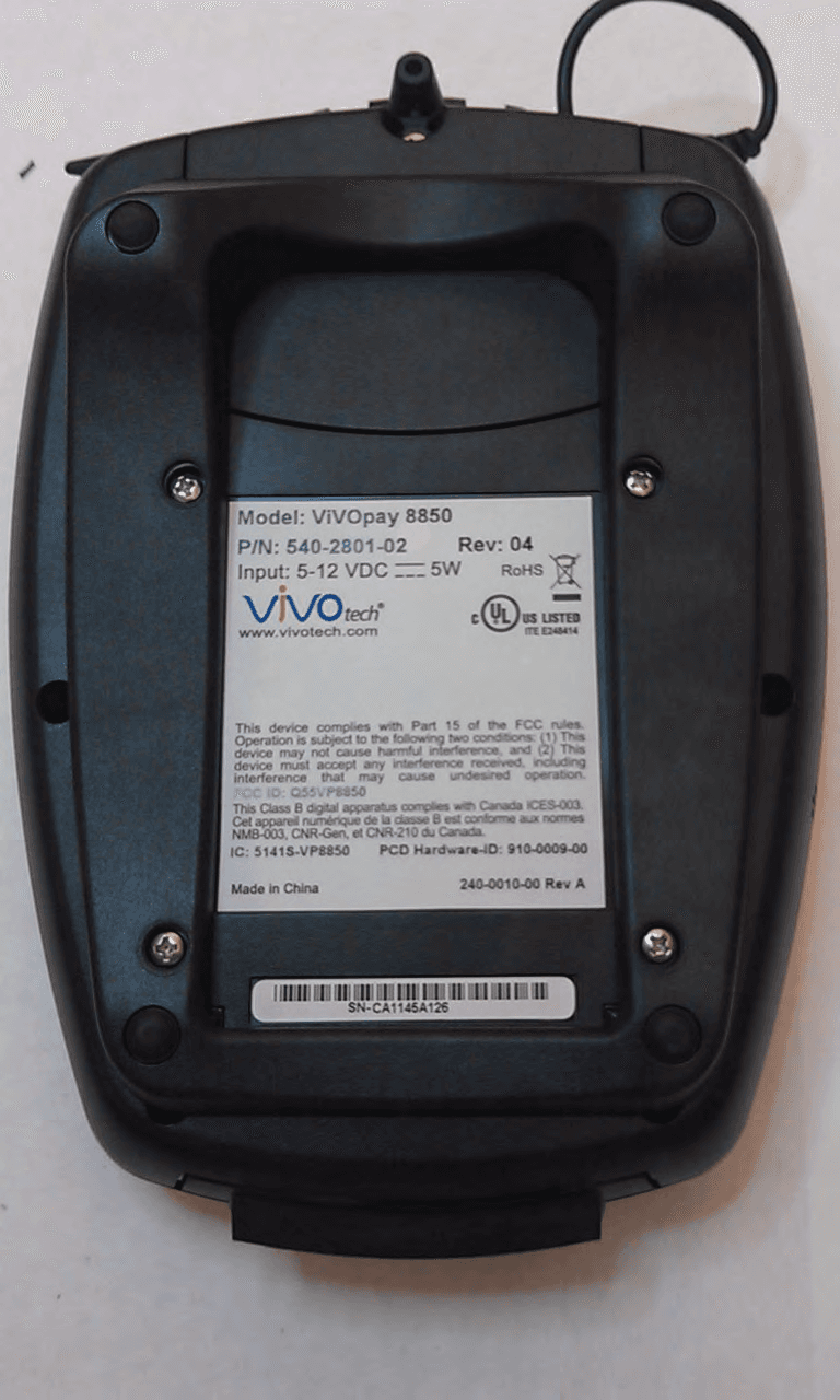
Q55VP8850
Dec 19, 2011Wireless Card Reader
Equipment Class
DXX - Part 15 Low Power Communication Device Transmitter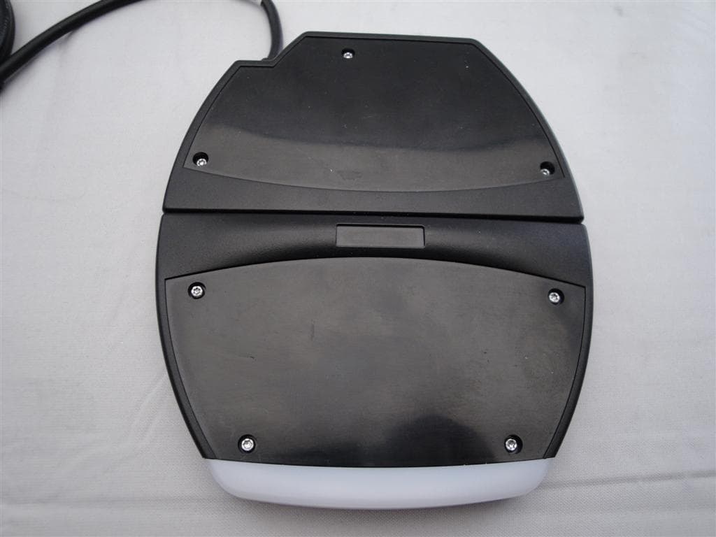
Q55VIVOPAY4800
Aug 15, 2011Wireless Card Reader
Equipment Class
DXX - Part 15 Low Power Communication Device Transmitter
Q55VIVOPAY8100
Aug 15, 2010PCI-PED v2.1 & ISO/IEC14443 Contactless Reader
Equipment Class
DXT - Part 15 Low Power Transceiver, Rx Verified
Q55VP5KAM
Jan 18, 2008Low Power Transmitter Wireless Card Reader
Equipment Class
DXX - Part 15 Low Power Communication Device Transmitter
Q55VIVOPAYKIOSK
Jan 05, 2008Low Power Transmitter Wireless Card Reader
Equipment Class
DXX - Part 15 Low Power Communication Device Transmitter