Q5K60231TR/C Catapult
K&B International Ltd.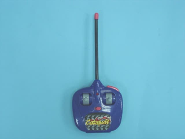
Click to zoom
Application Details
- Equipment Class
- DXX - Part 15 Low Power Communication Device Transmitter
- Date of Grant
- Jul 02, 2007
- Application Purpose
- Original Equipment
- Date of Application
- Jun 19, 2007
- Equipment Note
- R/C Catapult
- Frequency Range
- 27.14500000 - 27.14500000
- Company
- K&B International Ltd.
- Country
- Hong Kong
Documents & Files
Document Text
Text extracted from the exhibit documents filed with the FCC. Open a document above to read the original.
External Photos
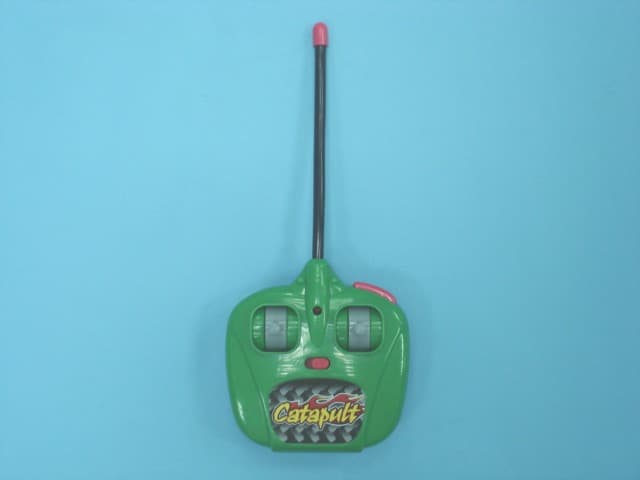
External Photos
ID Label/Location Info
Label and Location
Internal Photos
Internal Photos
Operational Description
Operation Description for R/C Catapult (27MHz) The transmitter for R/C Catapult is powered by 1 x 9V size battery. The radio frequency channel is 27.145MHz. There are two control sticks and one button on the EUT. When the control stick is pushed or the button is pressed, the EUT will transmit different radio control signal to the receiver. Referring to the transmitter circuit design, the circuit description is listed below: - U1 and its associated circuit act as an encoder and a RF amplifier. - Y1 and its associated circuit act as an oscillator. - Q1, D2 and its associated circuit act as a voltage regulator.
Test Report
TEST REPORT Report No. : AJ014003-001 Date : 2007 June 20 Page 1 of 11 FCC ID: Q5K60231T This document shall not be reproduced except in full or with written approval by the laboratory. CMA Industrial Development Foundation Limited Room 1302, Yan Hing Centre, 9-13 Wong Chuk Yeung St.., Fo Tan, Shatin, Hong Kong. Tel: (852) 2698 8198 Fax: (852) 2695 4177 E-mail: [email protected] Web Site: http://www.cmatcl.com Application No. : LJ212111(8) Applicant : K & B Intíl Ltd. Room 406, 4/F., Empire Centre, 68 Mody Road, Tsim Sha Tsui East, Kowloon, Hong Kong Sample Description : One(1) submitted sample(s) stated to be R/C Catapult of Model No. 60231 Radio Frequency : 27.145MHz Transmitter Rating : 1 x 9V size battery No. of submitted sample : One (1) piece(s) *** Date Received : 2007 May 22 Test Period : 2007 May 31 ñ 2007 June 07 Test Requested : FCC Part 15 Certification. Test Method : 47 CFR Part 15 (10-1-05 Edition) ANSI C63.4 ñ 2003 Test Result : See attached sheet(s) from page 2 to 11. Conclusion : The submitted sample was found to comply with requirement of FCC Part 15 Subpart C. For and on behalf of CMA Industrial Development Foundation Limited Authorized Signature : ____________________________________________________ Danny Chui Deputy Manager - EL. Division TEST REPORT Report No. : AJ014003-001 Date : 2007 June 20 Page 2 of 11 FCC ID: Q5K60231T This document shall not be reproduced except in full or with written approval by the laboratory. CMA Industrial Development Foundation Limited Room 1302, Yan Hing Centre, 9-13 Wong Chuk Yeung St.., Fo Tan, Shatin, Hong Kong. Tel: (852) 2698 8198 Fax: (852) 2695 4177 E-mail: [email protected] Web Site: http://www.cmatcl.com Table of Contents 1 General Information .............................................................................................................................3 1.1 General Description .....................................................................................................................3 1.2 Location of the test site ................................................................................................................4 1.3 List of measuring equipment........................................................................................................5 2 Description of the radiated emission test .............................................................................................6 2.1 Test Procedure..............................................................................................................................6 2.2 Test Result....................................................................................................................................6 2.3 Radiated Emission Measurement Data ........................................................................................7 3 Description of the Line-conducted Test...............................................................................................8 3.1 Test Procedure..............................................................................................................................8 3.2 Test Result....................................................................................................................................8 3.3 Graph and Table of Conducted Emission Measurement Data .....................................................8 4 Photograph ...........................................................................................................................................9 4.1 Photographs of the Test Setup for Radiated Emission and Conduction Emission ......................9 4.2 Photographs of the External and Internal Configurations of the EUT.........................................9 5 Supplementary document ...................................................................................................................10 5.1 Bandwidth ..................................................................................................................................10 5.2 Duty cycle ..................................................................................................................................10 5.3 Transmission time ......................................................................................................................10 6 Appendices .........................................................................................................................................11 TEST REPORT Report No. : AJ014003-001 Date : 2007 June 20 Page 3 of 11 FCC ID: Q5K60231T This document shall not be reproduced except in full or with written approval by the laboratory. CMA Industrial Development Foundation Limited Room 1302, Yan Hing Centre, 9-13 Wong Chuk Yeung St.., Fo Tan, Shatin, Hong Kong. Tel: (852) 2698 8198 Fax: (852) 2695 4177 E-mail: [email protected] Web Site: http://www.cmatcl.com 1 General Information 1.1 General Description The equipment under test (EUT) is a transmitter for R/C Catapult. It operates at 27.145MHz and the oscillation of radio control is generated by a crystal. The EUT is powered by 1 x 9V size battery. There are two control sticks and one button on the EUT. When the control stick is pushed or the button is pressed, the EUT will transmit different radio control signal to the receiver. The brief circuit description is listed as follows: - U1 and associated circuit act as an encoder and a RF amplifier. - Y1 and associated circuit act as an oscillator. - Q1, D2 and associated circuit act as a voltage regulator. TEST REPORT Report No. : AJ014003-001 Date : 2007 June 20 Page 4 of 11 FCC ID: Q5K60231T This document shall not be reproduced except in full or with written approval by the laboratory. CMA Industrial Development Foundation Limited Room 1302, Yan Hing Centre, 9-13 Wong Chuk Yeung St.., Fo Tan, Shatin, Hong Kong. Tel: (852) 2698 8198 Fax: (852) 2695 4177 E-mail: [email protected] Web Site: http://www.cmatcl.com 1.2 Location of the test…
Text truncated - open the document above for the full version.
Test Report
Job No. WF-EL-EMC-15 Edition 1 2006 April 12 Page of Bandwidth Plot Bandwidth 1
Test Report
Job No. WF-EL-EMC-15 Edition 1 2006 April 12 Page of Duty Cycle Duty Cycle 1 Duty Cycle 2 Job No. WF-EL-EMC-15 Edition 1 2006 April 12 Page of Duty Cycle Duty Cycle 3
Test Setup Photos
Test Setup Photos
Contact Information
Applicant
Shek Shek(Admin)
Technical Contact
CMA Testing and CertificationDanny Chui
[email protected]852-2690-8251
Rm 1302 Yan Hing Center, 9-13 Wong Chuk Yeung St. · Hong Kong
Test Firm
CMA Industrial Development Foundations LimitedStephen Lam
Technical Specifications
| # | Rule Parts | Frequency Range | Power Output |
|---|---|---|---|
| 1 | 15C | 27.145 MHz - 27.145 MHz | - |
Other Applications from K&B International Ltd.
Q5K60232T
Jul 02, 2007R/C Catapult
Equipment Class
DXX - Part 15 Low Power Communication Device Transmitter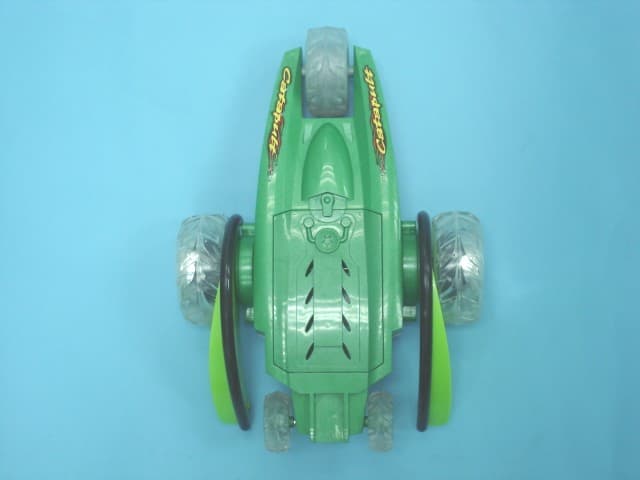
Q5K60232R
Jul 01, 2007R/C Catapult
Equipment Class
CRR - Superregenerative Receiver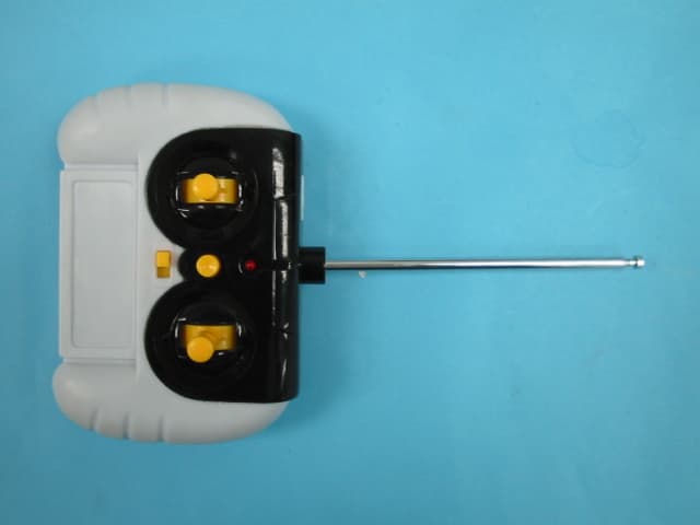
Q5K12609T
May 22, 2007Remote Control Toy Transmitter
Equipment Class
DXX - Part 15 Low Power Communication Device Transmitter
Q5K12609R
May 22, 2007Remote Control Toy Robot
Equipment Class
CRR - Superregenerative Receiver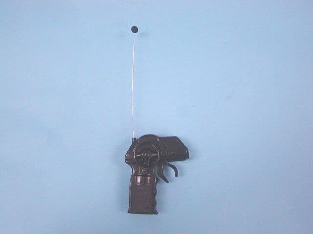
Q5K12847T
May 02, 2007R/C ROBOT ATTACK
Equipment Class
DXX - Part 15 Low Power Communication Device Transmitter