Q5K60232RR/C Catapult
K&B International Ltd.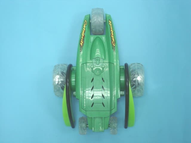
Click to zoom
Application Details
- Equipment Class
- CRR - Superregenerative Receiver
- Date of Grant
- Jul 01, 2007
- Application Purpose
- Original Equipment
- Date of Application
- Jul 01, 2007
- Equipment Note
- R/C Catapult
- Frequency Range
- 49.86000000 - 49.86000000
- Company
- K&B International Ltd.
- Country
- Hong Kong
Documents & Files
Document Text
Text extracted from the exhibit documents filed with the FCC. Open a document above to read the original.
External Photos
External Photos
ID Label/Location Info
Label and Location
Internal Photos
Internal Photos
Test Report
TEST REPORT Report No. : AJ014001-001 Date : 2007 June 20 Page 1 of 11 FCC ID: Q5K60232R This document shall not be reproduced except in full or with written approval by the laboratory. CMA Industrial Development Foundation Limited Room 1302, Yan Hing Centre, 9-13 Wong Chuk Yeung St.., Fo Tan, Shatin, Hong Kong. Tel: (852) 2698 8198 Fax: (852) 2695 4177 E-mail: [email protected] Web Site: http://www.cmatcl.com Application No. : LJ212111(8) Applicant : K & B Intíl Ltd. Room 406, 4/F., Empire Centre, 68 Mody Road, Tsim Sha Tsui East, Kowloon, Hong Kong Sample Description : One(1) submitted sample(s) stated to be R/C Catapult of Model No. 60232 Radio Frequency : 49.860MHz Receiver Rating : 1 x 9.6V rechargeable battery No. of submitted sample : One (1) piece(s) *** Date Received : 2007 May 22 Test Period : 2007 May 31 ñ 2007 June 07 Test Requested : FCC Part 15 Certification. Test Method : 47 CFR Part 15 (10-1-05 Edition) ANSI C63.4 ñ 2003 Test Result : See attached sheet(s) from page 2 to 11. Conclusion : The submitted sample was found to comply with requirement of FCC Part 15 Subpart B. For and on behalf of CMA Industrial Development Foundation Limited Authorized Signature : ____________________________________________________ Danny Chui Deputy Manager - EL. Division TEST REPORT Report No. : AJ014001-001 Date : 2007 June 20 Page 2 of 11 FCC ID: Q5K60232R This document shall not be reproduced except in full or with written approval by the laboratory. CMA Industrial Development Foundation Limited Room 1302, Yan Hing Centre, 9-13 Wong Chuk Yeung St.., Fo Tan, Shatin, Hong Kong. Tel: (852) 2698 8198 Fax: (852) 2695 4177 E-mail: [email protected] Web Site: http://www.cmatcl.com Table of Contents 1 General Information .............................................................................................................................3 1.1 General Description .....................................................................................................................3 1.2 Location of the test site ................................................................................................................4 1.3 List of measuring equipment........................................................................................................5 2 Description of the radiated emission test .............................................................................................6 2.1 Test Procedure..............................................................................................................................6 2.2 Test Result....................................................................................................................................6 2.3 Radiated Emission Measurement Data ........................................................................................7 3 Description of the Line-conducted Test...............................................................................................8 3.1 Test Procedure..............................................................................................................................8 3.2 Test Result....................................................................................................................................8 3.3 Graph and Table of Conducted Emission Measurement Data .....................................................8 4 Photograph ...........................................................................................................................................9 4.1 Photographs of the Test Setup for Radiated Emission and Conduction Emission ......................9 4.2 Photographs of the External and Internal Configurations of the EUT.........................................9 5 Supplementary document ...................................................................................................................10 5.1 Bandwidth ..................................................................................................................................10 5.2 Duty cycle ..................................................................................................................................10 5.3 Transmission time ......................................................................................................................10 6 Appendices .........................................................................................................................................11 TEST REPORT Report No. : AJ014001-001 Date : 2007 June 20 Page 3 of 11 FCC ID: Q5K60232R This document shall not be reproduced except in full or with written approval by the laboratory. CMA Industrial Development Foundation Limited Room 1302, Yan Hing Centre, 9-13 Wong Chuk Yeung St.., Fo Tan, Shatin, Hong Kong. Tel: (852) 2698 8198 Fax: (852) 2695 4177 E-mail: [email protected] Web Site: http://www.cmatcl.com 1 General Information 1.1 General Description The equipment under test (EUT) is a receiver for R/C Catapult. It operates at 49.860MHz and the oscillation of radio control is generated by a LRC circuit. The EUT is powered by 1 x 9.6V rechargeable battery. When it received a forward, backward, turn right, turn left or upside down signal, it will move to the corresponding direction or will make upside down itself. The brief circuit description is listed as follows: - Q1 and associated circuit act as a RF amplifier. - Q2, U1 and associated circuit act as a decoder. - D1 and associated circuit act as a voltage regulator. - Q5, Q6, Q9, D3 and associated circuit act as a motor driver for M1. - Q3, Q4, Q8, D2 and associated circuit act as a motor driver for M2. - D6, D7, Q10 and associated circuit act as a motor driver for M3. TEST REPORT Report No. : AJ014001-001 Date : 2007 June 20 Page 4 of 11 FCC ID: Q5K60232R This document shall not be reproduced except in full or with written approval by the laboratory. CMA Industrial Development Foundation Limited Room 1302, Yan Hing Cen…
Text truncated - open the document above for the full version.
Test Setup Photos
Test Setup Photos
Contact Information
Applicant
Shek Shek(Admin)
Technical Contact
CMA Testing and CertificationDanny Chui
[email protected]852-2690-8251
Rm 1302 Yan Hing Center, 9-13 Wong Chuk Yeung St. · Fo Tan · Hong Kong
Test Firm
CMA Industrial Development Foundations LimitedStephen Lam
Technical Specifications
| # | Rule Parts | Frequency Range | Power Output |
|---|---|---|---|
| 1 | 15B | 49.86 MHz - 49.86 MHz | - |
Other Applications from K&B International Ltd.
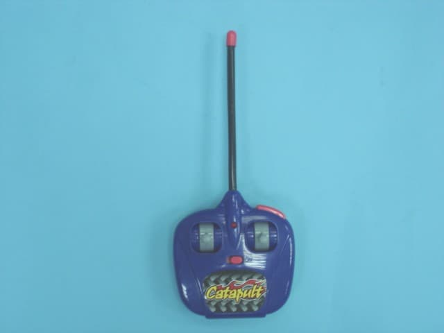
Q5K60231T
Jul 02, 2007R/C Catapult
Equipment Class
DXX - Part 15 Low Power Communication Device Transmitter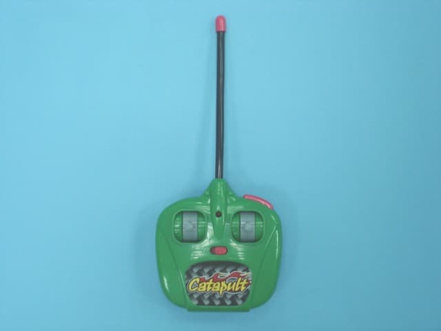
Q5K60232T
Jul 02, 2007R/C Catapult
Equipment Class
DXX - Part 15 Low Power Communication Device Transmitter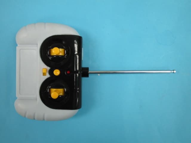
Q5K12609T
May 22, 2007Remote Control Toy Transmitter
Equipment Class
DXX - Part 15 Low Power Communication Device Transmitter
Q5K12609R
May 22, 2007Remote Control Toy Robot
Equipment Class
CRR - Superregenerative Receiver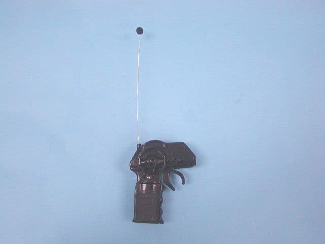
Q5K12847T
May 02, 2007R/C ROBOT ATTACK
Equipment Class
DXX - Part 15 Low Power Communication Device Transmitter