Q639505ASatellite Telephone
Iridium Satellite LLC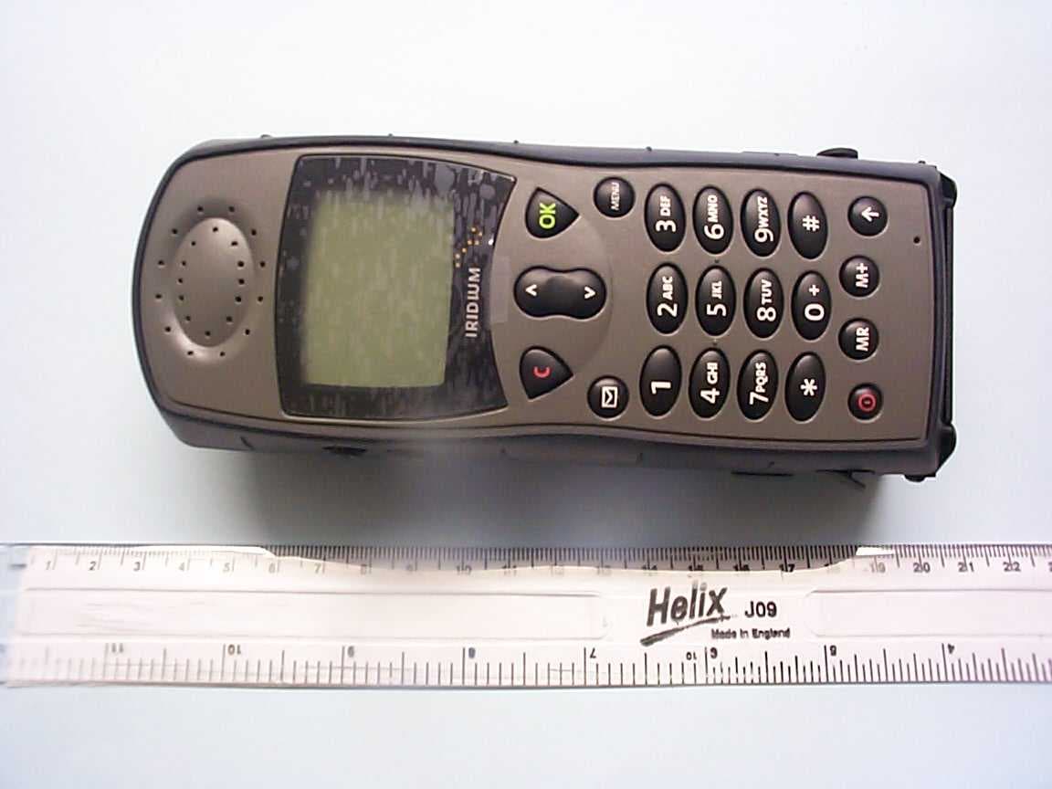
Click to zoom
Application Details
- Equipment Class
- TNE - Licensed Non-Broadcast Transmitter Held to Ear
- Date of Grant
- Nov 10, 2004
- Application Purpose
- Original Equipment
- Date of Application
- Nov 10, 2004
- Equipment Note
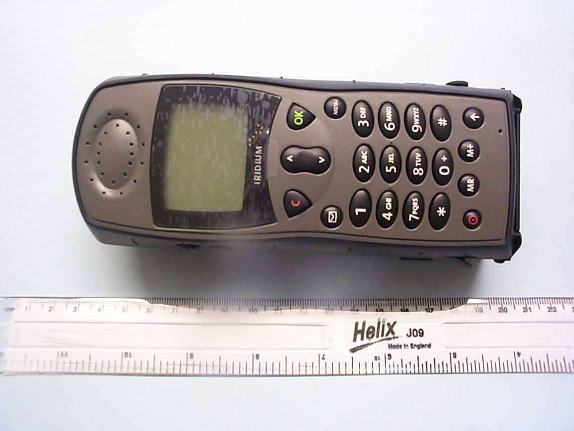
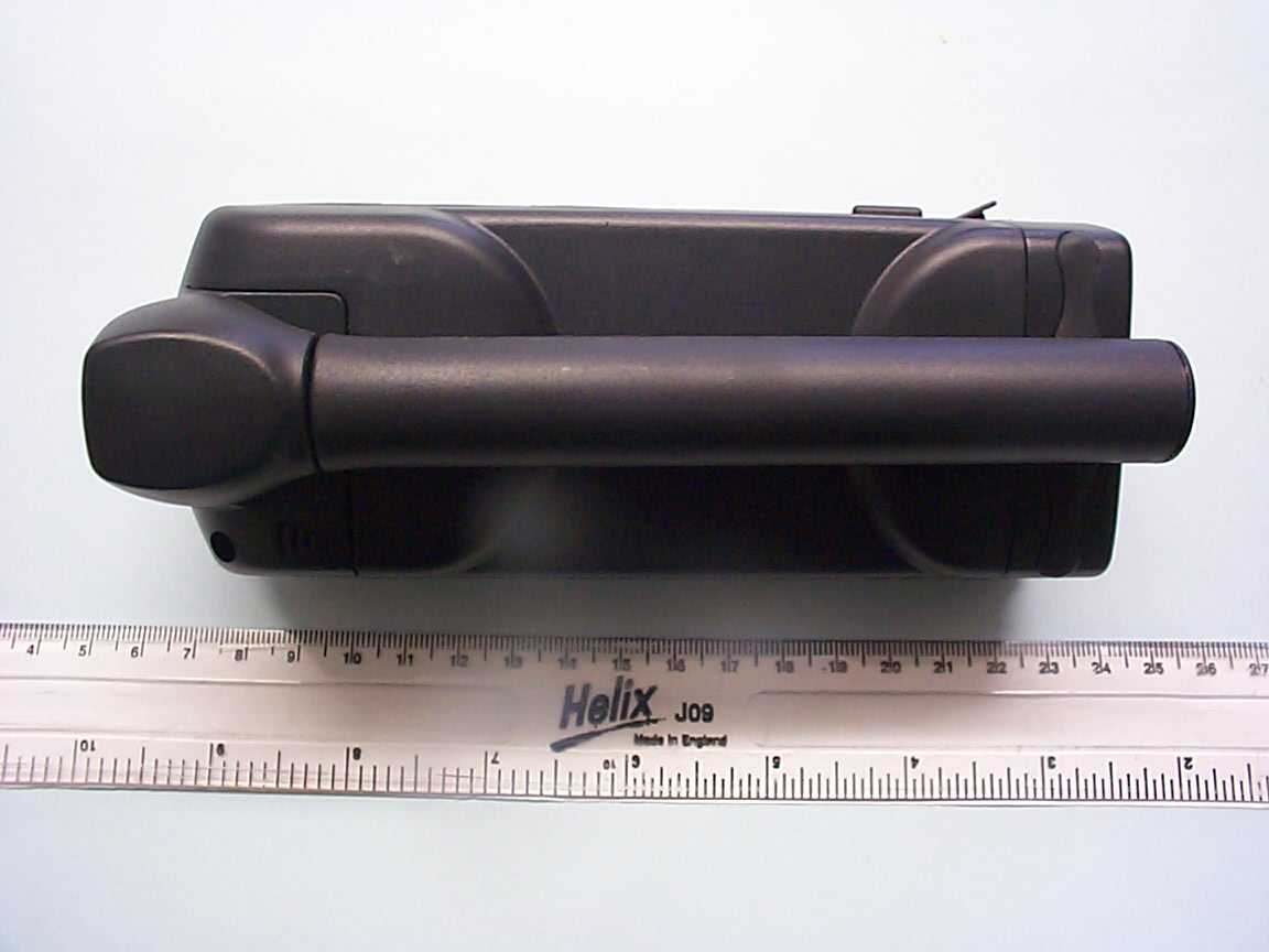
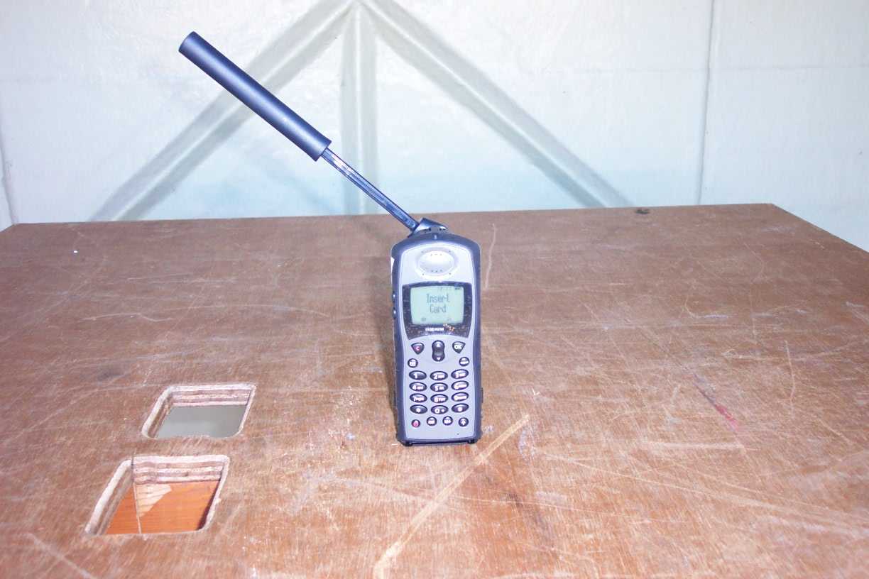
- Satellite Telephone
- Frequency Range
- 1616.00000000 - 1626.50000000
- Company
- Iridium Satellite LLC
- Country
- United States
Documents & Files
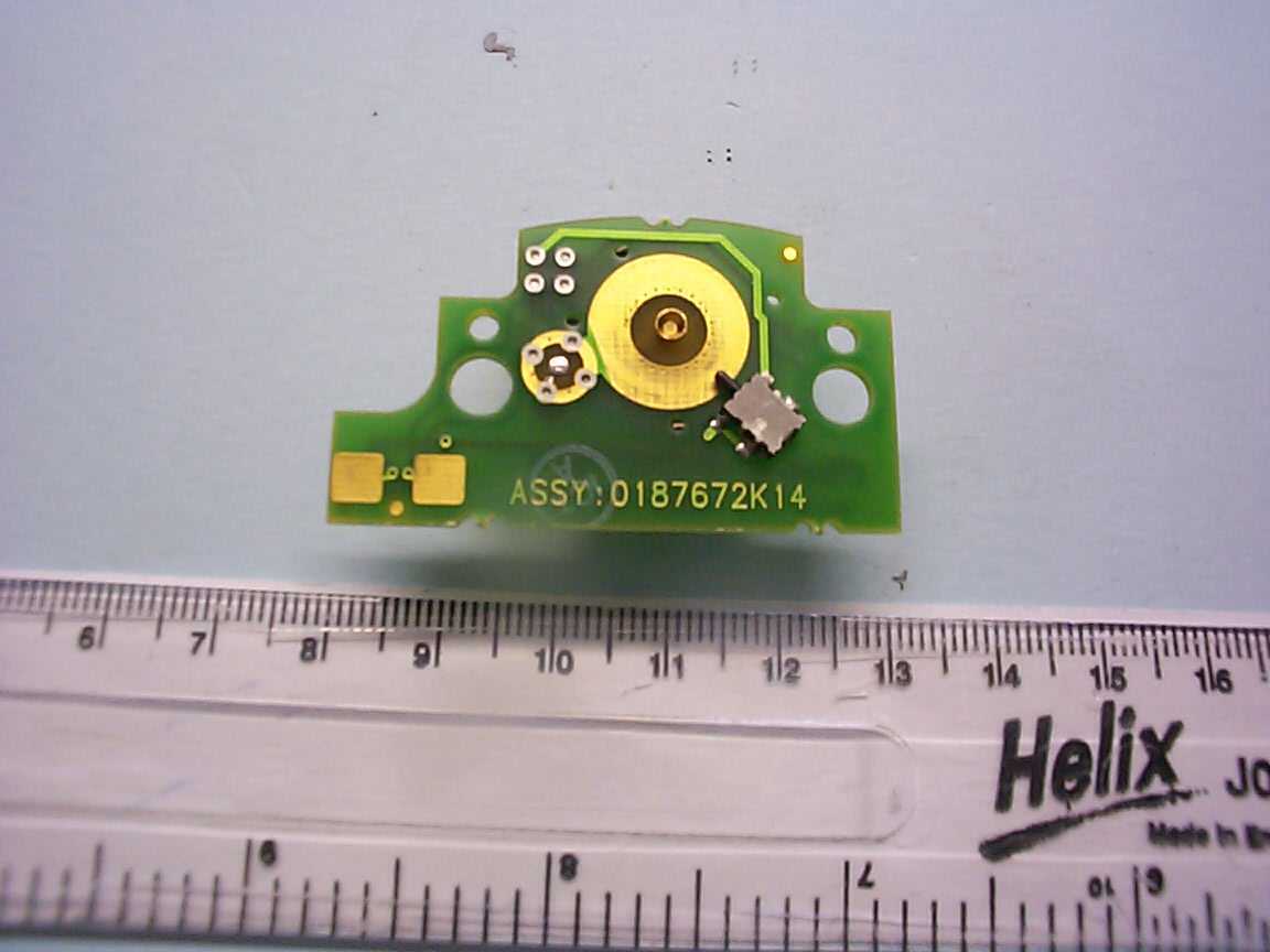
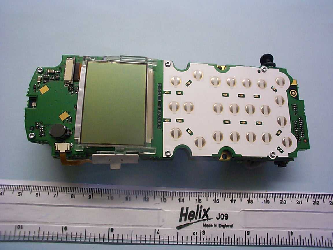
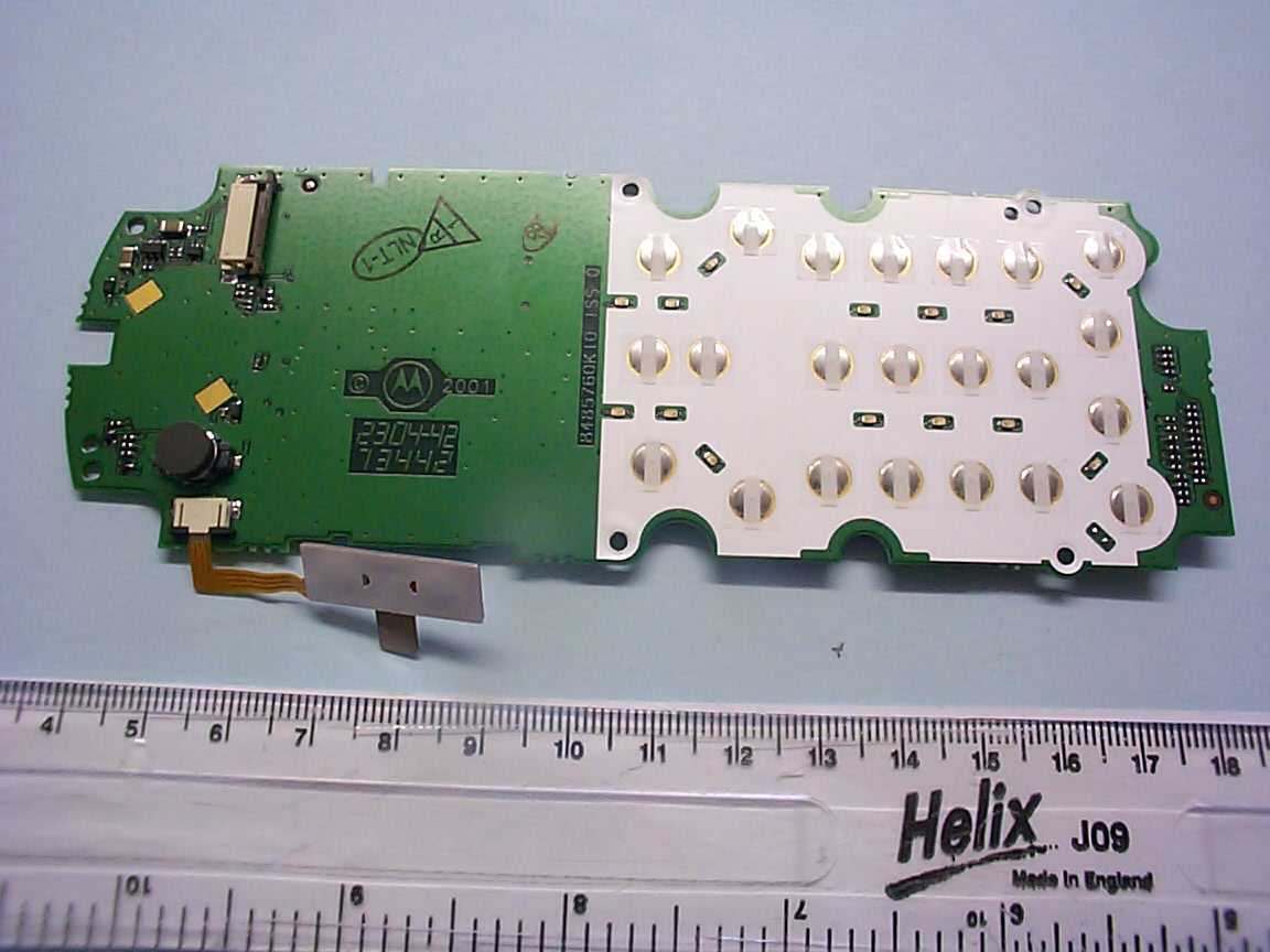
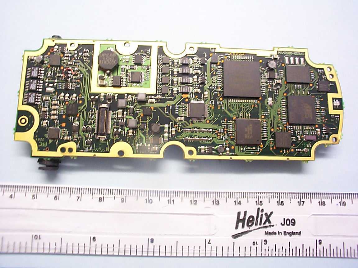
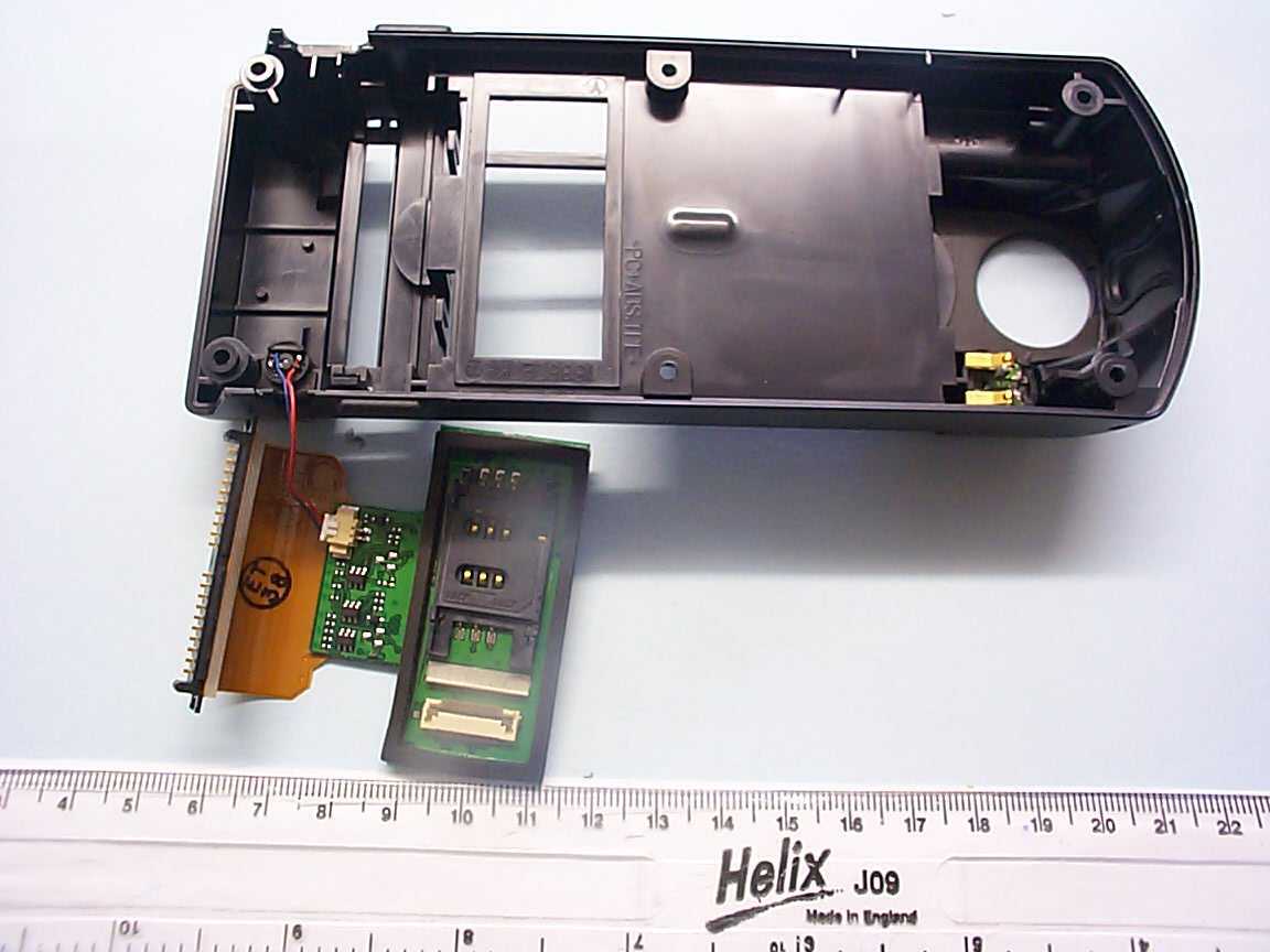
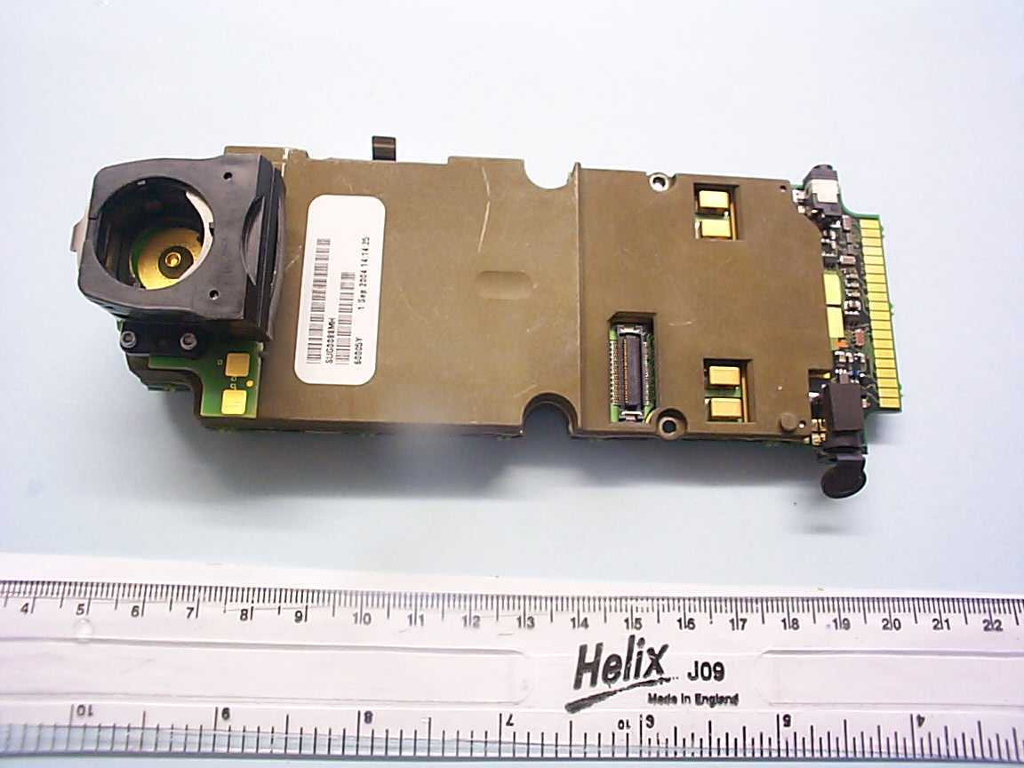
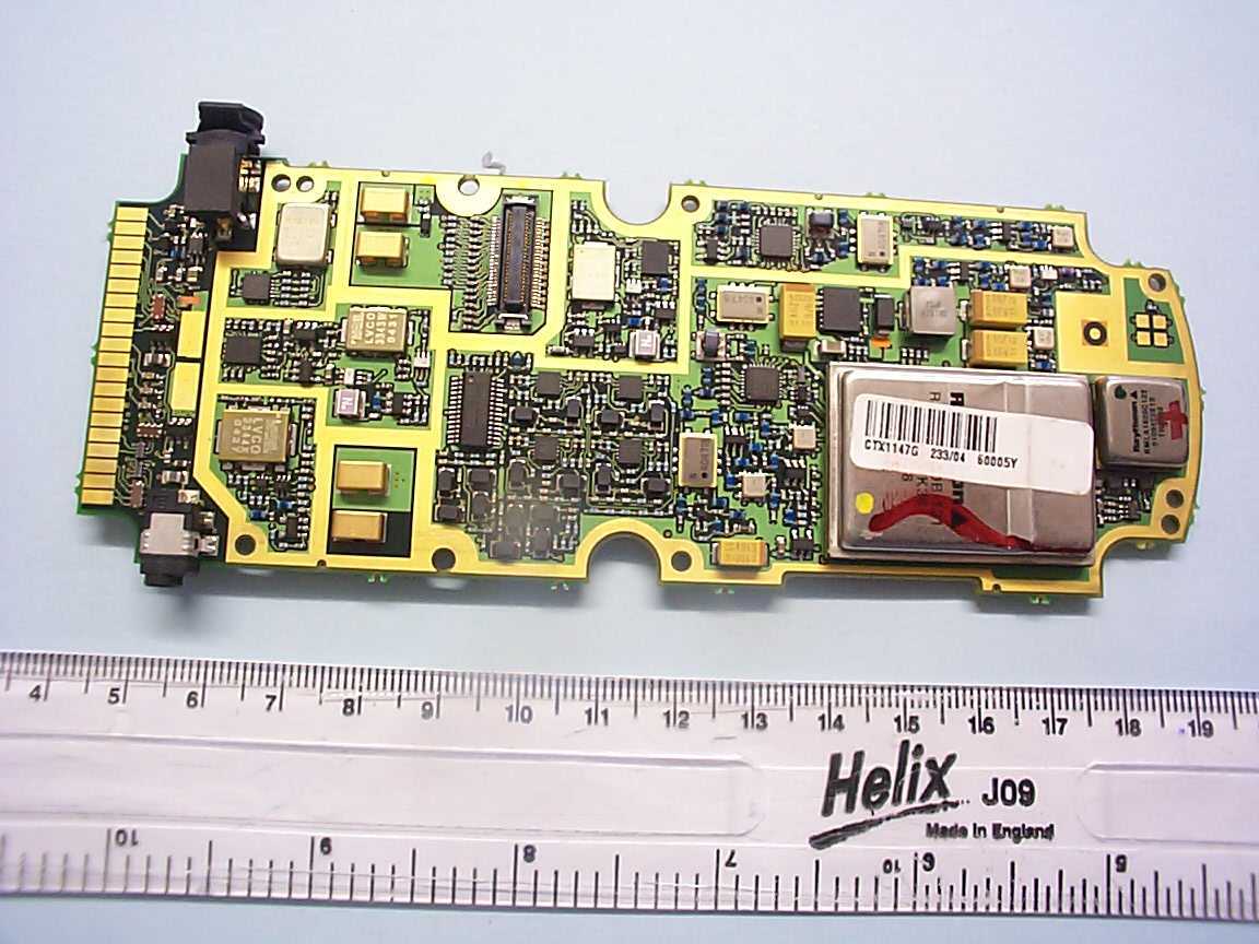
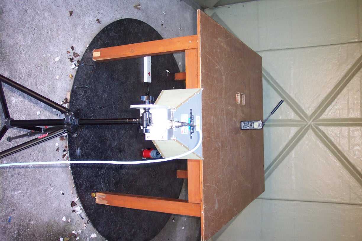
Document Text
Text extracted from the exhibit documents filed with the FCC. Open a document above to read the original.
Users Manual
Adjust Ring Volume Ring or Vibrate Set Ringer Tone Phone Lock Require SIM Card PIN Change SIM PIN2 Code New Security Code Extended Menus Show Time and Date Set Time and Date Set Time Format Language Selection Lights Select Keypad Tones Phone Status Options Menu Quick Reference Show Battery Meter Show Signal Strength Pending Call Drop Call Forwarding Call Waiting Call Barring Call Related Features Show Call Timers Set Audible Call Timers Set In-Call Display Lifetime Timer Call Meters Register Now Network Selection Call Voicemail Received Messages Outgoing Messages Message Editor Message Settings Messages Phone Setup Personal Numbers Show Services Last Ten Calls My Phone Number(s) Fixed Dialing One-Touch Dial Setting Phone Book M Satellite Antenna Lock Release Button Display Microphone Headset Jack Real-Time Clock Battery Charge Indicator Earpiece Signal Strength Indicator Status Indicator Satellite Antenna Volume Control Keys Display and Status Indicators Alphanumeric Keypad Accessory and Power Connector Battery Compartment Connector Message Key Quick Access Key Represents functions not on front of phone. HELPFUL HINTS • Need clear view of sky, outdoors, away from buildings and tall structures. Rotate and fully extend antenna into a vertical position. • Wait until registration is complete (you will see A Registered and the + andn indicators). If no registration (n missing), press E 8 . • To dial, press: [ 0 0 ]or [ 0 and hold for two seconds], [country code], [phone number], O . • Talk with antenna above your head and vertical to the ground. 3. Insert the SIM card.1. Rotate and extend the antenna. 2. Remove battery door.4. Push down and slide the SIM card tray to the right.6. Install the battery by matching arrows on phone and battery. 5. Remove battery ’ s protective cover.7. Attach battery door cover. 8. Attach charging device. Getting Started Display your phone number:Press Q# . Also refer to the “ View Your SIM Card Phone Number(s) ” section of the User ’ s Guide. Special Features Continued 9505 PORTABLE QUICK REFERENCE Find Name 1 E MuteCall VoicemailLock NowBattery Meter Recall a number from the phone book:1. Press Q . 2. Enter the one-, two-, or three-digit location number of the entry, and then press O . 3. Press O to call the displayed entry. Recall last ten numbers dialed:1. Press M until you see Phone Book , and then press O . 2. Press M to scroll to Last Ten Calls , and then press O to select. 3. Press M to scroll to Last Calls Made and then press O to select . 4. Press M to scroll to the number you are looking for. 5. Press O to place a call to that number. Quick Access Menu Phone Book 2345 Vibrate On/OffRead MessagesRegister NowForward On/Off 678 9 Keypad disable:Press * and # keys simultaneously to prevent accidental usage of the phone. All keys with the exception of the S key will be disabled. You can still answer an incoming call by pressing O when the keypad is locked. To remove the keypad disable, press * and # simultaneously. Factory default for satellite mode. Turn the phone's power on/off: Press and hold S . Place a call: You need a clear view of the sky, away from tall structures Rotate and extend the antenna in a vertical position. To dial,press: [ 0 0 ] or [ 0 and hold for two seconds], [country code], [phone number], O . End a call: Press C . Adjust earpiece volume:Press upper and lower volume keys on the side of the phone.Adjust ringer volume:Press E and then the upper and lower volume keys on the side of the phone.Answer a call (with antenna rotated and extended):Phone rings and/or vibratesAfter Call followed by Answer? is in display, press O . Answer a call (with antenna stowed):Phone chirpsRotate and extend antennaPhone will ring and/or vibrateAfter Call followed by Answer? is in display, press O . Clear the last digit in the display or exit a submenu:Press C . Clear the entire display or exit the menu system:Press and hold C . Select prompt language:Press and hold C to return to idle display. Press M 2 6 O to go to the language selection submenu. Press M until you see the preferred language. Press O to select. Basic Operation Special Features (Top) (Top) (Top) ✁ The 9505A Satellite Telephone, working exclusively within the Iridium Satellite Communications System, outperforms other current communications equipment. Designed and manufactured to exacting standards, it is small, light and resistant to water, dust, shock and environmental variables and is ideal for remote areas and rugged conditions. Only Iridium offers complete coverage of the most remote points on earth—oceans, land masses, airways, and even polar regions—and a comprehensive range of mobile and fixed wireless products. No matter where on the globe, your telephone remains in contact at all times and provides a clear signal. Combined with World Satellite Service and World Data Service, the Iridium 9505A Satellite Telephone provides the ultimatesolution to your communications needs. Customize your own package of satellite services, designed for flexible, global coverage, and enjoy your state-of-the-art 9505A Satellite Telephone! Anytime. Anywhere. You have Iridium. ii iii Contents Safety Information. . . . . . . . . . . . . . . . . . . . . . . . .7 Overview . . . . . . . . . . . . . . . . . . . . . . . . . . . . . . .11 Guide Overview . . . . . . . . . . . . . . . . . . . . . . . . .12 Phone Overview . . . . . . . . . . . . . . . . . . . . . . . .13 Indicators . . . . . . . . . . . . . . . . . . . . . . . . . . . . . .16 Accessories . . . . . . . . . . . . . . . . . . . . . . . . . . . .19 Getting Started . . . . . . . . . . . . . . . . . . . . . . . . . .23 Attaching the Satellite Antenna . . . . . . . . . . . . .24 What Is a SIM Card? . . . . . . . . . . . . . . . . . . . . .25 Installing/Removing the SIM Card . . . . . . . . . .26 Removing the Battery Cover . . . . . . . . . . . . . . .28 Installing the Battery . . . . . . . . . . . . . . . . . . . . .29 Removing the Battery . . . . . . . . . .…
Text truncated - open the document above for the full version.
RF Exposure Info
Page 1 of 33 SAR Test Report for FCC and IC Report Number: M040920-2 Test Sample: Celestica Iridium Satellite Phone FCC ID: Q639505A IC: 4629A 9505A Model Number: 9505A Tested For: TRL Compliance Services Date of Issue: 8 th October 2004 EMC Technologies Pty Ltd reports apply only to the specific samples tested under stated test conditions. It is the manufacturer’s responsibility to assure that additional production units of this model are manufactured with identical electrical and mechanical components. EMC Technologies Pty Ltd shall have no liability for any deductions, inferences or generalisations drawn by the client or others from EMC Technologies Pty Ltd issued reports. This report shall not be used to claim, constitute or imply product endorsement by EMC Technologies Pty Ltd. The tests, calibrations or measurements covered by this document have been performed in accordance with NATA requirements, which include the requirements of ISO/IEC 17025 and are traceable to national standards of measurement. This document shall not be reproduced, except in full. The certificate on page 2 may be reproduced in full. NATA Accredited Laboratory Number: 5292 EMC Technologies Pty Ltd ABN 82 057 105 549 57 Assembly Drive Tullamarine Victoria Australia 3043 Ph: + 613 9335 3333 Fax: + 613 9338 9260 email: [email protected] FCC ID: Q639505A IC: 4629A 9505A Report No.: M040920-2 Page 2 of 33 This document must not be copied or reproduced, except in full without the written permission of the Manager, EMC Technologies Pty Ltd. The certificate on page 2 may be reproduced in full. www.emctech.com.au CONTENTS 1.0 General Information ................................................................................................................... 3 2.0 Description of Device................................................................................................................. 4 2.1 Description of Test Sample............................................................................................... 4 2.2 Test sample Accessories .................................................................................................. 4 2.2.1 Battery Types ...................................................................................................................4 2.2.2 Body Worn Position .......................................................................................................... 4 2.3 Test Signal, Frequency and Output Power ....................................................................... 5 2.4 Battery Status ................................................................................................................... 5 2.5 Details of Test Laboratory................................................................................................. 6 2.5.1 Location ............................................................................................................................ 6 2.5.2 Accreditations ................................................................................................................... 6 2.5.3 Environmental Factors...................................................................................................... 6 3.0 Description of SAR Measurement System ............................................................................... 7 3.1 Probe Positioning System................................................................................................. 7 3.2 E-Field Probe Type and Performance............................................................................... 7 3.3 Data Acquisition Electronics ............................................................................................. 7 3.4 Calibration and Validation Procedures and Data .............................................................. 7 3.4.1 Validation Results (1640 MHz) ......................................................................................... 7 3.4.2 Deviation from reference validation values ....................................................................... 8 3.4.3 Liquid Depth 15cm............................................................................................................ 8 3.5 Phantom Properties (Size, Shape, Shell Thickness)......................................................... 8 3.6 Tissue Material Properties ................................................................................................ 9 3.6.1 Liquid Temperature and Humidity ..................................................................................... 9 3.7 Simulated Tissue Composition Used for SAR Test........................................................... 9 3.8 Device Holder for DASY4 ................................................................................................. 9 4.0 SAR Measurement Procedure Using DASY4 ......................................................................... 10 5.0 Measurement Uncertainty ....................................................................................................... 11 6.0 Equipment List and Calibration Details.................................................................................. 13 7.0 SAR Test Method ..................................................................................................................... 14 7.1 Description of the Test Positions .................................................................................... 14 7.1.1 “Touch Position” ............................................................................................................. 14 7.1.2 “Tilted Position”...............................................................................................................14 7.2 List of All Test Cases (Antenna In/Out, Test Frequencies, User Modes) ........................ 14 7.3 FCC RF Exposure Limits for Occupational/ Controlled Exposure ................................... 14 7.4 FCC RF Exposure Limits for U…
Text truncated - open the document above for the full version.
RF Exposure Info
FCC ID: Q639505A IC: 4629A 9505A Report No.: M040920-2 Page 21 of 33 This document must not be copied or reproduced, except in full without the written permission of the Manager, EMC Technologies Pty Ltd. The certificate on page 2 may be reproduced in full. www.emctech.com.au APPENDIX B Plots Of The SAR Measurements Plots of the measured SAR distributions inside the phantom are given in this Appendix for all tested configurations. The spatial peak SAR values were assessed with the procedure described in this report. Table 14: 1600 MHz SAR Plots Plot Number Position Antenna Channel Number Page 1 Touch Right Retracted 120 22 2 Touch Right Extended 120 23 3 Tilted Right Extended 120 24 4 Tilted Right Retracted 000 25 5 Tilted Right Retracted 120 26 6 Tilted Right Retracted 240 27 7 Touch Left Retracted 120 28 8 Touch Left Extended 120 29 9 Tilted Left Retracted 120 30 10 Tilted Left Extended 120 31 Table 15: SAR Validation Plots Plot Number Date Frequency Page 11 24 th September 1640 MHz 32 FCC ID: Q639505A IC: 4629A 9505A Report No.: M040920-2 Page 22 of 33 This document must not be copied or reproduced, except in full without the written permission of the Manager, EMC Technologies Pty Ltd. The certificate on page 2 may be reproduced in full. www.emctech.com.au Test Date: 24 September 2004 File Name: Touch Right 1600 MHz (DAE359 Probe1380) 24-09-04.da4 DUT: Iridium Satellite Phone; Type: SUG0088MBR 9505A; Serial: 600026 * Communication System: 1600 MHz Satellite; Frequency: 1618.25 MHz; Duty Cycle: 1:9.2 * Medium parameters used: σ = 1.2656; mho/m, ε r = 38.5475; ρ = 1000 kg/m 3 - Electronics: DAE3 Sn359; Probe: ET3DV6 - SN1380; ConvF(5.3, 5.3, 5.3) - Phantom: SAM 22; Serial: 1260; Phantom section: Right Section Channel 120 Test/Area Scan (121x51x1): Measurement grid: dx=20mm, dy=20mm Reference Value = 9.19 V/m; Power Drift = -0.5 dB Maximum value of SAR (interpolated) = 0.256 mW/g Channel 120 Test/Area Scan 2 (51x51x1): Measurement grid: dx=20mm, dy=20mm Reference Value = 9.19 V/m; Power Drift = -0.5 dB Maximum value of SAR (interpolated) = 0.264 mW/g Channel 120 Test/Zoom Scan (7x7x7)/Cube 0: Measurement grid: dx=5mm, dy=5mm, dz=5mm Reference Value = 9.19 V/m; Power Drift = -0.5 dB Maximum value of SAR (measured) = 0.248 mW/g Peak SAR (extrapolated) = 0.429 W/kg SAR(1 g) = 0.223 mW/g; SAR(10 g) = 0.151 mW/g 0 dB = 0.248mW/g SAR MEASUREMENT PLOT 1 Ambient Temperature: 20.5 Degrees Celsius Liquid Temperature: 20.0 Degrees Celsius Humidity: 48.0 % FCC ID: Q639505A IC: 4629A 9505A Report No.: M040920-2 Page 23 of 33 This document must not be copied or reproduced, except in full without the written permission of the Manager, EMC Technologies Pty Ltd. The certificate on page 2 may be reproduced in full. www.emctech.com.au Test Date: 24 September 2004 File Name: Touch Right 1600 MHz Extended Antenna (DAE359 Probe1380) 24-09-04.da4 DUT: Iridium Satellite Phone; Type: SUG0088MBR 9505A; Serial: 600026 * Communication System: 1600 MHz Satellite; Frequency: 1618.25 MHz; Duty Cycle: 1:9.2 * Medium parameters used: σ = 1.2656; mho/m, ε r = 38.5475; ρ = 1000 kg/m 3 - Electronics: DAE3 Sn359; Probe: ET3DV6 - SN1380; ConvF(5.3, 5.3, 5.3) - Phantom: SAM 22; Serial: 1260; Phantom section: Right Section Channel 120 Test/Area Scan (121x51x1): Measurement grid: dx=20mm, dy=20mm Reference Value = 2.77 V/m; Power Drift = -0.5 dB Maximum value of SAR (interpolated) = 0.011 mW/g Channel 120 Test/Area Scan 2 (61x61x1): Measurement grid: dx=15mm, dy=15mm Reference Value = 2.77 V/m; Power Drift = -0.5 dB Maximum value of SAR (interpolated) = 0.013 mW/g Channel 120 Test/Zoom Scan (7x7x7)/Cube 1: Measurement grid: dx=5mm, dy=5mm, dz=5mm Reference Value = 2.77 V/m; Power Drift = -0.5 dB Maximum value of SAR (measured) = 0.012 mW/g Peak SAR (extrapolated) = 0.018 W/kg SAR(1 g) = 0.00968 mW/g; SAR(10 g) = 0.0061 mW/g 0 dB = 0.012mW/g SAR MEASUREMENT PLOT 2 Ambient Temperature: 20.5 Degrees Celsius Liquid Temperature: 20.0 Degrees Celsius Humidity: 48.0 % FCC ID: Q639505A IC: 4629A 9505A Report No.: M040920-2 Page 24 of 33 This document must not be copied or reproduced, except in full without the written permission of the Manager, EMC Technologies Pty Ltd. The certificate on page 2 may be reproduced in full. www.emctech.com.au Test Date: 24 September 2004 File Name: Tilted Right 1600 MHz Extended Antenna (DAE359 Probe1380) 24-09-04.da4 DUT: Iridium Satellite Phone; Type: SUG0088MBR 9505A; Serial: 600026 * Communication System: 1600 MHz Satellite; Frequency: 1618.25 MHz; Duty Cycle: 1:9.2 * Medium parameters used: σ = 1.2656; mho/m, ε r = 38.5475; ρ = 1000 kg/m 3 - Electronics: DAE3 Sn359; Probe: ET3DV6 - SN1380; ConvF(5.3, 5.3, 5.3) - Phantom: SAM 22; Serial: 1260; Phantom section: Right Section Channel 120 Test/Area Scan (121x51x1): Measurement grid: dx=20mm, dy=20mm Reference Value = 3.3 V/m; Power Drift = 0.1 dB Maximum value of SAR (interpolated) = 0.016 mW/g Channel 120 Test/Area Scan 2 (61x61x1): Measurement grid: dx=15mm, dy=15mm Reference Value = 3.3 V/m; Power Drift = 0.1 dB Maximum value of SAR (interpolated) = 0.017 mW/g Channel 120 Test/Zoom Scan (7x7x7)/Cube 0: Measurement grid: dx=5mm, dy=5mm, dz=5mm Reference Value = 3.3 V/m; Power Drift = 0.1 dB Maximum value of SAR (measured) = 0.016 mW/g Peak SAR (extrapolated) = 0.030 W/kg SAR(1 g) = 0.015 mW/g; SAR(10 g) = 0.00962 mW/g 0 dB = 0.016mW/g SAR MEASUREMENT PLOT 3 Ambient Temperature: 20.5 deg Celsius Liquid Temperature: 20.0 Degrees Celsius Humidity: 48.0 % FCC ID: Q639505A IC: 4629A 9505A Report No.: M040920-2 Page 25 of 33 This document must not be copied or reproduced, except in full without the written permission of the Manager, EMC Technologies Pty Ltd. The certificate on page 2 may be reproduced in full. www.emctech.com.au Test Date: 24 September 2004 File Name: Tilted Right 1600 MHz (DAE359 Probe1380) 24-09-04.da4 DUT: Iridium Satellite Phone; Type: SUG0088MBR 9505A; Serial: 600026 * Communication System: 1600 MHz Satellite; Frequency: 1610 MHz; Duty…
Text truncated - open the document above for the full version.
Test Report
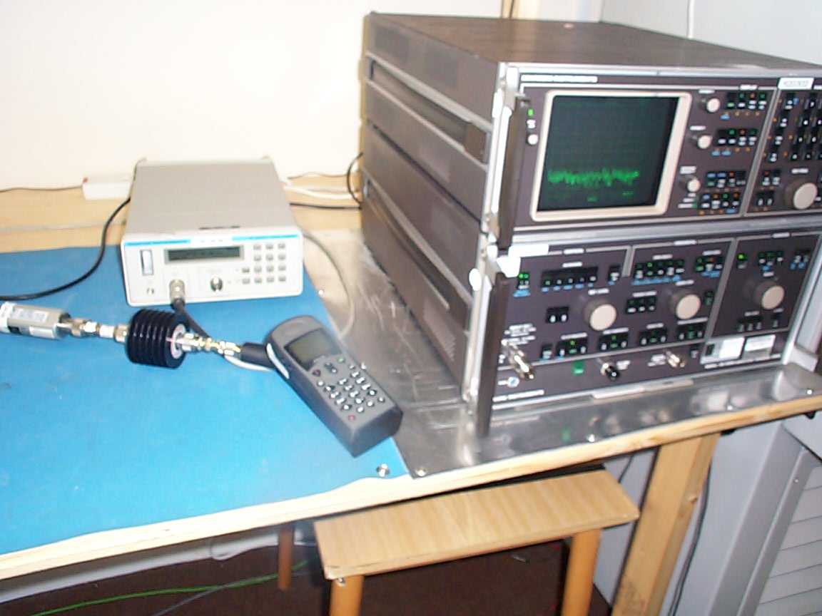
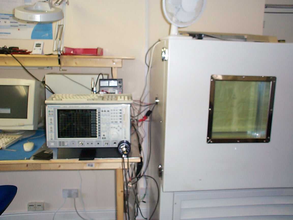
TRL C OMPLIANCE S ERVICES L TD EMC D IVISION L ONG G REEN F ORTHAMPTON G LOUCESTER GL19 4QH U NITED K INGDOM T ELEPHONE +44 (0)1684 833818 F AX +44 (0)1684 833858 E- MAIL [email protected] www.trlcompliance.com FS 21805 TEST REPORT NO: RU1130/5802 COPY NO: 2 ISSUE NO: 1 FCC ID: Q63-9505A REPORT ON THE CERTIFICATION TESTING OF AN IRIDIUM SATELLITE LLC MONACO HANDSET WITH RESPECT TO THE FCC RULES CFR 47, PART 25 TEST DATE: 15 th September 2004 - 17 th September 2004 TESTED BY: J CHARTERS APPROVED BY: P GREEN PRODUCT MANAGER EMC DATE: 8 th October 2004 Distribution: Copy Nos: 1. Cambridge Consultants Limited 2. TCB: TRL Compliance Services Limited 3. TRL EMC THIS DOCUMENT MAY BE REPRODUCED ONLY IN ITS ENTIRETY AND WITHOUT CHANGE RU1130/5802 Page 2 of 46 CONTENTS PAGE CERTIFICATE OF CONFORMITY & COMPLIANCE 3 APPLICANT’S SUMMARY 4 EQUIPMENT TEST CONDITIONS 5 TESTS REQUIRED 5 TEST RESULTS – Transmitter RF Output Power - Conducted 6 Emissions Limitations - Conducted 7 Spurious Emissions - Conducted 8 Spurious Emissions - Radiated 9 Frequency Stability -Temperature 10 Frequency Stability -Voltage 11 ANNEX PHOTOGRAPHS A APPLICANT’S SUBMISSION OF DOCUMENTATION LIST B TEST EQUIPMENT LIST C TEST COMMANDS D DUTY CYCLE E EMISSIONS LIMITATIONS F TRANSMITTER SPURIOUS EMISSIONS – Conducted G TRANSMITTER SPURIOUS EMISSIONS – Radiated H FREQUENCY STABILITY – Temperature I FREQUENCY STABILITY – Voltage J Notes: 1. Component failure during test YES NO [ ] [X] 2. If Yes, details of failure: 3. The facilities used for the testing of the product contain in this report are FCC Listed. RU1130/5802 Page 3 of 46 CERTIFICATE OF CONFORMITY & COMPLIANCE FCC IDENTITY: Q63-9505A PURPOSE OF TEST: CERTIFICATION TEST SPECIFICATION: FCC RULES CFR 47, Part 25 TEST RESULT: Compliant to Specification ITU EMISSIONS DESIGNATOR 41K7Q7W EQUIPMENT UNDER TEST: Monaco Handset EQUIPMENT TYPE: Satellite Telephone MAXIMUM OUTPUT +41.76 dBm, 15.9 W, 11.76 dBW ANTENNA TYPE: Part No: Radiated Antenna Type - C7032-GR082 Conducted Antenna Type - C7032-GR080 CHANNEL SPACING: 41.667 kHz NUMBER OF CHANNELS: 252 MODULATION TYPE: Q7W POWER SOURCE(s): +3.7 Vdc TEST DATE(s): 15 th September 2004 – 17 th September 2004 ORDER No(s): EU2910 APPLICANT: IRIDIUM SATELLITE LLC ADDRESS: 6701 Democracy Blvd. Suite 500 Bethesda United States of America MD 20817 TESTED BY: J CHARTERS APPROVED BY: P GREEN PRODUCT MANAGER EMC RU1130/5802 Page 4 of 46 APPLICANT’S SUMMARY EQUIPMENT UNDER TEST (EUT): MONACO HANDSET EQUIPMENT TYPE: Satellite Telephone PURPOSE OF TEST: CERTIFICATION TEST SPECIFICATION(s): FCC RULES CFR 47, Part 25 TEST RESULT: COMPLIANT Yes No [X] [ ] APPLICANT’S CATEGORY: MANUFACTURER IMPORTER DISTRIBUTOR TEST HOUSE AGENT [X] [ ] [ ] [ ] [ ] APPLICANT’S CONTACT PERSON(s): Mr C Geibel E-mail address: [email protected] APPLICANT: IRIDIUM SATELLITE LLC ADDRESS: 6701 Democracy Blvd. Suite 500 Bethesda United States of America MD 20817 TEL: +1 301 571 6277 FAX: +1 301 571 6250 MANUFACTURER: IRIDIUM SATELLITE LLC DEVELOPMENT AGENT Cambridge Consultants Limited DEVELOPMENT AGENT S CONTACT PERSON(s): Mr P Williams E-mail address: [email protected] ADDRESS: Science Park Milton Road Cambridge CB4 4DW United Kingdom TEL: +44 (0)1223 420024 FAX: +44 (0)1223 423373 EUT(s) COUNTRY OF ORIGIN: United States TEST LABORATORY: TRL EMC UKAS ACCREDITATION No: 0728 TEST DATE(s) 15 th September 2004 – 17 th September 2004 TEST REPORT No: RU1130/5802 RU1130/5802 Page 5 of 46 EQUIPMENT TEST / EXAMINATIONS REQUIRED 1. TEST/EXAMINATION FCC Part 2 FCC Part 25 APPLICABILITY RESULT RF Power Output 25.204 (a) YES PASS Emissions Limitations 25.202 (f) YES PASS Spurious Emissions at Antenna Terminals 2.1051 25.202 (f) 25.213 YES PASS Spurious Emissions Radiated 2.1053 25.202 (f) 25.213 YES PASS Frequency Stability Temperature 2.1055 25.202 (d) YES PASS Frequency Stability Voltage 2.1055 25.202 (d) YES PASS Note: The Monaco handset is subject to FCC Part 25 & Part 2 for FCC Certification for units marketed within the United States. The above tests, as specified in FCC Part 2, with limits as defined in FCC part 25 were performed on the Mobile Ididium Subscriber Unit. 2. Product Use: Satellite Telephone 3. Emission Designator: 41k7Q7W 4. Temperatures: Ambient (Tnom) 18 o C 5. Supply Voltages: Vnom +3.7 Vdc Note: Vnom voltages are as stated above unless otherwise shown on the test report page Single channel [ ] Two channel [ ] 6. Equipment Category: Multi-channel [X] 7. Channel spacing: Narrowband [X] 41.667 kHz Wideband [ ] 8. Test Location TRL Compliance Services Up Holland [X] Long Green [ ] 9. Modifications made during test program No modifications were performed. RU1130/5802 Page 6 of 46 Product Description The Satellite phone consist of an L-Band Transceiver (LBT) capable of simultaneous transmit and receive (duplex) operation covering the frequency range of 1616MHz to 1626.5MHz. The frequency accesses used for duplex channels are organised into sub-bands each of which contains eight frequency accesses. Each sub-band, therefore occupies 333.33 kHz (i.e. 8x41.667kHz). Up to 30 sub-bands containing 240 frequency accesses may be used for duplex channels. Standard References 47 CFR 2 Code of Federal Regulations, Title 47, Part 2, “Frequency allocations and Radio Telemetry Matters; 10-1-03 Edition General Rules and Regulations” 47 CFR 25 Code of Federal Regulations, Title 47, Part 25,”Sattelite Communications” Subpart C, 10-1-03 Edition “Technical Matters” C63.4-2001 American National Standards Institute (ANSI), “Methods of Measurement of Radio Noise Emissions from Low Voltage Electrical and Electronic Equipment in the Range 9 kHz to 40 GHz” RU1130/5802 Page 7 of 46 COMPLIANCE TESTS TRANSMITTER TESTS RF OUTPUT POWER – CONDUCTED – PART 25.204 (a) Ambient temperature = 25 o C Radio Laboratory Relative humidity = 58% Supply voltage = +3.7 Vdc Channel number = See test results See Annex C for full list of test equipment The test setup was as per the abov…
Text truncated - open the document above for the full version.
Contact Information
Applicant
Kathy Morgan(Chief Legal Officer)
Technical Contact
Cambridge Consultants LtdRichard Davies
[email protected]+44 1223 392423
Science Park · Cambridge · United Kingdom
Test Firm
TRL EMC LimitedNeil Roche
Technical Specifications
| # | Rule Parts | Frequency Range | Power Output | Emission | Tolerance |
|---|---|---|---|---|---|
| 1 | 25 | 1.62 GHz - 1.63 GHz | 8 W | 41K7V7E | 1.0000000000 ppm |
Other Applications from Iridium Satellite LLC
Q639604
Apr 09, 2026Hybrid LTE-M Cellular + IRIDIUM Satellite + GNSS module for IoT
Equipment Class
TNB - Licensed Non-Broadcast Station TransmitterQ639704
Dec 08, 2024Data satellite transceiver module for use with the Iridium satellite communications network.
Equipment Class
TNB - Licensed Non-Broadcast Station TransmitterQ639690
Aug 18, 2020Standalone satellite device with Java application programming environment. Includes internal power supply, Iridium Short Burst Data Transceiver, GNSS, BLE, I/O, RS232, RS485, CAN.
Equipment Class
TNB - Licensed Non-Broadcast Station Transmitter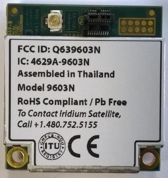
Q639603N
Aug 26, 2014Short Burst Data Transceiver
Equipment Class
JBP - Part 15 Class B Computing Device Peripheral
Q639560
Mar 31, 2014Iridium 9560 Wi-Fi Access Point with satellite transceiver
Equipment Class
DTS - Digital Transmission System