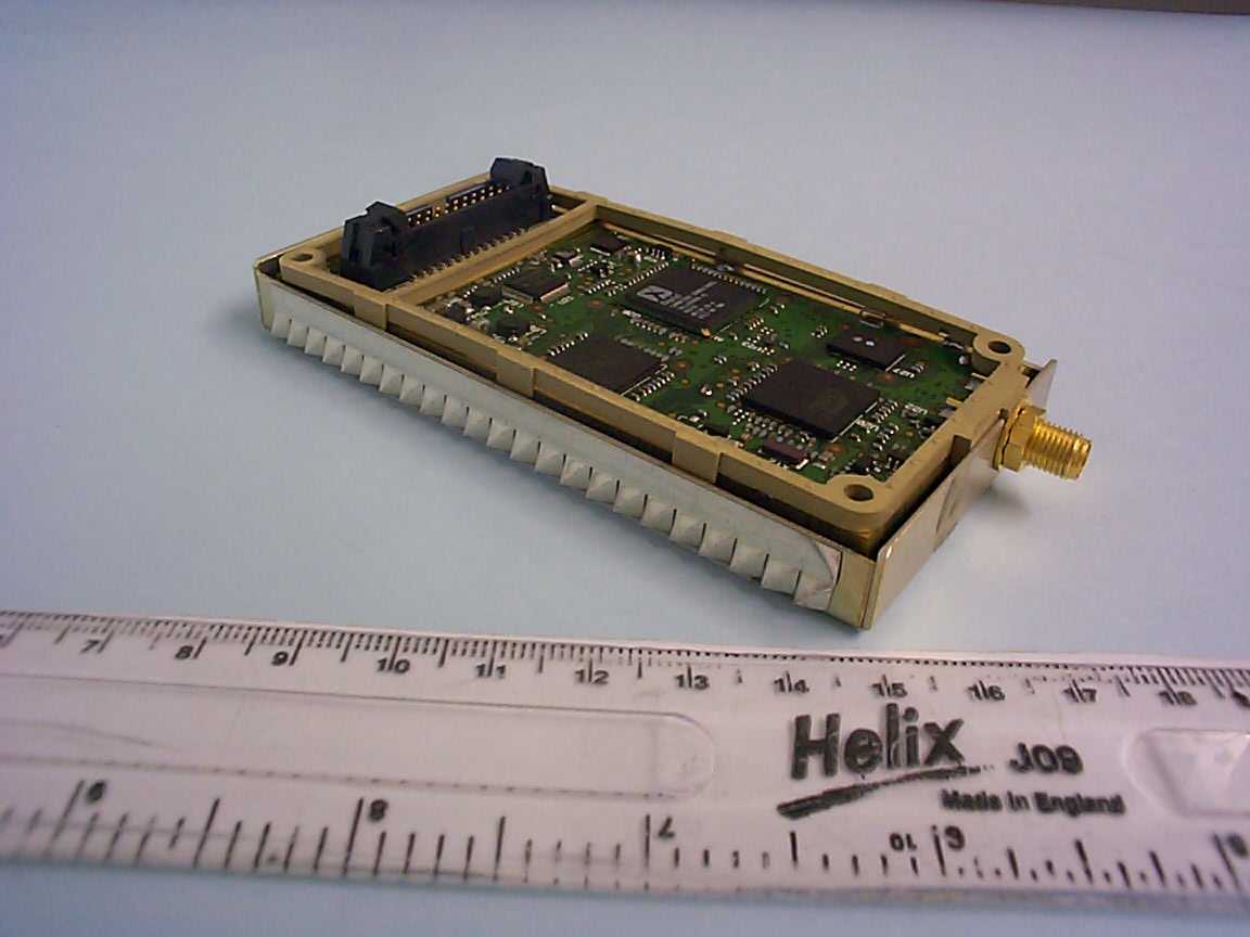
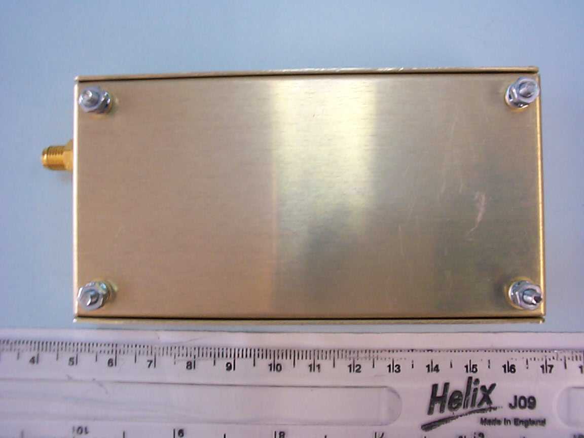
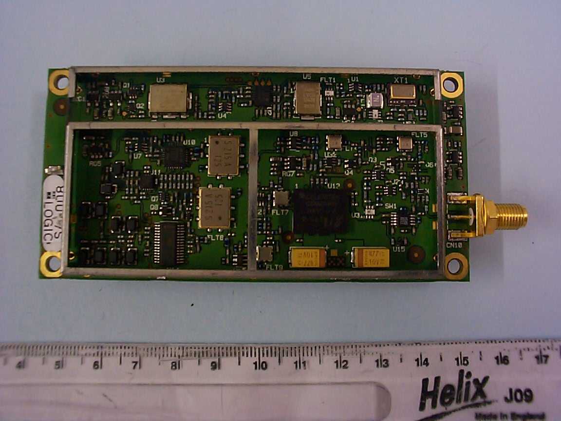
Q639601Satellite SBD Transceiver module type 9601
Iridium Satellite LLC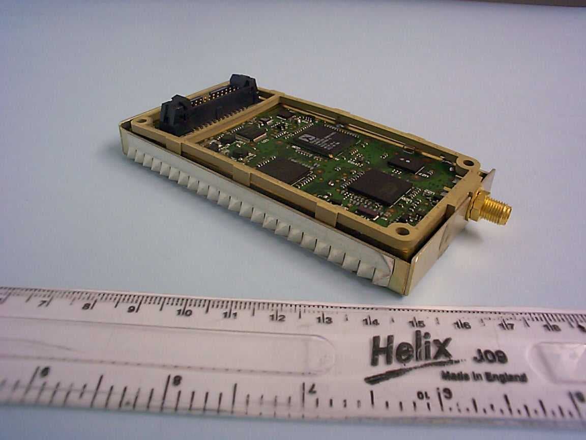
Click to zoom
Application Details
- Equipment Class
- TNB - Licensed Non-Broadcast Station Transmitter
- Date of Grant
- Nov 10, 2005
- Application Purpose
- Original Equipment
- Date of Application
- Nov 10, 2005
- Equipment Note
- Satellite SBD Transceiver module type 9601
- Frequency Range
- 1616.00000000 - 1626.50000000
- Company
- Iridium Satellite LLC
- Country
- United States
Documents & Files
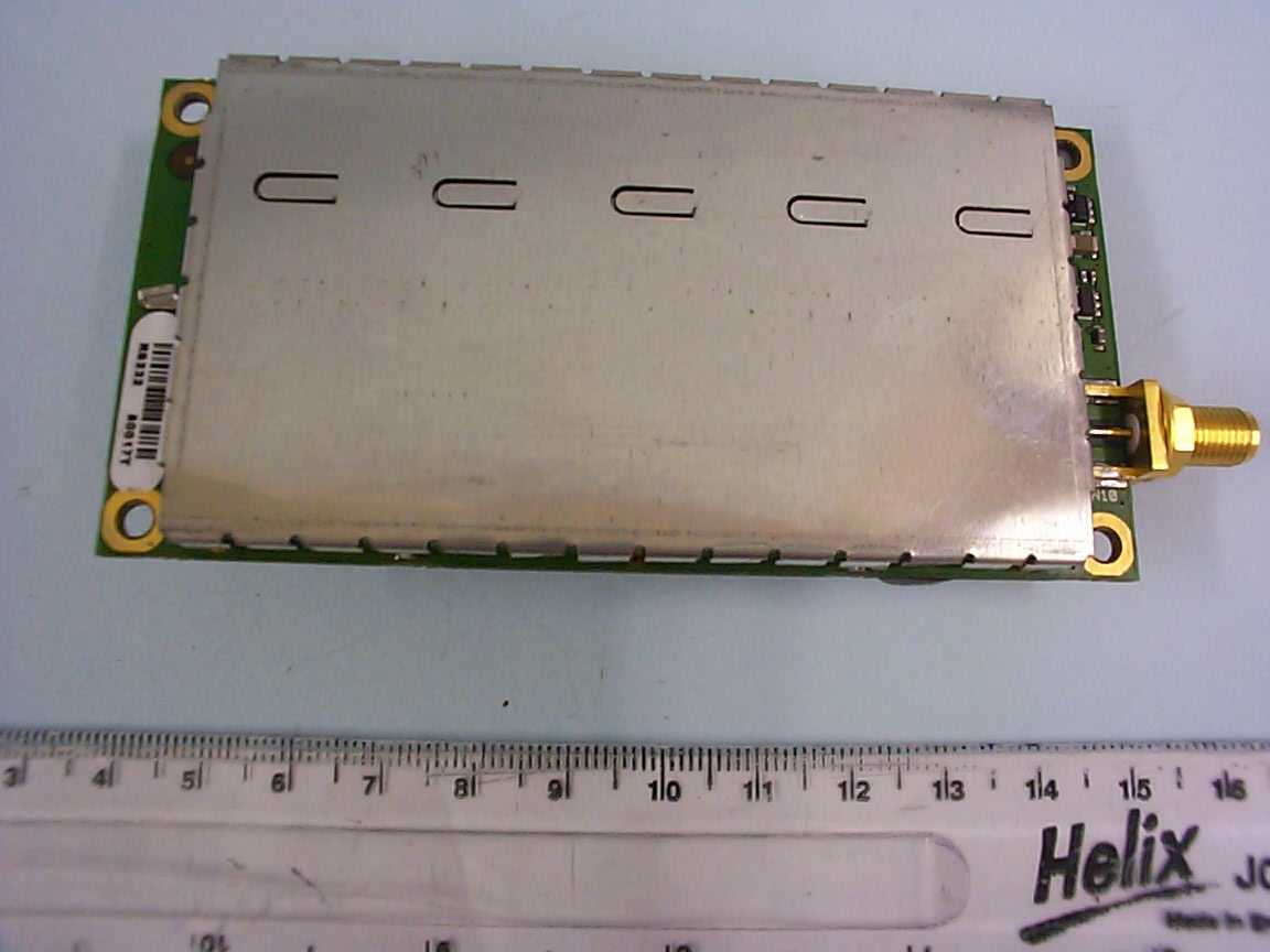
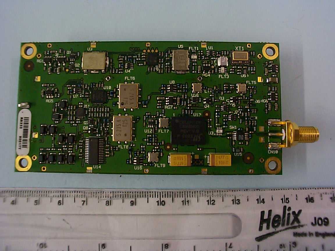
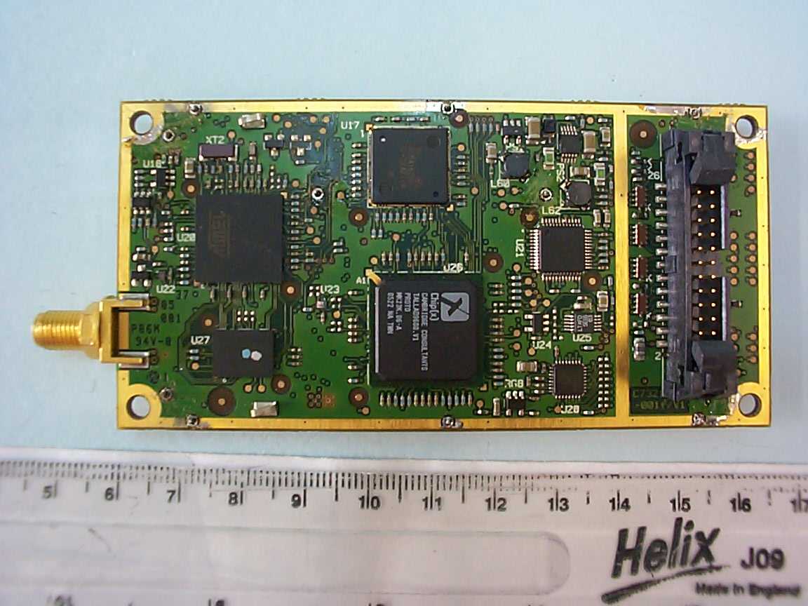
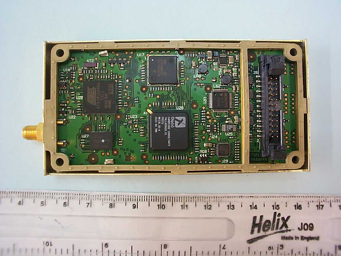
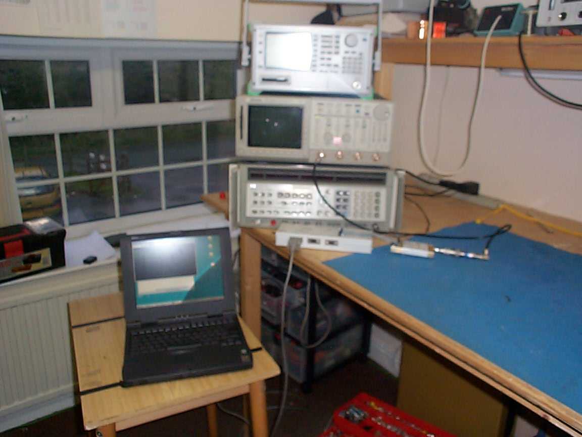
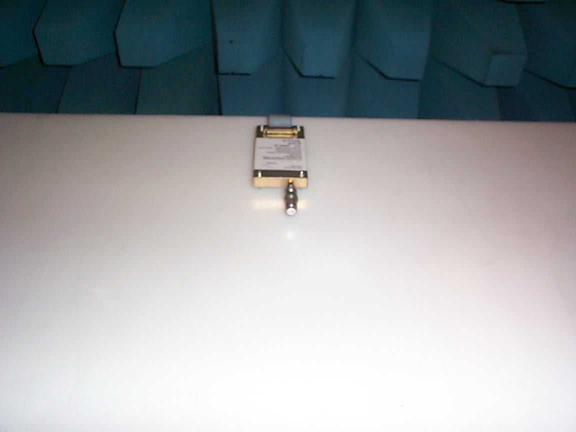
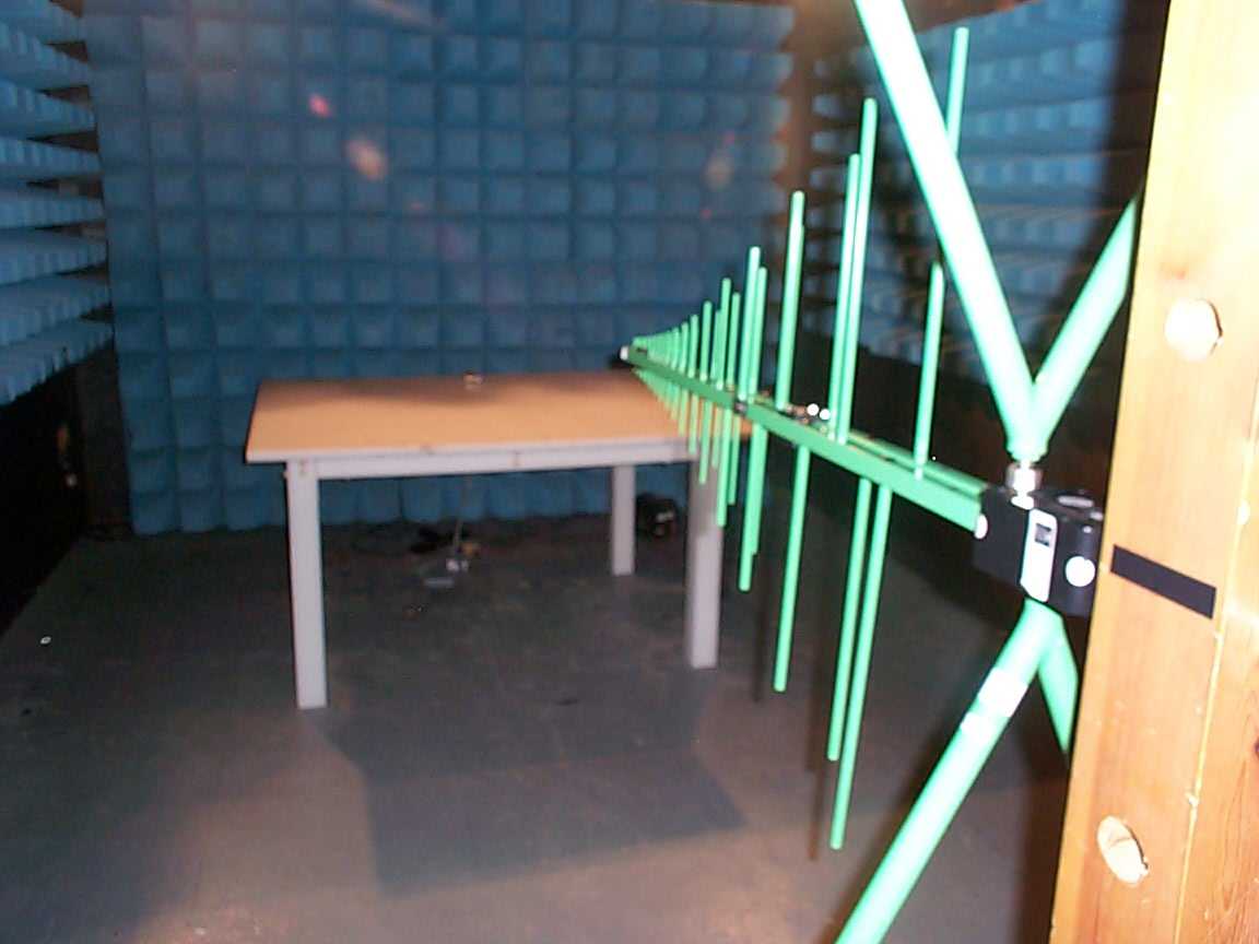
Document Text
Text extracted from the exhibit documents filed with the FCC. Open a document above to read the original.
Users Manual
9 6 0 1S h o r t B u r s t D a t a O n l yT r a n s c e i v e r P r e l i m i n a r yP r o d u c tD e v e l o p e r sG u i d e R e v i s i o n 1.2 A u g u s t 2 8 t h 2 0 0 5 I r i d i u m S a t e l l i t e L L C P r o p r i e t a r y & C o n f i d e n t i a l I n f o r m a t i o n Iridium Satellite LLC 6701 Democracy Blvd., Suite 500 Bethesda, MD 20817 USA www.iridium.com Toll Free: +1.866.947.4348 [US Only] International +1.480.752.5155 email:[email protected] IridiumSatellite LLC 9601SBDTransceiver PreliminaryProductDevelopersGuide V1.2082905 Iridium Satellite LLC Proprietary & Confidential Information Information contained herein is preliminary and subject tochange without further notice 2 Preliminary Product InformationPurpose &Disclaimer This document contains preliminaryproductinformationfor the newIridium9601Short Burst DataTransceiver.The purpose of providing this information is to enable Value Added Resellers and Value Added Manufacturers to begin to understand the product and how to integrate it into a complete wireless data solution. By providing the information contained herein, Iridium Satellite LLC makes no guarantee or warranty, and does not assume liability with respect to theaccuracy or the completeness of such information, orto the results of use of theplannedproduct in any specific instance, and hereby expressly disclaims any implied warranties of merchantability or fitness for a particular purpose, or any other warranties or representations whatsoever, expressed or implied. Iridium Satellite LLC reserves the right to modify orchange specifications,detailed herein,at any timewithout notice. Export Compliance Information This product is controlled by the export laws and regulations of the United States of America. The U.S. Government may restrict the export or re-export of this product to certain individuals and/or destinations. For further information, contact the U.S. Department of Commerce, Bureau of Industry and Security or visitwww.bis.doc.gov. Revision History RevisionDateComment V1.0May 022005First revision V1.2Aug 28 2005 Second revision incorporatingmajorupdates. Key updates are: Product name change to“9601 SBD Transceiver” Physicalpackaging Connector types updated AT Commands added and updated IridiumSatellite LLC 9601SBDTransceiver PreliminaryProductDevelopersGuide V1.2082905 Iridium Satellite LLC Proprietary & Confidential Information Information contained herein is preliminary and subject tochange without further notice 3 Contents Preliminary Product Information Purpose & Disclaimer...............................................................................2 Revision History............................................................................................................................................2 List of Abbreviations.....................................................................................................................................4 1.0Product Overview..................................................................................................................5 1.1Key Features.........................................................................................................................5 1.2Transceiver Packaging and Regulatory Certification............................................................6 2.0Physical Specifications..........................................................................................................7 2.1Dimensions............................................................................................................................7 2.2Mechanical Dimensions–Mounting......................................................................................9 2.2.1Mounting-Stackable Design...............................................................................................10 2.2.2Mounting to a Panel/Surface–For use with cable connections.........................................12 2.3Environmental......................................................................................................................14 2.4Interface Connectors...........................................................................................................14 3.0Electrical Interfaces.............................................................................................................15 3.1Multi-Interface Connector....................................................................................................15 3.1.1Connector Type...................................................................................................................15 3.1.2Connector Pin Allocation.....................................................................................................16 3.2DC Power Interface.............................................................................................................18 3.2.1Power On/Off Control..........................................................................................................18 3.3Serial Data Interface............................................................................................................19 3.3.19-Wire and 3-Wire Operation...............................................................................................19 3.3.2Configuration Settings.........................................................................................................20 3.3.3Modes of Operation.............................................................................................................21 3.4Hardware Failure Reporting................................................................................................21 3.5Network Available Output....................................................................................................21 3.6DC Power Output................................................................................................................21 4.0RF Interface...............…
Text truncated - open the document above for the full version.
Block Diagram
Commercially confidential Subject: Talladega Short Burst Data Module System SpecificationIridium and CCL Use Only C7321-S-002 v1.6Page 23 of 43 07 September 2005 Figure 3: Baseband and Digital Block Diagram Receiver ADC (12 bit differential) Fs = 2.4MHz Tx DAC (12 bit differential) Fs = 2.4MHz Serial link Parallel bus Radio System Interface TI DAC2932 LTC1403A Call Processor (ARM7) ASIC 8MByte FLASH 1MByte SRAM Address, control and 16 bit data Sync Serial Sync Serial Parallel Bus DACs IF converter glue logic and high rate processing Data / Fax Serial Interface Timing control USART 1 Real Time Clock ADCs Control ADCs (10 bit single-ended) DSP ('C54x) TI TMS320VC5416-160 Atmel AT91M55800A Control DACs (10 bit single-ended) HPI McBSPs SPI Synth and demod control (sync serial) Synthesizer control Demodulator control Auxilliary DACs: 4 channels, 12 bits Control DACs (12 bit single-ended) S71PL064 module Data / Fax Serial Interface DPL Serial Interface (for test) RST +2V9+2V5 +1V6 Reset Generator MAX6700 RTC Power VDDBU Debug UART 6.1 Call Processor The call processor (CP), an Atmel AT91M55800A, is the master system processor. It has control of the frame timing: the DSP and all other devices operate as slaves to the CP. The CP device includes not only the processor core, but also the following components in the same part: • 8k byte of static RAM, • a power management controller and clock generator block, • a real time clock (RTC), • a watchdog timer, • an interrupt controller, • three asynchronous serial ports, • a timer-counter block, • an SPI interface, • eight channels of ADC, and
Block Diagram
Commercially confidential Subject: Talladega Short Burst Data Module System SpecificationIridium and CCL Use Only C7321-S-002 v1.6Page 18 of 43 07 September 2005 5 RF Chain Design Figure 2: Receiver and Transmitter Block Diagram, Analogue Sections TX RF SAW 2 Hitachi HWEJ901 (FLT7) Temperature compensated attenuator RF Amplfier MGA-62563 (U12) RF Power detector LTC5509 (U9) Forward TX RF SAW 1 Hitachi HWEJ901 (FLT9) LO Notch filter TX Mixer CMY210 (U16) TX IF Filter TFS215A (FLT8) TX IF Amplifier BFP540F (Q9) +5V External DC Supply TX_LO Transmitter Receiver RX_LO 1401 - 1411 MHz , Rx Mixer CMY210 (U8) RX IF SAW Filter TFS215A (FLT6) From modulator DACs in Digital Section Rx RF SAW 2 Hitachi HWEJ901 (FLT4) TX IQ Modulator and VGA MAX2510 (U14) IQ 600kHz Reconstruction filters I Q TX_F_PDETECT 214.4MHz +5.0V Vcc Attenuator TX_PWR_CNTL TX_OK Directional Coupler and low-pass filter Rx 2nd IF Downconverter MAX2309 (U10) RX_IF_LO 428.8 MHz Real only, 600kHz differential signal to base-band ADC Tx IF LO Buffer MGA-62563 (U7) TX_IF_LO 3 Wire serial interface 600 kHz differential amplifier LT6203 (U11) RX_VGC RXM_STBYB RXM_SHDNB PA Module (U13) 215.0 MHz 1401 - 1411 MHz TX_PA_VDD_MON Attenuator -11 dB 800MHz Notch Filter Rx RF SAW 1 Hitachi HWEJ901 (FLT5) LNA2 BFP540F (Q3) TX_PREKEY + _ T/R SWITCH HMC546 (SW1) 0-f+f RC Polyphase Filter IP IN QP QN LNA1 BFP540F (Q6) 214.4MHz DC Celeritek CSM20403 RG7 +3V Regulator +3.0V Vcontrol TX_PA_CTL C? 940 uF 50 mOhm 2W, +33dBm Antenna Connector Output match & Harmonic filter Driver Stage MMIC Output Stage MMIC Interstage Match Reflected TX_R_PDETECT Attenuator -2 dB DC RF Power detector LTC5509 (U29) -20dB VSWR_TRIP VSWR trip LMV7239 (U32) 600kHz anti-alias filter 5.1 Frequency Plan The block diagram for the RF and IF analogue sections of the transmit and receive architecture is shown in Figure 2. 3 The receiver is a conventional dual conversion superhet with an RF input of 1616MHz to 1626.5MHz, a first IF of 215MHz and a low second IF of 600kHz. A real-only output is provided at the second IF frequency for analogue-to-digital conversion at a sample rate of 2.4 MHz. The image of the second mixing process is suppressed by means of a two-section polyphase filter. The ASIC performs a final frequency conversion to bring the signal to a quadrature pair at zero frequency. The transmit frequency plan is identical although the architecture is different. The DSP processor generates a pair of baseband quadrature components at a sample rate of 200 kHz. In digital hardware these are translated to an IF of 600 kHz at a sample rate of 2.4 MHz. The two quadrature components are converted to analogue signals in the DACs, filtered to remove alias components and translated in a single-side band mixer to an IF of 215 MHz. After filtering the signal is then mixed to the output frequency of 1616 to 1626.5 MHz. 3 The first spin on the Talladega PCB will use the H1b 8W PA, all subsequent spins will use the new lower power 2W PA.
ID Label/Location Info
1 : 1 mm Artwork for 9601 SBD Transceiver Label 1 1 0.1N/AN/A C7321-AW-002 NAMD 24-Aug-2005 3M 7816 Thermal Transfer Label Mtl. 2.0 mil (51 micron) Gloss Radiant White Polyester, 0.8 mil (20 micron) #310 Acrylic Adhesive, 3.2 mil (81 micron) 55# Densified kraft liner. (TBC) Printed as shown (TBC) 100 mm 100 mm 100 mm 100 mm THIRD ANGLE PROJECTION TITLE SHEET OF CCL DRAWING No. MATERIAL FINISH SCALEDIM’S IN DRAWN BY DATE CHECKED STANDARD TOLERANCES WHOLE NUMBERS (eg 35) ±0.5mm SINGLE DECIMAL (eg 35.3) ±0.2mm DOUBLE DECIMAL (eg 35.30) ±0.1mm WHOLE NUMBER ANGLE (eg 90°) ±1° SINGLE DECIMAL ANGLE (eg 90.0°) ±0.5° CCL FreeHand Drawing Format v2.2 A3 © Cambridge Consultants Limited, 2002 Address: Science Park, Milton Road, Cambridge, CB4 0DW, England Telephone: +44 (0)1223 420024 ISSUE CHANGE NOTE No. APPROVED / DATE SUPPLIER’S REFCLIENT’S REF COMMERCIALLY CONFIDENTIAL. This Drawing contains ideas and information which are proprietary to Cambridge Consultants Limited: it is given to you in confidence. You are authorised to open and view any electronic copy we send you of this document within your organisation and to print a single copy. Otherwise the material may not in whole or in part be copied, stored electronically or communicated to third parties without the prior written agreement of Cambridge Consultants Limited. 0.2N/AN/A 0.3N/AN/A 0.4N/AN/A 1.0N/AN/A 2.0MC3 14-Sep-2005C7321-CN-022 3.0MC3 06-Oct-2005C7321-CN-025 NOTES 1. Printed PANTONE Colour(s) : Process Black 2. IRIDIUM Signature Logo scaled to size = 15.0 mm wide 3. NON-VARYING PRINT : To be based on .eps file of same File Name and Issue No. 4. Position Label as shown - application to be free from creases and bubbles 52.00 (max flat area) 134.70 62.00 6.75 R 2.00 (4 POS’N) 16.3552.00 (max flat area)7.60 46.00 (printed area)9.7522.3546.00 (printed area)10.60 29.0 15.0 SBD Transceiver Model 9601 RoHS Compliant IC: 4629A 9601 FCCID: Q639601 Made in Malaysia CAUTION : No User Serviceable Parts. Warranty voided if opened. Read instructions on use & disposal. To Contact Iridium Satellite: +1.480.752.5155 N12037 Pb fix IMEI label here SBD Transceiver Model 9601 RoHS Compliant IC: 4629A 9601 FCCID: Q639601 Made in Malaysia CAUTION : No User Serviceable Parts. Warranty voided if opened. Read instructions on use & disposal. To Contact Iridium Satellite: +1.480.752.5155 N12037 Pb SBD Transceiver Model 9601 RoHS Compliant IC: 4629A 9601 FCCID: Q639601 Made in Malaysia CAUTION : No User Serviceable Parts. Warranty voided if opened. Read instructions on use & disposal. To Contact Iridium Satellite: +1.480.752.5155 N12037 Pb
Operational Description
Cambridge Consultants Ltd Science Park Milton Road Cambridge England CB4 0DW Tel +44 (0)1223 420024 Fax +44 (0)1223 423373 [email protected] www.CambridgeConsultants.com Commercially confidential You are authorised to open and view any electronic copy we send you of this document within your organisation and to print a single copy. Otherwise the material may not in whole or in part be copied, stored electronically or communicated to third parties without the prior written agreement of Cambridge Consultants Limited. C7321-S-002 v1.6 07 September 2005 Talladega Short Burst Data Module System Specification Monaco Family Products Iridium Satellite LLC 6701 Democracy Boulevard Suite 500 Bethesda MD 20817 U.S.A. Prepared by Richard Davies Reviewed by Marion Campbell Accepted by Mark Adams Commercially confidential Subject: Talladega Short Burst Data Module System SpecificationIridium and CCL Use Only C7321-S-002 v1.6Page 2 of 43 07 September 2005 Revision History (This table will be filled in from V1.0 onwards, V1.0 being the first complete version of this document.) VersionDateAuthorComment V1.04 April, 2005Richard DaviesFirst complete version (including RS232) for review by Iridium. V1.118 th April 2005 Marion CampbellUpdated after review by Iridium, see IRF-004 V1.1 for review comments. V1.26 May 2005Richard DaviesAdded Appendix B and Appendix C. V1.330 June 2005Richard DaviesUpdated to reflect changes in connectors. Voltage levels corrected in Appendix A. V1.419 July 2005Richard DaviesChanged RTC supply maximum. Updated approach to EMC and ESD protection to reflect P3 design goals. V1.512 August 2005 Richard DaviesChanged RTC current draw, added DPL data rate in 3.2.8, updated ESD protection, no test connector for P3, added Inmarsat rejection figure at 10 MHz V1.67 September 2005 Richard DaviesRemoved external power source for real-time clock for P3 build 2 onwards Distribution Iridium Satellite LLCMark Adams Conrad Geibel Hon Lam Cambridge ConsultantsProject Reviewer – Richard Traherne Project Manager – Marion Campbell Project Team Commercially confidential Subject: Talladega Short Burst Data Module System SpecificationIridium and CCL Use Only C7321-S-002 v1.6Page 3 of 43 07 September 2005 Table of Contents List of References5 Glossary5 1Introduction7 1.1Scope7 1.2Numbering of prototype versions7 2System Overview8 3Interfaces10 3.1Antenna10 3.2User Connector10 3.2.1Power Input10 3.2.1.1Power Supply Requirements11 3.2.2Power On/Off Control11 3.2.3RTC Power11 3.2.4Data Port11 3.2.590ms Synchronization Input (Ext 11Hz)12 3.2.6Network Available12 3.2.7Supply Output13 3.2.8Digital Peripheral Link (DPL)13 3.2.9ESD protection and EMC filtering13 3.2.10User Connector Pin Allocation13 3.3Test Connector (P1 and P2 only)15 3.3.1Software Development Support15 3.3.2Test Connector Pin Allocation16 4Functional Partitioning17 5RF Chain Design18 5.1Frequency Plan18 5.2Rejection of Interference from Inmarsat Terminals19 5.3Transmit Path19 5.3.1Baseband to IF19 5.3.2RF Section19 5.3.3PA19 5.3.4RF Power Control20 5.3.5Tx Burst Control21 5.4Receive Path21 5.4.1Tx / Rx Switch21 5.4.2LNA21 5.4.3Mixer21 5.4.4IF Filter21 5.4.5IF Gain, AGC, Second Conversion and Second IF21 5.5Synthesisers22 6Baseband and Digital Design22 6.1Call Processor23 6.2DSP24 Commercially confidential Subject: Talladega Short Burst Data Module System SpecificationIridium and CCL Use Only C7321-S-002 v1.6Page 4 of 43 07 September 2005 6.3ASIC24 6.4IF Converters and Radio Interface26 7DSP Software Design26 7.1Overview26 7.1.1Executive27 7.1.2Modem27 7.1.3Common Routines28 7.2Operating System28 8Call Processor Software Design29 8.1Overview29 8.1.1L-Band Physical29 8.1.2Layer 230 8.1.3Layer 330 8.1.4Hardware Drivers30 8.1.5NVS30 8.1.6ATC30 8.1.7Data Task31 8.1.8Application Task31 8.1.9DPL31 8.2DSP Interface31 8.3Baseband Timing31 8.3.1CP Timers31 8.3.2ASIC Timers32 8.4RF Control32 8.5Real Time Clock Driver32 8.6UART driver32 8.7Reflected Power Trip33 8.8Operating System33 8.9Built in Test33 9Power Supply Design34 9.1PA Supply34 9.2Other supplies34 9.3Current Consumption35 10 Physical Requirements35 10.1Size35 10.2Cost35 10.3Screening35 11 Antenna Requirements36 12 Appendix A, internal analogue/digital interfaces37 12.1Analogue IF37 12.1.1Analogue control and sense signals37 12.1.2Digital control bus38 12.1.3Discrete digital control and status39 12.2Power supplies for RF circuits40 13 Appendix B, 25-way D connector pin-out41 Commercially confidential Subject: Talladega Short Burst Data Module System SpecificationIridium and CCL Use Only C7321-S-002 v1.6Page 5 of 43 07 September 2005 14 Appendix C, protection requirements for filter board43 List of References RefTitleDocument Number 1Monaco H1b Transceiver Board circuit diagram C7032-CD-012 version e 2Talladega System Block DiagramC7321-SCH-001 3Talladega RF System Level DesignC7321-TM-001 4DPL Protocol and Hardware Specification C7032-S-018 5Short Burst Messaging Air Interface Specification, version 0.8 C7321-RD-006 6Iridium Short Burst Data Service Developers Guide C7321-RD-004 7Talladega AT Command ReferenceC7321-S-005 8Talladega Test Interface Card (TIC) Specification C7321-S-006 9Custom Digital IC Design SpecificationC7321-S-001 Glossary Abbrev.Full Name ADCAnalogue to Digital Converter AGCAutomatic Gain Control ASICApplication Specific Integrated Circuit CPCall Processor CPLDComplex Programmable Logic Device CWCarrier Wave (unmodulated) DACDigital to Analogue Converter DCDirect Current DPLDigital Peripheral Link DSPDigital Signal Processor EEPROMElectrically Erasable Programmable Read Only Memory ESREquivalent Series Resistance FPGAField Programmable Gate Array Commercially confidential Subject: Talladega Short Burst Data Module System SpecificationIridium and CCL Use Only C7321-S-002 v1.6Page 6 of 43 07 September 2005 Abbrev.Full Name IFIntermediate Frequency IMEIIridium Mobile Equipment Identifier INSIridium Network Simulator I/OInput/Output IQIn-phase and Quadrature JTAGJoin…
Text truncated - open the document above for the full version.
Test Report
TRL COMPLIANCE SERVICES LTD EMC DIVISION L ONG GREEN FORTHAMPTON GLOUCESTER GL19 4QH UNITED KINGDOM T ELEPHONE +44 (0)1684 833818 FAX +44 (0)1684 833858 E- MAIL [email protected] www.trlcompliance.com FS 21805 TEST REPORT NO: RU1196/6596 COPY NO: 2 ISSUE NO: 1 FCC ID: Q639601 REPORT ON THE CERTIFICATION TESTING OF AN IRIDIUM SATELLITE LLC SBD TRANSCEIVER WITH RESPECT TO THE FCC RULES CFR 47, PART 25 TEST DATE: 4 th October 2005 – 14 th October 2005 TESTED BY: D WINSTANLEY APPROVED BY: P GREEN PRODUCT MANAGER EMC DATE: 3 rd November 2005 Distribution: Copy Nos: 1. Cambridge Consultants Limited 2. TCB: TRL Compliance Services Limited 3. TRL EMC THIS DOCUMENT MAY BE REPRODUCED ONLY IN ITS ENTIRETY AND WITHOUT CHANGE RU1196/6596 Page 2 of 54 CONTENTS PAGE CERTIFICATE OF CONFORMITY & COMPLIANCE 3 APPLICANT’S SUMMARY 4 EQUIPMENT TEST CONDITIONS 5 TESTS REQUIRED 5 TEST RESULTS – Transmitter RF Output Power - Conducted 7 Emissions Limitations - Conducted 8 Spurious Emissions - Conducted 9 Spurious Emissions - Radiated 10 Frequency Stability -Temperature 11 Frequency Stability -Voltage 12 ANNEX PHOTOGRAPHS A APPLICANT’S SUBMISSION OF DOCUMENTATION LIST B TEST EQUIPMENT C TEST SETUP SELECTION D DUTY CYCLE E EMISSIONS LIMITATIONS F TRANSMITTER SPURIOUS EMISSIONS – Conducted G TRANSMITTER SPURIOUS EMISSIONS – Radiated H FREQUENCY STABILITY – Temperature I FREQUENCY STABILITY – Voltage J Notes: 1. Component failure during test YES NO [ ] [X] 2. If Yes, details of failure: 3. The facilities used for the testing of the product contain in this report are FCC Listed. RU1196/6596 Page 3 of 54 CERTIFICATE OF CONFORMITY & COMPLIANCE FCC IDENTITY: Q639601 PURPOSE OF TEST: Certification TEST SPECIFICATION: FCC Rules CFR 47, Part 25 TEST RESULT: Compliant to Specification ITU EMISSIONS DESIGNATOR 41K7V7W EQUIPMENT UNDER TEST: SBD Transceivers MODEL TESTED 9601 EQUIPMENT TYPE: Satellite Communications Module MAXIMUM OUTPUT 9601 Model = 1.6dBW ANTENNA TYPE: External SMA connector. For test purposes applicant declared a Fixed Mast Antenna with a gain of 3dBi CHANNEL SPACING: 41.667 kHz NUMBER OF CHANNELS: 252 MODULATION TYPE: V7W POWER SOURCE(s): +5 Vdc TEST DATE(s): 4 th October 2005 – 14 th October 2005 ORDER No(s): 025675/MC3 APPLICANT: Iridium Satellite LLC ADDRESS: 6701 Democracy Blvd. Suite 500 Bethesda United States of America MD 20817 TESTED BY: D WINSTANLEY APPROVED BY: P GREEN PRODUCT MANAGER EMC RU1196/6596 Page 4 of 54 APPLICANT’S SUMMARY EQUIPMENT UNDER TEST (EUT): SBD Transceiver EQUIPMENT TYPE: Satellite Communications Module PURPOSE OF TEST: Certification TEST SPECIFICATION(s): FCC Rules CFR 47, Part 25 TEST RESULT: COMPLIANT Yes No [X] [ ] APPLICANT’S CATEGORY: MANUFACTURER IMPORTER DISTRIBUTOR TEST HOUSE AGENT [X] [ ] [ ] [ ] [ ] APPLICANT’S CONTACT PERSON(s): Mr C Geibel E-mail address: [email protected] APPLICANT: Iridium Satellite LLC ADDRESS: 6701 Democracy Blvd. Suite 500 Bethesda United States of America MD 20817 TEL: +1 301 571 6277 FAX: +1 301 571 6250 MANUFACTURER: Iridium Satellite LLC DEVELOPMENT AGENT Cambridge Consultants Limited DEVELOPMENT AGENT S CONTACT PERSON(s): Ms M Campbell E-mail address: [email protected] ADDRESS: Science Park Milton Road Cambridge CB4 4DW United Kingdom TEL: +44 (0)1223 420024 FAX: +44 (0)1223 423373 EUT(s) COUNTRY OF ORIGIN: United States TEST LABORATORY: TRL EMC UKAS ACCREDITATION No: 0728 TEST DATE(s) 4 th October 2005 – 14 th October 2005 TEST REPORT No: RU1196/6596 RU1196/6596 Page 5 of 54 EQUIPMENT TEST / EXAMINATIONS REQUIRED 1. TEST/EXAMINATION FCC Part 2 FCC Part 25 APPLICABILITY RESULT RF Power Output - 25.204 (a) YES PASS Emissions Limitations - 25.202 (f) YES PASS Spurious Emissions at Antenna Terminals 2.1051 25.202 (f) 25.213 YES PASS Protection of the Radio Navigation Satellite Service - 25.216(c) 25.216(f) YES PASS Spurious Emissions Radiated 2.1053 25.202 (f) 25.213 YES PASS Frequency Stability Temperature 2.1055 25.202 (d) YES PASS Frequency Stability Voltage 2.1055 25.202 (d) YES PASS Note: The SBD Transceiver is subject to FCC Part 25 & Part 2 for FCC Certification for units marketed within the United States. The above tests, as specified in FCC Part 2, with limits as defined in FCC Part 25 were performed on the SBD Transceiver. 2. Product Use: Satellite Data Communications 3. Emission Designator: 41k7V7W 4. Temperatures: Ambient (Tnom) 20 o C 5. Supply Voltages: Vnom +5 Vdc Note: Vnom voltages are as stated above unless otherwise shown on the test report page Single channel [ ] Two channel [ ] 6. Equipment Category: Multi-channel [X] 7. Channel spacing: Narrowband [X] 41.667 kHz Wideband [ ] 8. Test Location TRL Compliance Services Up Holland [X] Long Green [ ] 9. Modifications made during test program No modifications were performed. RU1196/6596 Page 6 of 54 Product Description The satellite communications module consists of an L-Band Transceiver (LBT) capable of simultaneous transmit and receive (duplex) operation covering the frequency range of 1616MHz to 1626.5MHz. The frequency accesses used for duplex channels are organised into sub-bands each of which contains eight frequency accesses. Each sub-band, therefore occupies 333.33 kHz (i.e. 8x41.667kHz). Up to 30 sub-bands containing 240 frequency accesses may be used for duplex channels. Standard References 47 CFR 2 Code of Federal Regulations, Title 47, Part 2, “Frequency allocations and Radio Telemetry Matters; 10-1-03 Edition General Rules and Regulations” 47 CFR 25 Code of Federal Regulations, Title 47, Part 25,”Sattelite Communications” Subpart C, 10-1-03 Edition “Technical Matters” C63.4-2003 American National Standards Institute (ANSI), “Methods of Measurement of Radio Noise Emissions from Low Voltage Electrical and Electronic Equipment in the Range 9 kHz to 40 GHz” RU1196/6596 Page 7 of 54 COMPLIANCE TESTS TRANSMITTER TESTS RF OUTPUT POWER – CONDUCTED – PART 25.204 (a) Ambient temperature = 22 o C Radio Laboratory Relative humidity = 66% …
Text truncated - open the document above for the full version.
Contact Information
Applicant
Kathy Morgan(Chief Legal Officer)
Technical Contact
Cambridge Consultants LtdRichard Davies
[email protected]+44 1223 392423
Science Park · Cambridge · United Kingdom
Test Firm
TRL Compliance LtdJohn Charters
Technical Specifications
| # | Rule Parts | Frequency Range | Power Output | Emission | Tolerance |
|---|---|---|---|---|---|
| 1 | 25 | 1.62 GHz - 1.63 GHz | 2 W | 41K7V7D | 1.0000000000 ppm |
Other Applications from Iridium Satellite LLC
Q639604
Apr 09, 2026Hybrid LTE-M Cellular + IRIDIUM Satellite + GNSS module for IoT
Equipment Class
TNB - Licensed Non-Broadcast Station TransmitterQ639704
Dec 08, 2024Data satellite transceiver module for use with the Iridium satellite communications network.
Equipment Class
TNB - Licensed Non-Broadcast Station TransmitterQ639690
Aug 18, 2020Standalone satellite device with Java application programming environment. Includes internal power supply, Iridium Short Burst Data Transceiver, GNSS, BLE, I/O, RS232, RS485, CAN.
Equipment Class
TNB - Licensed Non-Broadcast Station Transmitter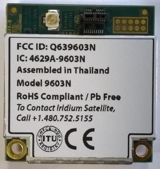
Q639603N
Aug 26, 2014Short Burst Data Transceiver
Equipment Class
JBP - Part 15 Class B Computing Device Peripheral
Q639560
Mar 31, 2014Iridium 9560 Wi-Fi Access Point with satellite transceiver
Equipment Class
DTS - Digital Transmission System