Q6N035RF27MHz Radio Transmitter
EDU Science Co., Ltd.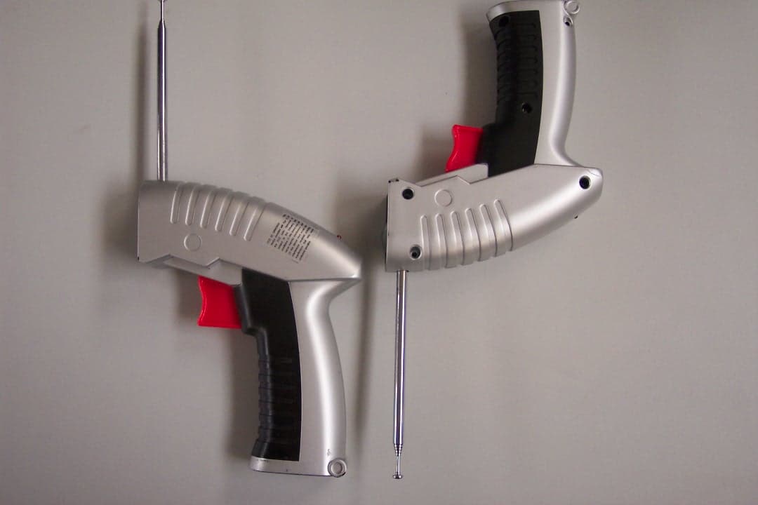
Click to zoom
Application Details
- Equipment Class
- DXX - Part 15 Low Power Communication Device Transmitter
- Date of Grant
- May 06, 2004
- Application Purpose
- Original Equipment
- Date of Application
- May 06, 2004
- Equipment Note
- 27MHz Radio Transmitter
- Frequency Range
- 26.98500000 - 27.22500000
- Company
- EDU Science Co., Ltd.
- Country
- Hong Kong
Documents & Files
Document Text
Text extracted from the exhibit documents filed with the FCC. Open a document above to read the original.
Users Manual
1 3 6 7 8 10 U.S. AND INTERNATIONAL P ATENTS PENDING Contains NiMH battery, battery must be recycled or disposed of properly. Battery Care - For maximum perfor mance, always allow your battery of the Vectron Ultralite to drain before recharging. - Never charge a second time without discharging first. This will affect or damage the battery. - Do not dispose of the battery in your regular household waste. - Contact your local waste management officials for infor mation on environmentally sound disposal of rechargeable batteries. - If a battery leak develops, a void contact with leaking fluid. Place the damaged battery in a plastic bag for proper disposal. - If fluid comes in to contact with skin or eyes , wash with cool water for at least 15 mins. Battery Disposal - Your Vectron Ultralite is only to be charged under adult supervision. - Never expose the Vectron Ultralite battery pack to direct sun, hot areas, or fire as it may explode. - The Ultralite charger and battery may become war m during charging. - The Ultralite charging cord must be disconnected from the Vectron Ultralite when it is fully charged. - Never leave your Vectron Ultralite connected to the AC adaptor over night. - Never overcharge the Vectron Ultralite as it can damage the rechargeable battery. Battery Safety 5 2 I) Thrust Transmitter 2) Insert 1 9V (6LR61) Alkaline battery. Trigger Antenna Power On Indicator 1) Open or close the cover with a Philips screwdriv er . CLOSE OPEN 4 Contents Auto-stop Safety Propeller AC Adaptor Thrust Transmitter Launch Platform Rechargeable Battery Infrared Receiver Red LED Green LED Power Switch (ON / OFF) Ring Charging Socket II) Flight Preparation 1) Place your Vectron Ultralite on to the launch platfor m. WARNING: Never recharge your Vectron Ultralite a second time without having flown first. Continuous recharging without discharging first, will damage the Ultralite battery. CAUTION: Always recharge your Vectron Ultralite with supplied AC Adaptor! Operate with third-party AC Adaptor may cause damage to this product. 2) NOTE: After the red and green LED blink alternately, the red LED will start to flash slowl y. At this time your Vectron Ultralite is ready for take off. III) Flying, Hovering and Landing Your Vectron Ultralite 1) 2) Switch on your Vectron Ultralite. IMPORTANT: Ensure your Vectron Ultralite is fully charged for first time use and that you have a least 10 ft. (3 m) of clear area. Learning More About Your Vectron Ultralite Vectron Ultralite Flying Range (max.) 12 meters Tec hnical Specifications 1 x 9V (6LR61) Alkaline Battery Ultralite Controller Battery P ower Consumption 0.3 W (Peak) 10 and UP Recommended Age Wor king Voltage (DC) 7~9 V Wor king Voltage 5 V Wor king Current 1.5 W (Peak) 3) Extend the antenna of the thrust tr ansmitter. 4) Press the trigger slowly to allow your Vectron Ultralite to take off. TIPS: - For your first flight, ensure there are no strong air currents from fans, air conditioners or open windows. - Adjust the trigger to find the correct position so your Vectron Ultralite will hover preventing it from flying too high or too low. It will take some practice to get the hang of it. - Always point the thrust transmitter towards your Vectron Ultralite to ensure a steady controllable flight. - Do not try to land your Vectron Ultralite on to the launch platform. Try to land on any open floor area. - Your Vectron Ultralite can also take off from any smooth flat surface. Do not try to take off from deep pile carpet or soft furniture. This may jam the propeller before take off. 5) Adjust and hold the trigger to allow your Vectron Ultralite to hover . 6) Release the trigger to allow your Vectron Ultralite to descend or land. co ver The next generation of flying toys has arrived. The World's Smallest Wireless Flying Saucer! Excitement in the air! ON OFF NOTES: - The red and green LED will blink alternately. It will take approximately 10 minutes to charge your Vectron Ultralite completely; at this point the green LED will flash continuously. - When your Vectron Ultralite is new or has not been flown for a long time it will take several charge/discharge cyc les for the battery to reach its full flight time. Rechargeable Battery Type 6 V 100mA Ni-MH Ultralite Charging Devices I) AC Adaptor Output DC 13V 5.4W AC Adaptor Input 120V AC 60Hz 10W Charge Duration 10 minutes (max.) - V detect plus master timeout Charge Method R Your Vectron Ultralite does not respond to the thrust transmitter. The thrust transmitter battery is low. The red LED does not flash after depressing the trigger. Replace the 9V (6LR61) Alkaline battery with new one. The thrust transmitter battery is inserted improperly . Check and reinsert the battery with the proper polarity as per the markings in the holder. Your Vectron Ultralite is out of range. Move closer to your Vectron Ultralite. NOTE: The transparent labels underneath the ring are for protection against the propeller. A damaged ring can be repaired with transparent tape. Some glues may damage the polyf oam ring. You are outdoors or flying in a large room with high ceiling. Fly indoors with the appropriate ceiling height. 9 Troubleshooting Your AC Adaptor is the wrong type or damaged preventing it from charging your Vectron Ultralite. Contact your support team at [email protected] stating the voltage and plug type required. Do not return your Vectron Ultralite to the retail store. The propeller auto-stop feature is activated. This feature is activated when the propeller is obstructed by body parts or objects. If your Vectron Ultralite crashes on to the floor, this may trigger the auto-stop feature as well. The red and green LED will blink alternately. Reset your Vectron Ultralite by switching it off and turning it back on again to resume flight. Pr oblem P ossible Cause Solution Your Ultralite battery is not charged. Charge your battery fully before flying. The battery power is low. Recharge the battery fully. Your Vectron Ultral…
Text truncated - open the document above for the full version.
Operational Description
EL035RF Ultralite, 27MHz Transmitter Operation Description ©Copyright 2004 EDU-SCIENCE (HK) LIMITED May 26, 2003 Confidential Page 1 of 1 Microprocessor (Encoder) Single Chip Integrated Circuit FSK Transmitter PLL (Phased Lock Loop) 4MHz Crystal RF Ampilifier ThrottleSignal 27MHz carrier with modulated signal TXO Frequency (channel width 30KHz) 1. 26.985 MHz, used 2. 27.015 MHz, used 3. 27.045 MHz, used 4. 27.075 MHz, used 5. 27.105 MHz, used 6. 27.135 MHz, used 7. 27.165 MHz, used 8. 27.195 MHz, used 9. 27.225 MHz, used The Radio Frequency of the transmitter is based a low cost single-chip Integrated Circuit (U1) to establish a 27MHz frequency-agile RF link. It can generate 27MHz FSK carrier frequency via its internal Phased-Lock Loop frequency divider and external components crystal (Y1, shared with Microprocessor), Resistor (R2), capacitors (C1, C2). The carrier frequency (TXO Frequency) can be selectable from 26.985 MHz to 27.225MHz with typical channel spacing of 30KHz via input pins of 13, 14, 15 and 16 (U1). EL035RF Ultralite, 27MHz Transmitter Operation Description ©Copyright 2004 EDU-SCIENCE (HK) LIMITED May 26, 2003 Confidential Page 2 of 2 The Microprocessor (U2) reads input signal from variable resistor (VR1) and modulates the output signal via I/O pin 15 (U2, DATA) to the RF transmitter IC (U1). The RF Transmitter (U1) synthesizes 27MHz FSK carrier frequency via its output pin 10 (TXO) to the final stage of RF amplifier, which amplifies (Q1) the signal into the antenna (C31, C30, C20, C19, C18, C16, R15, L3 and L15)
Test Report
Report No.: 04.04.0826EF Page: 1 of 10 FCC ID: Q6N035RF Authorized Signature: Kent Hsu Laboratory Manager SGS-CSTC Co., Ltd. This report refers to the General Conditions for Inspection and Testing Services, printed overleaf This report details the results of the testing carried out on one sample. The results contained in this test report do not relate to other samples of the same product and does not permit the use of the SGS PRODUCT CERTIFICATION MARK.. The manufacturer should ensure that all products in series production are in conformity with the product sample detailed in this report. This report may only be reproduced and distributed in full. If the product in this report is used in any configuration other than that detailed in the report, the manufacturer must ensure the new system complies with all relevant standards. Any mention of SGS International Electrical Approvals or testing done by SGS International Electrical Approvals in connection with, distribution or use of the product described in this report must be approved by SGS International Electrical Approvals in writing. Member of the SGS Group (Société Générale de Surveillance) SGS-CSTC Standards Technical Services Ltd. 1/F., Building No. 1 Building, Agriculture Machinery Materials Co. Wushan Road, Shipai, Tianhe District,Guangzhou, China Telephone: +86 (0) 20 3848 1001 Fax: +86 (0) 20 3848 1006 [email protected] FEDERAL COMMUNICATIONS COMMISSION Registration number: 282399 FCC TEST REPORT Application No. : 04.04.0826E Applicant: Edu-Science (HK) Ltd. FCC ID: Q6N035RF Fundamental Carrier Frequency : 26.985 MHz, 27.015 MHz, 27.045 MHz, 27.075 MHz, 27.105 MHz, 27.135 MHz, 27.165 MHz, 27.195 MHz, 27.225 MHz ♣ ♣ Please refer to section 3.2 of this report which indicates which Fundamental Carrier Frequency was actually tested and which models are electrically identical. Equipment Under Test (EUT): Name: Wireless Ultralite Model: EL035RF Standards: FCC PART 15, SUBPART C : 2002 Date of Receipt: 16 & 24 April 2004 Date of Test: 22 to 30 April 2004 Date of Issue: 30 April 2004 Test Result : PASS * * In the configuration tested, the EUT complied with the standards specified above. FCC ID No.: Q6N035RF SGS-CSTC Standards Technical Services Ltd. 2 Contents Page 1 COVER PAGE.........................................................................................................................................................1 2 CONTENTS .............................................................................................................................................................. 2 3 GENERAL INFORMATION.................................................................................................................................. 3 3.1 CLIENT INFORMATION....................................................................................................................................... 3 3.2 DETAILS OF E.U.T. ............................................................................................................................................ 3 3.3 DESCRIPTION OF SUPPORT UNITS....................................................................................................................... 3 3.4 TEST LOCATION................................................................................................................................................. 3 3.5 OTHER INFORMATION REQUESTED BY THE CUSTOMER...................................................................................... 3 3.6 TEST FACILITY................................................................................................................................................... 4 4 TEST RESULTS....................................................................................................................................................... 5 4.1 TEST INSTRUMENTS........................................................................................................................................... 5 4.2 E.U.T. OPERATION............................................................................................................................................ 5 4.3 TEST PROCEDURE & MEASUREMENT DATA....................................................................................................... 5 4.3.1 Radiated Emissions ...................................................................................................................................... 5 4.3.2 Occupied Bandwidth .................................................................................................................................... 7 4.3.3 Photographs - Radiated Emission Test Setup in Chamber ..........................................................................8 5 PHOTOGRAPHS - EUT CONSTRUCTIONAL DETAILS ...........................................................................9-10 FCC ID No.: Q6N035RF SGS-CSTC Standards Technical Services Ltd. 3 General Information 3.1 Client Information Applicant Name: Edu-science (HK) Ltd. Applicant Address: Suite 701, 7/F, Wing on plaza, 62 Mody Road, TST East, Kln., Hong Kong 3.2 Details of E.U.T. Product Name: Wireless Ultralite Model: EL035RF Fundamental Carrier Frequency : 26.985 MHz, 27.015 MHz, 27.045 MHz, 27.075 MHz, 27.105 MHz, 27.135 MHz, 27.165 MHz, 27.195 MHz, 27.225 MHz ♣ Only test one product which fundamental carrier frequency is 26.985MHz. Since all the products were electrically identical only the fundamental carrier frequencies were different. Power Supply: 9V DC (1 x 'ALKALINE ( 6LR61)' Size Battery) Power Cord: N/A- 3.3 Description of Support Units The EUT was tested as an independent unit: a 27MHz radio transmitter. 3.4 Test Location All tests were performed at:- SGS-CSTC Standards Technical Services Ltd., Guangzhou Safety & EMC Laboratory, 1/F, Building No. 1, Agriculture Machinery Materials Company Warehouse Ltd., Wushan Road Shipai, Tianhe District, Guangzhou, China. P.C. 510630. Tel: +86 20 …
Text truncated - open the document above for the full version.
Contact Information
Applicant
Bardeen Lai(Executive Director)
Test Firm
SGS-CSTC Standards Technical StandardsKent Hsu
Technical Specifications
| # | Rule Parts | Frequency Range | Power Output |
|---|---|---|---|
| 1 | 15C | 26.985 MHz - 27.225 MHz | - |
Other Applications from EDU Science Co., Ltd.
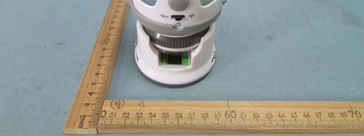
Q6NMS079
Feb 09, 2015Wireless IP WiFi Digital Microscope
Equipment Class
DTS - Digital Transmission System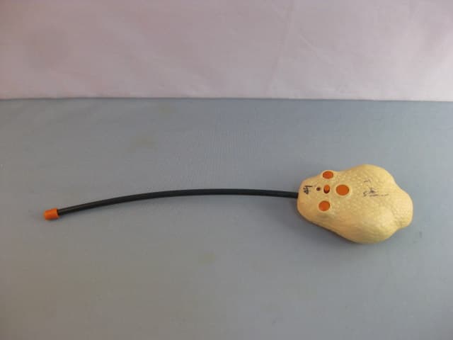
Q6N322ELB
Sep 16, 2010RADIO CONTROLLED RATTLE SNAKE
Equipment Class
DXX - Part 15 Low Power Communication Device Transmitter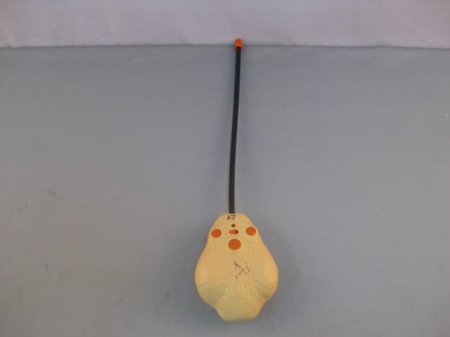
Q6N322ELA
Jul 05, 2010RADIO CONTROLLED RATTLE SNAKE
Equipment Class
DXX - Part 15 Low Power Communication Device Transmitter
Q6N199ELB
Jun 07, 2007RC Pterosaur (Transmitter)
Equipment Class
DXX - Part 15 Low Power Communication Device Transmitter
Q6N199ELA
Jun 07, 2007RC Pterosaur (Transmitter)
Equipment Class
DXX - Part 15 Low Power Communication Device Transmitter