Q6N149ELRC CRAWLERS ( SCORPION/TARANTULA)
EDU Science Co., Ltd.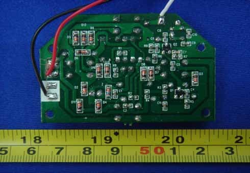
Click to zoom
Application Details
- Equipment Class
- DXX - Part 15 Low Power Communication Device Transmitter
- Date of Grant
- Apr 27, 2006
- Application Purpose
- Original Equipment
- Date of Application
- Apr 27, 2006
- Equipment Note
- RC CRAWLERS ( SCORPION/TARANTULA)
- Frequency Range
- 27.14500000 - 27.14500000
- Company
- EDU Science Co., Ltd.
- Country
- Hong Kong
Documents & Files
Document Text
Text extracted from the exhibit documents filed with the FCC. Open a document above to read the original.
Users Manual
RC TARANTULA P38-EL150-81001000 - To prevent battery leakage: Be sure to insert batteries correctly. - Batteries should be replaced by adult. - Never dispose of batteries in fire as this may cause them to explode. - Do not mix old and new batteries (replace all batteries at the same time). - Do not mix alkaline, standard (carbon-zinc) or rechargeable (nickel-cadmium) batteries (or equivalent). Only batteries of the same or equivalent type as recommended are to be used. - Non-rechargeable batteries are not to be recharged. - Always remove exhausted or dead batteries from product. Remove batteries from product that is not going to be used for a long time. Otherwise, the batteries may leak and cause damage. - The supply terminals are not to be short-circuited. - Make sure battery compartment is secure. - Do not immerse battery operated toys. Wipe clean only. Battery Safety Guidelines 2) Insert one 9V (6LR61) battery. 1) Open or close the cover with a Philips screwdriver. Remote Controller: Battery Installation Bring your RC Tarantula's movements to life by setting him in motion. Press these button(s), your RC Tarantula will move: Forward Backward Left Right Turn the base unit switch to "ON". Assembly ON OFF 23 The device complies with Part 15 of the FCC rules. Operation is subject to the following conditions: (1) this device may not cause interference, and (2) this device must accept any interference received, including interference that may cause undesired operation. FCC ID: Q6N149EL 1) Open or close the cover with a Philips screwdriver. Tarantula: 2) Insert 4 size "AA" (LR6) 1.5 V batteries.
Block Diagram
Encoder 27/49MHz Oscillator RF Ampilifier Control Commands Signal 27/49MHz carrier with modulated signal Transmitter Block Diagram Decoder Signal Amplification 27/49MHz Oscillator Motor Control Signal Signal 27/49MHz Examined signal Receiver Block Diagram Dual Motor Control Unit
External Photos
EUT –Front View EUT – Back View
ID Label/Location Info
FCC ID Label This device complies with Part 15 of the FCC Rules. Operation is subject to the following two conditions:(1)this device may not cause harmful interference,and (2) this device must accept any interference received, including interference that may cause undesired operation. The Label must not be a stick-on paper. The Label on these products must be permanently affixed to the product and readily visible at the time of purchase and must last the expected lifetime of the equipment not be readily detachable. Proposed Label Location on EUT EUT Bottom View/proposed FCC Mark Location Operation is subject to the following two conditions: 1. This device may not hfl
ID Label/Location Info
FCC ID Label Sample for Model:EL149/150 FCC ID:Q6N149EL This device complies with Part 15 of the FCC Rules. Operation is subject to the following two conditions: (1) This device may not cause harmful interference, and (2) This device must accept any interference received, including interference that may cause undesired operation.
Internal Photos
PCB – Component View PCB – Solder View
Operational Description
RC Crawlers, 27/49MHz Transmitter Operation Description ©Copyright 2006 EDU-SCIENCE (HK) LIMITED 27 Jun, 2005 Confidential Page 1 of 3 Encoder 27/49MHz Oscillator RF Ampilifier Control CommandsSignal 27/49MHz carrier with modulated signal The Radio Frequency of the transmitter is based on standard 27/49MHz AM (Amplitude Modulation) citizen’s band. It generates low power 27/49MHz AM carrier frequency via major components of CRY, R3, R6, L1, Q1, C4, C5, C12and C11 (Figure 1). Figure 1 RC Crawlers, 27/49MHz Transmitter Operation Description ©Copyright 2006 EDU-SCIENCE (HK) LIMITED 27 Jun, 2005 Confidential Page 2 of 3 The Encoder (U1, Figure 2) reads input commands and modulates these commands (intelligent) with the carrier frequency (as shown in figure 1) via pin 8 (SO, U1, Figure 2) to the RF amplifier. Figure 2 RC Crawlers, 27/49MHz Transmitter Operation Description ©Copyright 2006 EDU-SCIENCE (HK) LIMITED 27 Jun, 2005 Confidential Page 3 of 3 The modulated signal is passed to the final stage of RF amplifier (Figure 3), which amplifies (Q2, R7, C6, C7) the signal and then couples the signal into the antenna (ANT1) via components C8, C9, C10,L2, L3 and L4. Figure 3
Test Report
FCC TEST REPORT FCC ID : Q6N149EL Applicant : EDU-SCIENCEHKLIMITED Address : Suite 701-703 Wing On Plaza TST East,Kowloon Hong Kong Equipment Under Test (EUT) : Product description :RC Crawlers(Scorption/Tarantula) Model No. : EL149/EL150 Standards : FCC 15 Paragraph 15.205, Paragraph 15.209, Paragraph 15.227, Paragraph 15.31, Paragraph 15.33, Paragraph 15.35. Date of Test : Mar.22, 2006 Test Engineer : Tiger Su Reviewed By : PERPARED BY: Waltek Services (Shenzhen) Co., Ltd. 8C,West Tower, Aidi Building, No.5003 Binhe Rd, Futian District, Shenzhen518045, Guangdong, China. Tel: 86-755-83551033 Fax: 86-755-83552400 Page 1 of 21 EDU-SCIENCE(HK) LIMITED Q6N149EL 2 Contents Page 1 COVER PAGE..........................................................................................................................................................1 2 CONTENTS..............................................................................................................................................................2 3 TEST SUMMARY....................................................................................................................................................4 4 GENERAL INFORMATION..................................................................................................................................5 4.1 CLIENT INFORMATION............................................................................................................................................5 4.2 GENERAL DESCRIPTION OF E.U.T...........................................................................................................................5 4.3 DETAILS OF E.U.T..................................................................................................................................................5 4.4 DESCRIPTION OF SUPPORT UNITS...........................................................................................................................5 4.5 STANDARDS APPLICABLE FOR TESTING..................................................................................................................5 4.6 TEST FACILITY........................................................................................................................................................6 4.7 TEST LOCATION......................................................................................................................................................6 5 EQUIPMENT USED DURING TEST...................................................................................................................7 6 CONDUCTED EMISSION TEST..........................................................................................................................8 6.1 TEST EQUIPMENT....................................................................................................................................................8 6.2 TEST PROCEDURE...................................................................................................................................................8 6.3 CONDUCTED TEST SETUP.......................................................................................................................................9 6.4 EUT OPERATING CONDITION.................................................................................................................................9 6.5 CONDUCTED EMISSION LIMITS.............................................................................................................................10 6.6 CONDUCTED EMISSION TEST RESULT...................................................................................................................10 7 RADIATION EMISSION TEST...........................................................................................................................11 7.1 TEST EQUIPMENT..................................................................................................................................................11 7.2 MEASUREMENT UNCERTAINTY.............................................................................................................................11 7.3 TEST PROCEDURE.................................................................................................................................................11 7.4 RADIATED TEST SETUP.........................................................................................................................................12 7.5 SPECTRUM ANALYZER SETUP...............................................................................................................................12 7.6 CORRECTED AMPLITUDE & MARGIN CALCULATION............................................................................................13 7.7 SUMMARY OF TEST RESULTS................................................................................................................................13 7.8 EUT OPERATING CONDITION...............................................................................................................................14 7.9 RADIATED EMISSIONS LIMIT.................................................................................................................................14 7.10 RADIATED EMISSIONS TEST RESULT................................................................................................................15 8 OCCUPIED BANDWIDTH..................................................................................................................................17 8.1 TEST PROCEDURE.................................................................................................................................................17 9 PHOTOGRAPHS OF TESTING SET UP...........................................................................................................18 9.1 RADIATION EMISSION TEST VIEW....................................................…
Text truncated - open the document above for the full version.
Test Setup Photos
Photographs - Test Setup Radiated Emissions
Contact Information
Applicant
Bardeen Lai(Executive Director)
Test Firm
Shenzhen Academy of Metrology & Quality InspectionPeter Lin
Technical Specifications
| # | Rule Parts | Frequency Range | Power Output |
|---|---|---|---|
| 1 | 15C | 27.145 MHz - 27.145 MHz | - |
Other Applications from EDU Science Co., Ltd.
Q6NMS079
Feb 09, 2015Wireless IP WiFi Digital Microscope
Equipment Class
DTS - Digital Transmission System
Q6N322ELB
Sep 16, 2010RADIO CONTROLLED RATTLE SNAKE
Equipment Class
DXX - Part 15 Low Power Communication Device Transmitter
Q6N322ELA
Jul 05, 2010RADIO CONTROLLED RATTLE SNAKE
Equipment Class
DXX - Part 15 Low Power Communication Device Transmitter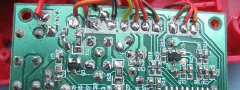
Q6N199ELB
Jun 07, 2007RC Pterosaur (Transmitter)
Equipment Class
DXX - Part 15 Low Power Communication Device Transmitter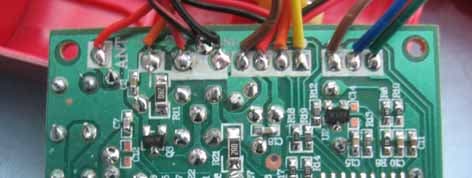
Q6N199ELA
Jun 07, 2007RC Pterosaur (Transmitter)
Equipment Class
DXX - Part 15 Low Power Communication Device Transmitter